Abstract
At present, software products for numerical simulation of fluid dynamics problems (ANSYS Fluent, Ansys CFX, Star CCM, Comsol, etc.) problems are widely used. These software products are mainly based on the numerical solution of the Navier–Stokes equations, the most common and computationally easy method of solving, which is Reynolds averaging (RANS), and further closing the system using semi-empirical turbulence models. Currently, there are many modeling methods and turbulence models; however, there are no generalized recommendations for setting up grid models for modeling flows, while for practical use both the correct mathematical models and the setting of the computational grid are important. In particular, there are no generalized recommendations on the choice of scale of global elements of grid models for typical single channels. This work is devoted to the development and study of relations for a priori estimation of the parameters of a grid model in relation to solving hydrodynamic problems with fluid flow in channels. The paper proposes the introduction of a generalized grid convergence criterion for single channels at high Reynolds numbers. As single channels, a channel with a sudden expansion, a channel with a sudden contraction, and diffuser channels with different opening angles are considered. Based on the results of variant calculations of typical single channels at various Reynolds numbers and various geometric parameters, generalized criterion correlations were obtained to find dimensionless linear scales of grid elements relative to the hydrodynamic characteristics of the flow in the channel. Variant calculations of the compound channel were investigated, which showed the adequacy of correlations proposed.
1. Introduction
At present, the modeling of fluid dynamics processes in the flow in channels is an urgent task associated with the development and design of complex science-intensive products in power engineering, aviation and other industries. The main difficulty in modeling hydro-gas-dynamic processes lies in the correct modeling of the turbulence phenomenon, which is characterized by:
- Non-stationarity;
- Irregularity, lack of strict order in time;
- Randomness;
- Three-dimensionality;
- Viscous and vortex nature of the flow;
- Coherence of large vortex structures.
Usually, the flow regime becomes turbulent at Reynolds number (Re) more than a critical values, which is different for various types of flow. The Re by definition is:
where:
- —characteristic size, m.
- —characteristic velocity, m/s;
- —viscosity, m2/s. There are currently several main approaches to modeling turbulence:
- Direct numerical simulation (DNS) [1] calculates the Navier–Stokes equations for eddies of all scales up to the Kolmogorov scale. With an increase in the size of the computational cell, the system of equations for DNS, as a rule, does not converge. At present, the DNS is used mainly for research purposes and in modeling low-Re currents.
- Large eddy modeling (LES) [2] uses the separation of eddies by scale: large eddies are directly resolved, small eddies are modeled using subgrid models. LES methods require a grid of the order of the scale of large eddies. Currently, LES is used in scientific research and technical applications as a highly accurate method.
- Modeling of Reynolds-averaged Navier-Stokes equations or unsteady Reynolds-averaged Navier-Stokes equations (RANS, URANS) [3]. Modeling is done by closing the equations through Boussinesq hypothesis and semi-empirical turbulence models over the entire energy spectrum.
At present, this method is most widely used in technology in the development of new equipment, scientific research, etc. Figure 1 shows a comparative diagram of DNS, LES and RANS/URANS approaches for modeling turbulent flows. The hybrid methods as a detached eddy simulation (DES) [4] are between LES and RANS/URANS in terms of physicality and volume of calculations.

Figure 1.
Comparison of different approaches to modeling turbulent flows.
There are a large number of turbulence models for the RANS method, the most widely used of which are the two-parameter models of the k-ε [5] and k-ω [6] groups. The main difference between the turbulence models of the k-ε group is the type of differential equations that allow, together with the averaged system of Navier–Stokes equations, to determine the kinetic energy of turbulence and the rate of its dissipation. Additional differential equations for k and ε are transport equations of the given quantities. The k-ω and Shear Stress Transport (SST) turbulence models are traditionally referred to as the low Reynolds group of turbulence models. The turbulence model k-ω is similar to the turbulence models from the high-Reynolds k-ε family, only in this case, to determine the turbulent viscosity, differential equations are additionally solved for the specific dissipation rate of kinetic energy ω. One of the most versatile turbulence models is the k-ω SST hybrid model. The group of equations of the low Reynolds SST [7] turbulence model includes equations for the high Reynolds k-ε turbulence model solved for the flow core and equations for the low Reynolds k-ω turbulence model solved for the boundary layer region.
Since RANS methods, unlike LES and DNS methods, do not directly calculate vortex structures, but model them using semi-empirical models, there are no unambiguous criteria for constructing grid models [3] related to the scales of resolvable vortex structures that can be built for these methods for DNS and LES methods [8]. At the same time, the formation of recommendations for the construction of computational grids that ensure high calculation accuracy for specific geometric and regime characteristics is an important applied task, since it allows for advanced verification of flow modeling, which in turn reduces the number of numerical and physical experiments.
The paper [9] summarizes recommendations for numerical modeling of flow processes in the interblade channels of turbines. Based on the results of the review, the authors recommend the use of the k-ω SST model, the use of inflation in the vicinity of the wall with the thickness of the first near-wall element corresponding to y+ < 1, as well as recommendations for choosing the size of the global mesh element, corresponding to the number of elements in the range between 500,000 and 1,500,000. The y+ is the dimensionless universal flow coordinate, which is by definition:
where:
- y—wall distance, m.
- —shear velocity, m/s.
- —viscosity, m2/s.
Using the example of modeling thermal–hydraulic processes occurring in the core of the CANDU (Canada Deuterium Uranium) reactor, it was shown in [10] that a good approximation at a Reynolds number of 2.3 · 106 is provided with a number of elements of the grid model of 84 million, while the size of the element in the zones of a high-velocity gradient should not exceed 0.4 mm. It is also noted in the work that during modeling, a much greater sensitivity is manifested to a change in the size of the global element than to a change in the size of the near-wall cells.
The main problem of using the data of the above works is the lack of generalized recommendations for constructing grid models for the sizes of global elements, while for near-grid cells there are recommendations for choosing sizes (y+ < 5 for low Reynolds models and y+ > 30 for high Reynolds ones) [11].
For a global element of a grid model, an important characteristic is the grid convergence point [12] when conducting a grid-independence study. The grid convergence point is the value of the element size, at which a further decrease in the element size does not lead to a noticeable increase in the accuracy of calculations; therefore, this value is of great importance, since it is the optimal element size that provides the required modeling accuracy at relatively low computational costs.
The paper [13] presents the results of the study of grid convergence as applied to modeling the external flow around a wind turbine with a Darrieus rotor. The paper proposes a methodology and correlations for estimating element sizes in relation to URANS modeling using the SST model, using a combination of the Courant number (Co) and the newly introduced GRV (Grid-Reduced Vorticity) criterion. The advantages of the described approach include a high degree of physical validity, as well as high accuracy. The disadvantages are the need to construct the vorticity field, which excludes the possibility of a priori estimation of the size of the grid model.
The purpose of this work is to form correlations for estimating the sizes of global elements of grid models that provide grid convergence in modeling fluid dynamics processes in turbulent flow in typical single channels, which are considered channels with sudden expansion, sudden contraction, as well as diffuser channels. In this case, the ratios must be designed for application for use in a wide range of operating characteristics and meet the following requirements:
- The size of the grid element in correlations should be associated with characteristic hydrodynamic quantities that have a length scale and characterize the flow regime.
- The nature of the quantities used should allow one to estimate the scale of the element a priori, before conducting numerical studies.
- Correlations should take into account the results of empirical and analytical studies of turbulent flows in channels.
The main novelty of this paper is the formulation of new grid convergence criteria, which has a physical sense and is related to the characteristic flow length scale. In the previous study [11] were estimated some recommendations for turbine blade channel modelling, but there are no generalized criteria, which can help to expand recommendations for more cases. On the contrary, in this study, a step is being taken towards the formulation of generalized criteria, which can be expanded on another geometry in the same class of cases in further studies. The formulation of generalized recommendations on the optimal mesh settings will allow the future to form a methodology for advanced verification of numerical simulation results.
2. Research Object
The objects of study in this paper are channels with a sudden expansion, with a sudden contraction, as well as diffuser channels. These types of channels are typical in relation to the problems of power engineering, in particular, channels with a sudden expansion and diffuser channels are characteristic geometries for combustion chambers of gas turbine plants, and channels with a sudden contraction are often found in shut-off and control valves, which, in particular, include faucets and valves.
To build a methodology for advanced verification, it is necessary to simulate the processes of fluid dynamics in single circular channels in a wide range of geometric and regime characteristics. Figure 2 shows the sketches of the single circular channels considered in this work; Table 1 shows their geometric and operating characteristics.
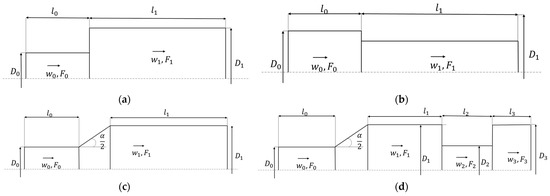
Figure 2.
Sketches of the considered geometries: (a)—channel with a sudden expansion; (b)—channel with a sudden contraction; (c)—diffuser channel; (d)—compound channel.

Table 1.
Geometrical and operating characteristics of the studied channels.
Characteristic Re for interblade channels of gas turbines ~104–105 [14,15,16] are considered as modes.
For the cases F0, l0, D0 are the cross-sectional area, length and diameter, respectively, of the channel until the diameter changes and F1, l1, D1 are these ones after changing. The is the diffuser opening angle and Re0 is the inlet Reynolds number.
In this paper, the compound channel is considered a control geometry for checking the correlations obtained during the study. The compound channel includes a diffuser section, a sudden contraction and a sudden expansion. The geometric and operating characteristics of the compound channel are shown in Table 2. For compound channel l0, D0 is the length and diameter, respectively, of channel until diffuser expansion and, l1, D1 are the ones after the diffuser region. The α is the diffuser opening angle and Re0 is the inlet Reynolds number. The D2, l2 and the D3, l3 is the diameter and length of the region after sudden contraction and after sudden expansion, respectively.

Table 2.
Geometrical and regime characteristics of the compound channel.
3. Research Method
Studying the problem for grid convergence is an important step in solving any problem; however, in the case of complex problems, the need to calculate several configurations leads to a significant increase in the overall computational complexity of the problem. In the case of forward verification, if the value of the optimal size of the global element is known, there is no need to conduct a large grid convergence study from the biggest scales of the grid element.
In the numerical simulation of hydrodynamic problems, the main source of simulation error is the low resolution of the grid model in areas with high velocity and pressure gradients. As applied to the flow in channels, the main velocity gradient is contained in the near-wall boundary layer, while in the core of the flow, the mean velocity practically does not change. The biggest local pressure gradients are contained near vortex generation sites as sharp corners or sudden flow direction change.
Figure 3 shows the velocity profile for a turbulent fluid flow in a channel in natural coordinates. This profile, when translated into dimensionless quantities in logarithmic coordinates, corresponds to the standard logarithmic turbulent profile.
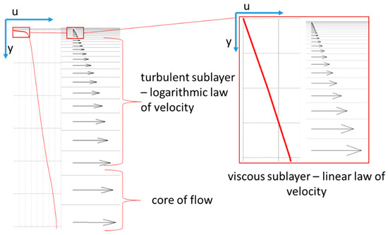
Figure 3.
Velocity profile for fluid flow in a channel in natural scale.
Figure 3 shows that the largest velocity gradient during fluid flow is concentrated in the viscous sublayer, for which there are current recommendations for choosing the heights of prismatic layers [17]. In a turbulent logarithmic boundary layer, the change in velocity is slower, but the gradient is also significant.
If we talk about the section of the logarithmic turbulent sublayer, then, as a rule, this section corresponds to the area of global grid elements, for which there are currently no practical generalized a priori recommendations for choosing linear dimensions. It is also important to note that a change in the size of the global element also affects the density of the grid in the direction of the fluid flow, which in turn affects the correctness of the calculation of the pressure field, which changes during a steady flow, mainly along the length of the channel.
Taking into account the structure of the flow, it is assumed that in order to ensure the required accuracy, the optimal sizes of global elements should be related by correlation dependences with characteristic scales characterizing the scale of turbulence in the flow. The optimal scale, in this case, would be the characteristic size of the vortex structures, but it cannot be estimated a priori, and therefore it is not suitable as a scale for constructing a priori correlation dependences.
On the other hand, using the relations for the logarithmic Prandtl velocity profile, one can construct correlations in which the thickness of the turbulent logarithmic sublayer, approximately corresponding to the dimensionless coordinate y+ = 200, is taken as the characteristic linear dimension. Taking into account the expression for near-wall layer height [16], it is possible to convert dimensionless coordinates into dimensional ones.
It is assumed that for all considered regimes within the framework of one considered turbulence model, the correlation:
where Ko—dimensionless value of the optimal value of the length of the control element, related to near-wall layer height, which is estimated by equations, presented in [18]:
where:
- —channel characteristic size, m;
- —optimal linear size of the global element of the grid model, m;
- —dimensionless distance from the wall corresponding to the transition to the flow core, [19];
- —the Reynolds number in the characteristic cross section of the channel, ; where is the characteristic flow velocity.
The Ko is the new criteria number of grid quality related to the characteristic length scale in the flow, proposed in this study. The physical meaning of Ko is the grid length scale divided by a near-wall layer height, which is estimated by . With increasing of Ko the grid quality will decrease because there will be less control volumes per wall layer, and on the contrary with decreasing of Ko grid quality will increase.
In this paper, the optimal size of a grid model element is considered to be the size that ensures grid convergence. This decision is due to the fact that in this size the numerical solution is quite accurate and further decrease in grid element size does not significantly effect. Wherein the decrease in cell size leads to an increased number of element, which require larger computing resources. As the characteristic size of the channel to determine Re’ and Ko in the case of channels with a varying cross-section, the size of the channel in the region of the greatest pressure losses is taken. For example, in the case of a canal with a sudden expansion, this is the diameter of the long wide part, in the case of a canal with a sudden contraction this is the diameter of tight part, for the diffuser this is the mean diameter between wide part and the tight part. The characteristic velocity to determine Re’ is the velocity, which matched the characteristic diameter of the channel.
The physical meaning of the hypothesis lies in the dependence of the element value and the height of the turbulent boundary layer on the flow regime in order to provide the necessary discreteness in the velocity gradient zone, which is the turbulent boundary layer.
The general research methodology includes:
- Conducting research on grid convergence for single channels with various regime and geometric characteristics.
- Revealing transition points to grid convergence using approximation power expressions.
- Reducing the values of the size of the element corresponding to the transition to the grid convergence to the dimensionless form Ko by dividing by the thickness of the turbulent boundary layer.
- Formation of correlations Ko(Re’) for individual channels with a test of statistical significance.
- Formation of the overall correlation Ko(Re’) with a test of statistical significance.
- Verification of the obtained general correlation dependence on the compound channel.
Modeling is planned to be carried out in an axisymmetric 2D RANS formulation, which provides fast calculation, which is valuable for practical engineering calculations, k-ω SST Menters Model [7] is used as a turbulence model. This model was chosen because of one of the best predictions for a flow with separation. Equations for the SST turbulence model for an incompressible fluid:
where:
—turbulent kinetic energy;
—turbulent kinetic energy specific dissipation rate;
—fluid density;
—fluid dynamic viscosity;
—fluid eddy viscosity;
—distance to the wall;
—time;
—coordinates by space;
, —blending functions;
—strain rate;
—fluid velocity;
—cross-diffusion term.
In this paper, there are no discussions about closing empirical coefficients, which are standard for the k-ω SST model in ANSYS Fluent 19.2:
The Ansys Fluent 19.2 software package was used for numerical simulation. The mesh and solver settings used in the simulation are shown in Table 3. An example mesh is shown in Figure 4. The boundary condition on the inlet is the velocity which is vary depending on Re and in the outlet is the Gauge pressure, which is equal to zero. To provide better accuracy there are prismatic pipe regions: 10D0 before the inlet and 10D1 after the outlet.

Table 3.
Mesh and solver settings.
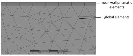
Figure 4.
An example of a computational grid near a wall.
As a control parameter characterizing the accuracy of the simulation, the coefficient of hydraulic resistance was used, calculated by the formula [20]:
where:
—coefficient of hydraulic resistance, obtained by numerical simulation;
—mass-averaged total inlet pressure, Pa;
—mass-averaged total outlet pressure, Pa.
The modeling error was estimated by the formula:
where:
—the value of the coefficient of hydraulic losses according to the literature data.
where:
—coefficient of hydraulic losses of pipes;
—coefficient of local losses, determined from the data [20];
—pipe’s diameter, m;
Coefficient of hydraulic losses of pipes calculated by the formula:
—pipe section length, m.
To test the hypothesis of the presence of a correlation, the Pearson test [21] is used. The condition for the presence of a correlation:
where:
—Pearson’s test statistics;
—critical value of the Pearson criterion;
The Pearson test statistic is determined by the formula [21]:
where:
—Pearson’s linear correlation coefficient.
The critical value of the statistics of the Pearson test is determined by the formula:
where:
—quantile of Student’s distribution of 0.95 level with 2n − 2 degrees of freedom;
—number of points.
4. Results and Discussion
As a result of research on grid convergence for all considered geometries, it was possible to reach an acceptable error level of 10%. Graphs illustrating grid convergence are shown in Figure 5, Figure 6 and Figure 7. As can be seen from Figure 5, Figure 6 and Figure 7, the error achieved during the transition to grid convergence mostly increases with an increase in the degree of flow turbulence with an increase in the average Re along the channel length.
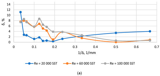
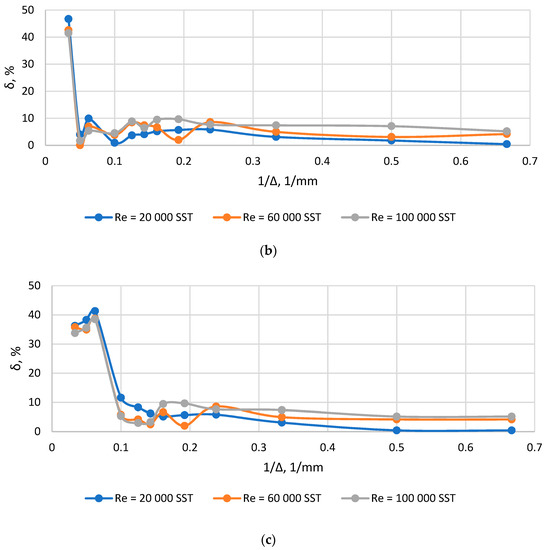
Figure 5.
Plots δ(1/Δ) for channel with sudden expansion: (a) F0/F1 = 0.1; (b) F0/F1 = 0.3; (c) F0/F1 = 0.5.
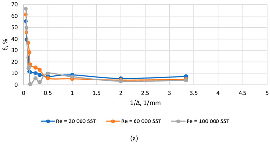
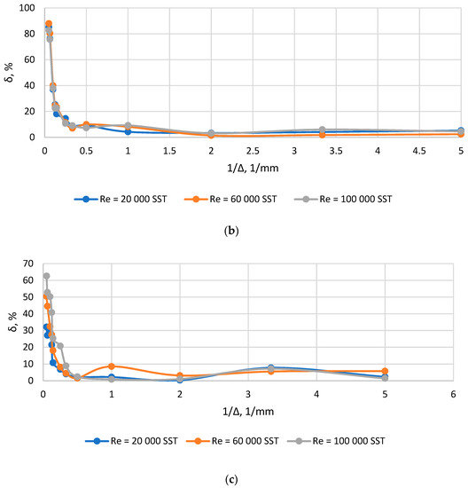
Figure 6.
Plots δ(1/Δ) for channel with sudden contraction: (a) F0/F1 = 0.1; (b) F0/F1 = 0.3; (c) F0/F1 = 0.5.
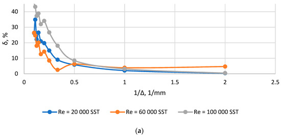
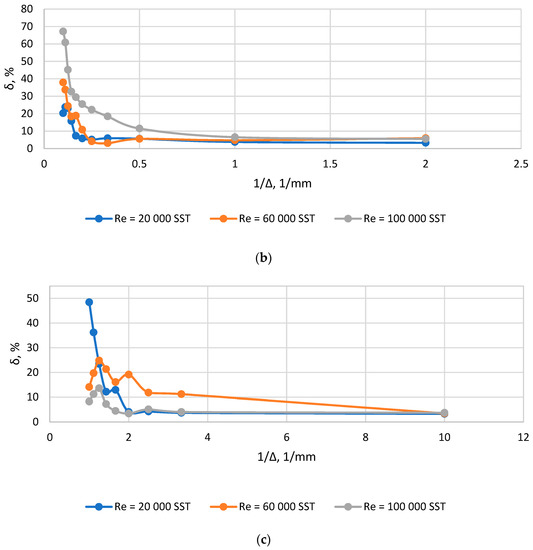
Figure 7.
Plots δ(1/Δ) for diffuser: (a) F0/F1 = 0.1; (b) F0/F1 = 0.3; (c) F0/F1 = 0.5.
According to the results of research on grid convergence for each of the channels under consideration for the considered modes, the sizes of global elements were found that ensure grid convergence, after which these sizes were reduced to a dimensionless form to obtain the value of the parameter Ko. The results of data processing are shown in Table 4. In some cases, the smaller grid leads to a local decrease in accuracy. It can be related to the changing of the aspect ratio of the global element and near-wall element, and also, it can be related to local errors within the convergence process. This effect should be considered in detail in further studies.

Table 4.
Grid convergence data for the considered single channels.
The correlations obtained during the correlation analysis are shown in Figure 8 and Table 5. As can be seen from Figure 8, the correlation for each type of channel has its own slope, while all correlations are statistically significant. Correlations at low Re have a small slope angle, from which we can conclude that in this zone, approximately the same number of layers is needed to resolve the logarithmic boundary layer. At high values of Re’, which corresponds to the transition to developed turbulence, the ratio of the size of the optimal element to the thickness of the boundary layer increases at a faster rate, which indicates that in this zone a smaller number of elements is required to resolve the logarithmic boundary layer, which can be explained on average the smaller contribution of the wall to the flow pattern under these regimes. The overall correlation that unites the points for all the considered geometries also has statistical significance and is quite strong.
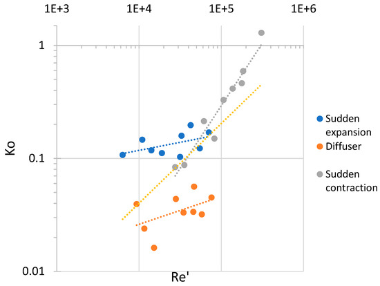
Figure 8.
Correlations Ko(Re′) for the considered geometries.

Table 5.
Parameters of developed correlations.
In the overall correlation, the power at Re′ is 0.762, while the thickness of the boundary layer is proportional to Re′−13/14, which indicates that the element size increases more slowly than the thickness of the boundary layers, so that higher Re corresponds to a smaller element size, which is a physical result.
To check the adequacy of the overall correlation, parametric calculations of the compound channel were carried out at different Reynolds numbers at the input. During validation, for each Re, Re’ was found to correspond to the average channel diameter, after which, using correlations, the number Ko was found, from which the linear size of the global grid element was expressed. Using the element size estimated a priori from correlations, a grid is constructed similarly to the considered channels. According to the results of calculations, the values of the control parameter corresponding to the literature data with an acceptable accuracy of 10%. The calculation results are shown in Figure 9.
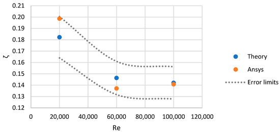
Figure 9.
Graph of the coefficient of hydraulic resistance of the compound channel from the Reynolds number.
Thus, based on the results of the calculations of the compound channel, it can be concluded that the proposed ratios are generally adequate in relation to channels containing diffuser sections, sudden expansion and the contraction, since when modeling the compound channel, the correlations predict with acceptable accuracy the value of the element size that provides the necessary calculation accuracy. If the correlations do not provide the required accuracy, the values obtained from them can be used as a first approximation in the study of grid convergence.
5. Conclusions
Based on the results of the simulation of turbulent flows in typical channels, as well as the analysis of the calculated data, the following conclusions can be drawn:
- There are regularities that relate the size of the grid model element, which ensures convergence along the grid, with the regime and geometric parameters of the flow in the channel;
- As a dimensionless similarity criterion, one can introduce the coefficient Ko, the ratio of the size of the grid model element that ensures grid convergence to the thickness of the turbulent boundary layer;
- There are statistically significant correlations Ko(Re’) for channels with sudden expansion, sudden contraction and diffusers, and there is also an overall statistically significant correlation Ko(Re’);
- This correlation makes it possible to a priori estimate the required size of the grid model element, including for compound channels, the simulation results using the obtained grid settings are within acceptable limits compared to the literature data.
Author Contributions
Conceptualization, S.O. and I.K.; methodology, P.B. and N.R.; software, P.B.; validation, P.B. and S.O.; formal analysis, A.R.; investigation, A.R.; resources, N.R. and I.K.; data curation, N.R.; writing—original draft preparation, P.B.; writing—review and editing, A.R.; visualization, P.B.; supervision, S.O.; project administration, I.K.; funding acquisition, N.R. All authors have read and agreed to the published version of the manuscript.
Funding
This study conducted by the Moscow Power Engineering Institute was financially supported by the Ministry of Science and Higher Education of the Russian Federation (project no. FSWF-2020-0020).
Data Availability Statement
Not applicable.
Conflicts of Interest
The authors declare no conflict of interest.
References
- Moin, P.; Mahesh, K. DIRECT NUMERICAL SIMULATION: A Tool in Turbulence Research. Annu. Rev. Fluid Mech. 1998, 30, 539–578. [Google Scholar] [CrossRef]
- Fransen, R.; Morata, E.C.; Duchaine, F.; Gourdain, N.; Gicquel, L.Y.M.; Vial, L.; Bonneau, G. Comparison of RANS and LES in High Pressure Turbines. In Proceedings of the 3Me Colloque INCA, ONERA, Toulouse, France, 17–18 November 2011; pp. 1–15. [Google Scholar]
- Che Sidik, N.A.; Yusuf, S.N.A.; Asako, Y.; Mohamed, S.B.; Aziz Japa, W.M.A. A Short Review on RANS Turbulence Models. CFDL 2020, 12, 83–96. [Google Scholar] [CrossRef]
- Spalart, P. Detached-Eddy Simulation. Annu. Rev. Fluid Mech. 2009, 41, 181–202. [Google Scholar] [CrossRef]
- Goldberg, U.; Peroomian, O.; Chakravarthy, S. Application of the K-Epsilon-R Turbulence Model to Wall-Bounded Compressive Flows. In Proceedings of the 36th AIAA Aerospace Sciences Meeting and Exhibit; American Institute of Aeronautics and Astronautics, Reno, NV, USA, 12 January 1998. [Google Scholar]
- Wilcox, D.C. Formulation of the K-w Turbulence Model Revisited. AIAA J. 2008, 46, 2823–2838. [Google Scholar] [CrossRef]
- Menter, F.R. Two-Equation Eddy-Viscosity Turbulence Models for Engineering Applications. AIAA J. 1994, 32, 1598–1605. [Google Scholar] [CrossRef]
- Zhiyin, Y. Large-Eddy Simulation: Past, Present and the Future. Chin. J. Aeronaut. 2015, 28, 11–24. [Google Scholar] [CrossRef]
- Popov, G.; Matveev, V.; Baturin, O.; Novikova, Y.; Volkov, A. Selection of Parameters for Blade-to-Blade Finite-Volume Mesh for CFD Simulation of Axial Turbines. MATEC Web Conf. 2018, 220, 03003. [Google Scholar] [CrossRef][Green Version]
- Lu, Z.; Piro, M.H.A.; Christon, M.A. Mesh and Turbulence Model Sensitivity Analyses of Computational Fluid Dynamic Simulations of a 37M CANDU Fuel Bundle. Nucl. Eng. Technol. 2022, 54, 4296–4309. [Google Scholar] [CrossRef]
- Osipov, S.; Shcherbatov, I.; Vegera, A.; Bryzgunov, P.; Makhmutov, B. Computer Flow Simulation and Verification for Turbine Blade Channel Formed by the C-90-22 A Profile. Inventions 2022, 7, 68. [Google Scholar] [CrossRef]
- Sadrehaghighi, I. Mesh Sensitivity & Mesh Independence Study; CFD Open Series: Annapolis, MD, USA, 2021; p. 56. [Google Scholar]
- Balduzzi, F.; Bianchini, A.; Ferrara, G.; Ferrari, L. Dimensionless Numbers for the Assessment of Mesh and Timestep Requirements in CFD Simulations of Darrieus Wind Turbines. Energy 2016, 97, 246–261. [Google Scholar] [CrossRef]
- Ben-Mansour, R.; Al-Hadhrami, L. Effect of Reynolds Number and Property Variation on Fluid Flow and Heat Transfer in the Entrance Region of a Turbine Blade Internal-Cooling Channel. Int. J. Rotating Mach. 2005, 2005, 36–44. [Google Scholar] [CrossRef]
- Komarov, I.; Osipov, S.; Vegera, A.; Kharlamova, D.; Zonov, A. Verification of Computer Flow Simulation in Confuser and Diffuser Channels. In Proceedings of the International Symposium on Sustainable Energy and Power Engineering 2021, Singapore, 18–21 December 2021; Irina, A., Zunino, P., Eds.; Lecture Notes in Mechanical Engineering. Springer Nature Singapore: Singapore, 2022; pp. 343–352, ISBN 9789811693755. [Google Scholar]
- Rogalev, A.N.; Kindra, V.O.; Osipov, S.K.; Makhmutov, B.A.; Zonov, A.S. Numerical Research of the Influence of the Geometric Parameters of Shadowing Fins on the Intensity of Jet Cooling by Supercritical Carbon Dioxide. J. Phys.: Conf. Ser. 2020, 1683, 022050. [Google Scholar] [CrossRef]
- Salim, S.M.; Cheah, S.C. Wall Y+ Strategy for Dealing with Wall-Bounded Turbulent Flows. In Proceedings of the International MultiConference of Engineers and Computer Scientists 2009 Vol IIIMECS 2009, Hong Kong, 18–20 March 2009; pp. 1–6. [Google Scholar]
- Nagib, H.M.; Chauhan, K.A.; Monkewitz, P.A. Approach to an Asymptotic State for Zero Pressure Gradient Turbulent Boundary Layers. Phil. Trans. R. Soc. A. 2007, 365, 755–770. [Google Scholar] [CrossRef] [PubMed]
- Kline, S.J.; Reynolds, W.C.; Schraub, F.A.; Runstadler, P.W. The Structure of Turbulent Boundary Layers. J. Fluid Mech. 1967, 30, 741–773. [Google Scholar] [CrossRef]
- Handbook of Hydraulic Resistance; The National Science Foundation: Washington, DC, USA, 2008; p. 526.
- Rodgers, J.L.; Nicewander, W.A. Thirteen Ways to Look at the Correlation Coefficient. Am. Stat. 1988, 42, 59–66. [Google Scholar] [CrossRef]
Disclaimer/Publisher’s Note: The statements, opinions and data contained in all publications are solely those of the individual author(s) and contributor(s) and not of MDPI and/or the editor(s). MDPI and/or the editor(s) disclaim responsibility for any injury to people or property resulting from any ideas, methods, instructions or products referred to in the content. |
© 2022 by the authors. Licensee MDPI, Basel, Switzerland. This article is an open access article distributed under the terms and conditions of the Creative Commons Attribution (CC BY) license (https://creativecommons.org/licenses/by/4.0/).