Article

Control on Flow Separation over a Cylinder by a Ferrofluid Film Adsorbed by a Magnet

1
State Key Laboratory of Engines, School of Mechanical Engineering, Tianjin University, Tianjin 300350, China
2
School of Chemical Engineering and Technology, Tianjin University, Tianjin 300350, China
*
Authors to whom correspondence should be addressed.
Inventions 2024, 9(3), 65; https://doi.org/10.3390/inventions9030065
Submission received: 30 April 2024 / Revised: 27 May 2024 / Accepted: 3 June 2024 / Published: 4 June 2024

Abstract

:
Flow separation can lead to increased resistance and vibration generation, which is a difficult problem that cannot be ignored in engineering. In this paper, we propose a method of controlling flow separation by adsorbing ferrofluid onto the surface of a magnetized cylinder, taking the common flow around a cylinder as an example. Parametric effects of the ferrofluid film, including its viscosity and thickness, on the flow behavior were investigated in terms of the vortex shedding process, velocity distribution, dominant frequency, pressure distribution, and the flow motion inside the ferrofluid film. The results indicate that the ferrofluid film can suppress the generation of flow separation and achieve effective control, which is mainly caused by wall slip and the internal movement of the ferrofluid film. Furthermore, the flow separation control effect of ferrofluid thin films with different parameters varies, with low-viscosity ferrofluid exhibiting a superior control effect.

1. Introduction

When fluid moves relative to a solid surface, a boundary layer forms and viscous forces act on the fluid near the surface. Flow separation from the solid surface often induces significant drag resistance, fluctuating lift force, structure vibration, and severe energy loss. Efficient control or elimination techniques of flow separation have long been the pursued target of engineers in various fields, such as chemical engineering, construction, water conservancy, marine engineering, and so forth [1,2,3,4]. So far, numerous techniques have been proposed to control or suppress flow separation, which can be generally divided into active and passive control techniques according to whether the external forces are exerted [5].
A passive flow control technique is mainly carried out by modulating the surface structure and geometry, such as applying surface grooving, attachment mounting, bionic structures, and so forth. For instance, Lee et al. achieved a 10% drag reduction in the vortex region by using a V-shaped notch on the surface of a cylinder, and they pointed out that the enhancement of a viscous-free fluid into the wake region is responsible for the achieved drag reduction [6,7]. Later, they found that spiral grooves are more effective in reducing the amplitude of vortex-induced microflow vibrations, which can reach 64% under proper conditions [8]. Wang et al. adopted slits to suppress the flow separation and found slits can destroy the extensive large-scale disordered vorticity induced by the pressure-side smooth airfoil to small-scale vortices induced by the coupled airfoil, which reduces the turbulence kinetic energy (TKE) generated during the flow separation [9]. In addition, the attachment mounting method can also suppress vortex generation as the interaction of the top and bottom sides of the shear layer. Gao et al. discovered that by mounting the attachment in a way that moves the interaction of vortex tails downstream, the vortex sheet elongates, and the TKE is significantly reduced [10]. In addition to the grooves and the attachment, inspired by the silent flight and furry surfaces of birds, flow control methods for soft surfaces and furry brush-like structures are beginning to receive attention. Deng et al. designed a soft wake band that alters the vortex structure by separating the lower shear layer [11]. Brücker et al. found that furry surfaces reduce turbulent drag [12], and Hasegawa found that microfiber coatings delay flow separation [13]. Lin et al. proposed an adaptive furry microfiber surface drag reduction based on these experiences and found that nylon threads with appropriate lengths completely inhibit the trailing vortex shedding mode of the Kármen vortex street [14]. This passive control mechanism operates by utilizing nylon wires to elongate the unstable shear layer on both sides of the cylindrical model, thereby augmenting the length of vortex formation and propelling the vortex structure further downstream. The wake vortex shedding pattern of the Kárman vortex street is then suppressed.
The passive control techniques described above, although characterized by simplicity of operation and energy savings, are highly susceptible to vandalism and have the disadvantage of being extremely inflexible. They need to be designed specifically to cope with different surfaces. Active control, on the other hand, can actively change the flow by consuming external energy and controlling the system, which is adjustable and adaptable, responding and adjusting in real time as needed. It can be optimized for specific needs and provide more precise flow control. Nowadays, active flow control can be achieved by external energy input, such as rotating circular cylinders, surfactant release, microbubble method, magnetic fluid coating [15,16], and so forth. For example, the rotation of a circular cylinder changes the flow characteristics drastically, especially at high rotation rates. Tokumaru and Dimotakis achieved flow control by using a high-speed rotating cylinder. They discovered that the cylinder’s rotation disrupted the symmetry of the wake flow, effectively controlling the process of vortex shedding [17]. Lam et al. found that as the rotational speed of the cylinder increases, the wake becomes narrower and deflected to the side, and the length of the vortex becomes smaller [18]. This leads to a slight increase in the frequency of vortex shedding. However, their efficiency is not particularly high. Releasing viscoelastic fluids near the turbulent boundary layer is also an active control method. In 1949, Toms reported the turbulence-damping effect of dilute solutions of polymers [19]. In the 1970s, surfactants with non-Newtonian fluid properties (later called viscoelastic fluids) were also found to reduce turbulent drag. This method provides high economic and environmental benefits in reducing drag and increasing transport in pipelines such as heating and cooling pipelines [20]. The active drag reduction by viscoelastic fluid can be achieved by continuously injecting viscoelastic fluid from both sides of the wall [21]. The microbubble method is another type of active control technique where drag reduction is achieved by somehow generating microbubbles and distributing them on the cylindrical surface to change the flow in the boundary layer. A large number of experiments have verified the drag-reduction performance of microbubbles. Bubble sizes in the tens of microns have a better drag-reduction effect [22,23]. A significant drag-reduction effect can be achieved by generating a large number of bubbles and making them stably attached within the turbulent boundary layer. The generation of microbubbles can be obtained by electrolysis, coating, and air jet methods, but all these microbubble generation methods require the installation of specific equipment.
However, it is notable that the above active control techniques consume a large amount of external energy. Drag reducers are difficult to maintain on the surface, which requires the constant release of liquid to form a liquid film and a dedicated space within the wall to store them. If applied to a navigational body, it would result in a significant reduction in space utilization, offsetting the economic benefits of drag reduction, and would be prone to impacts on the surrounding environment. Different from the above−mentioned methods, Krakov proposed the concept of magnetic fluid coating in 1984 and found that this method has a positive effect on the free flow structure [24]. Moreover, Krakov and Kamiyama systematically studied the changes in the flow field structure and the drag-reduction effect when a circle cylinder was coated with the magnetic fluid. The results showed that the magnetic fluid layer could effectively prevent flow separation and the drag-reduction effect determined by the viscosity ratio between the magnetic fluid and the outer fluid [25]. Stancanelli et al. reported a drag-reduction technique involving a ferrofluid drag-reduction method using a permanent magnet-adsorbed ferrofluid to form a liquid film as a smooth surface to achieve wall slip, which reduced the drag in the inner pipe by more than 80% [26]. However, the stability of the magnetic fluid layer around the solid wall is a key factor in limiting the application of magnetic fluid coating. Krakov et al. experimentally investigated the stability of kerosene-based magnetic fluid in a glass tube. The results showed that the magnetic fluid layer waves became greater and even broke off as flow rates increased [27].
Above all, most scholars paid more attention to the qualitative analysis and the explanation of the flow control mechanism and less to the analysis of quantitative parameters. In this paper, we investigate the flow control effect of ferrofluid in external flow. To this end, the control performance of ferrofluid film for the flow separation over a cylinder is evaluated. A thin film of ferrofluid is absorbed on a cylinder magnet to alter the flow characteristics. This paper mainly examines the parametric effect including the viscosity and the thickness of the ferrofluid film on the flow performance such as pressure distribution, vortex shedding frequency, and so forth. Additionally, the flow motion inside the ferrofluid film is also investigated to understand the ferrofluid effect on flow separation.

2. Materials and Methods

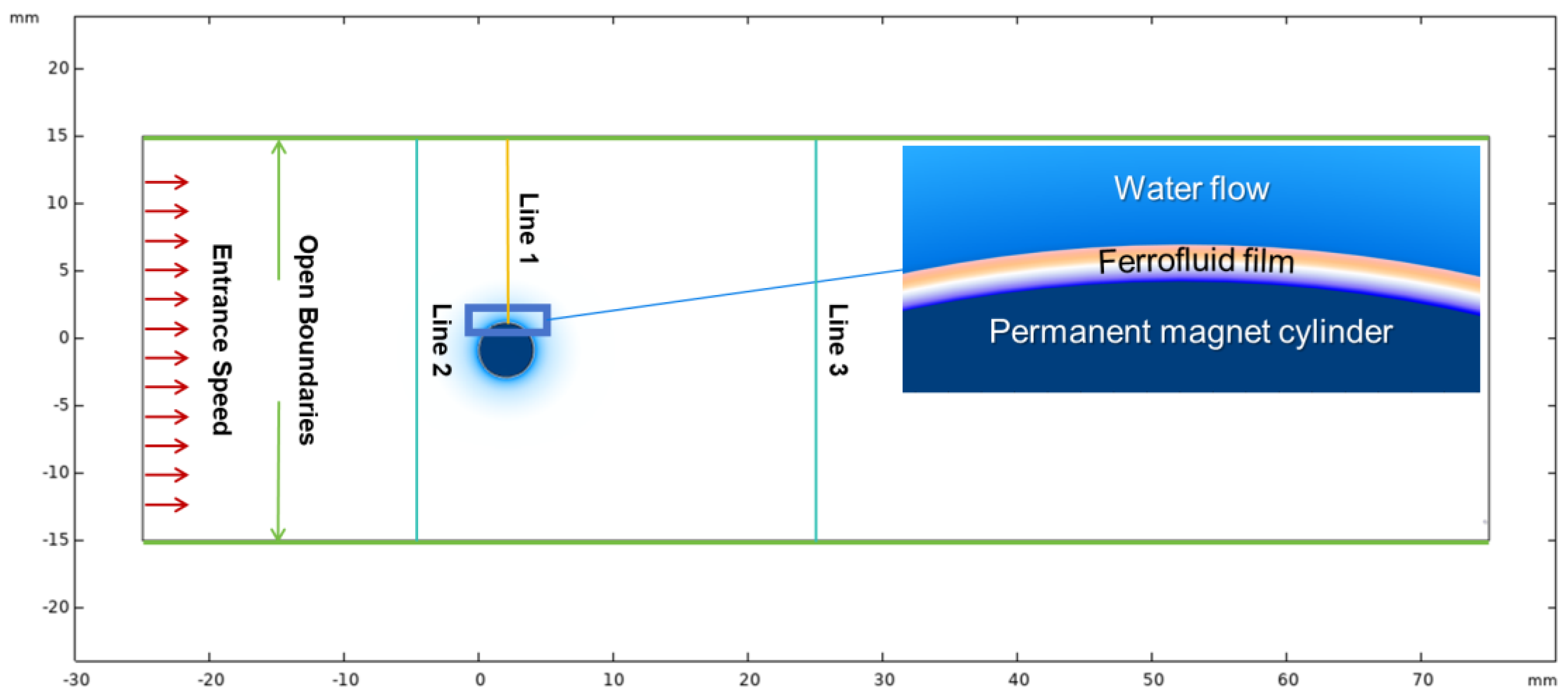
2.1. Flow Configuration

Figure 1 illustrates the flow configuration, which consisted of three domains: a permanent magnet cylinder, a ferrofluid wrapped around the cylinder with a certain thickness, and a domain of water flow. In this case, the radius of the cylinder with magnetism was set to 2.0 mm; the thickness of the ferrofluid wrapped around the cylinder was set to 0.05 mm, 0.10 mm, and 0.15 mm, respectively; the length of the water basin was 100 mm, and the width was 30 mm. To ensure simplicity and validity, we made the following assumptions during the numerical simulations: (1) the flow was assumed to be incompressible; (2) there was no mass transfer between the ferrofluid and water; (3) changes in fluid properties due to temperature were not considered; and (4) the gravitational force was neglected.
Table 1 shows the detailed properties of ferrofluid. In this study, we chose the ferrofluid to be an oil phase liquid immiscible with water, and the surface tension between the ferrofluid and water was set to be 0.18 N/m. The cylinder was set to be a nonslip wall. In addition, the left boundary was the inlet with constant entrance velocity, the right boundary was the outlet with the atmosphere pressure, and the upper and lower boundaries were open boundaries. Table 2 displays the flow conditions applied in the simulation. The Reynolds number (Re) is defined by R e = ρ u D / μ , where ρ is the fluid density, u is the incoming velocity, D is the cylinder diameter, and μ is the fluid viscosity; Δ represents the thickness of the ferrofluid film.

2.2. Numerical Method

To track the interface movement and the phase distributions in two fluids, we used the level-set method in this study. The level-set method is known for its ability to capture interface curvature accurately and good conversation, which is crucial in analyzing thin ferrofluid films [28,29]. In this method, the phase field ϕ is used to denote the volume ratio of the ferrofluid, assuming two distinct values, namely ϕ = 1 to characterize the water phase and ϕ = 0 for the ferrofluid phase. The interface between the two mediums is represented by ϕ = 0.5. The level-set equation is as follows:
ϕ t + u ϕ = γ ( ε l s ϕ ϕ 1 ϕ ϕ ϕ )
where ε l s is the thickness of the interface. Here, we set ε l s to be equal to half of the largest mesh size in the computational domain to ensure simulation accuracy and make sure it is much smaller than the thickness of the ferrofluid film [30]. Additionally, γ represents the reinitialization parameter. Large values of the γ lead to calculation errors, while small values of γ create interface instability. Consequently, in this study, γ was determined by the maximum fluid velocity in the fluid field [28].
The two-phase flow can be described by the incompressible Navier–Stokes equation, which incorporates supplementary force terms in addition to the body force resulting from the magnetic field and surface tension. The governing equation is as follows:
ρ i u t + ρ i u u = p I + σ + f s + f k ρ i u = 0
where u represents the velocity of the fluid, p represents the pressure exerted on the fluid, and σ = μ i ( u + ( u ) T ) represents the viscous shear stress. The effective density ρi and dynamic viscosity μi are, respectively, defined as follows:
ρ i = ρ m + ρ w ρ m ϕ
μ i = μ m + μ w μ m ϕ
where w represents the water field, and m represents the ferrofluid field. In addition, f s is the surface tension exerted on the interface between the ferrofluid phase and the water phase, and magnetic stress is in the form of the volume force, namely f k , which is calculated using the following equation:
f K = μ 0 ( M ) H + μ 0 2 × ( M × H )
where M is the fluid magnetization, and H represents the magnetic field strength. The fluid magnetization M can be solved as follows:
M = χ H
where χ represents the magnetic susceptibility of the fluid. In natural and thermomagnetic convection, the fluid velocity is low, and a steady-state magnetic field is applied. Therefore, it can be assumed that the magnetic moment is always aligned with the external magnetic field, and there is no magnetic dissipation in the fluid. Consequently, the last term in Equation (5) can be neglected [31]. The process of ferrofluid adsorption was simulated using the volume force in the magnetic field-coupled laminar flow. The magnet used in this case, like most magnets, was nonconductive. Maxwell’s system of equations can be simplified as follows:
× H = 0 B = 0
where B represents the strength of the magnetic induction. In the ferrofluid field, magnetic induction and magnetic field can be calculated as follows:
B = μ 0 ( 1 + χ ) H
where μ0 is the vacuum permeability and has the value 4π × 10−7 H/m. In this study, the cylinder was assumed to be a permanent magnet, with the constitutive relation defined by its remanent flux density, expressed as follows:
B = μ 0 1 + χ H + B r
where B r is the remanent flux density of the permanent magnet after the removal of an external magnetic field, and it is defined as follows:
B r = B r e e
where e represents the direction of the magnetic field. The influence of ferrofluid on the magnetic field was ignored [28].

2.3. Numerical Procedures

The numerical models were solved using COMSOL Multiphysics 6.1, involving two main steps: phase initialization and transient calculation. Phase initialization utilizes steady-state equations for laminar flow, magnetic field, and level-set function, while transient calculation employs their respective transient equations. To manage the fluid flow and the two-phase interface movement, we utilized the coupling of the laminar flow field and the level-set method. In this study, the permanent magnet cylinder employed the remanent flux density constitutive relation as depicted in Equation (9). The value of B r was set to 250 mT, oriented along the y-axis. The resulting magnetic field distribution is illustrated in Figure 2.
To guarantee the convergence and the accuracy of transient numerical simulations, a fine mesh was used to capture the phase interface, which was refined at the phase interfaces of ferrofluid and water. The grid independence validation was first performed. Considering a ferrofluid with μ = 0.6 Pa·s and Δ = 0.1 mm, the mesh with 53,750 domain cells and 864 boundary cells was used. Moreover, a small time step of 0.001 s was used during the transient simulation, and a tolerance of 10−6 was set to ensure convergence of the numerical results. To verify the reliability of the current numerical simulation, we calculated the Strouhal number (St) for the case of Re = 300 and compared it with the ones obtained using the empirical formula proposed by Norberg [32]. The comparison results are shown in Table 3. It can be concluded that the error is just 0.79%, indicating that the chosen numerical model and simulation method are reliable.

3. Result and Analysis

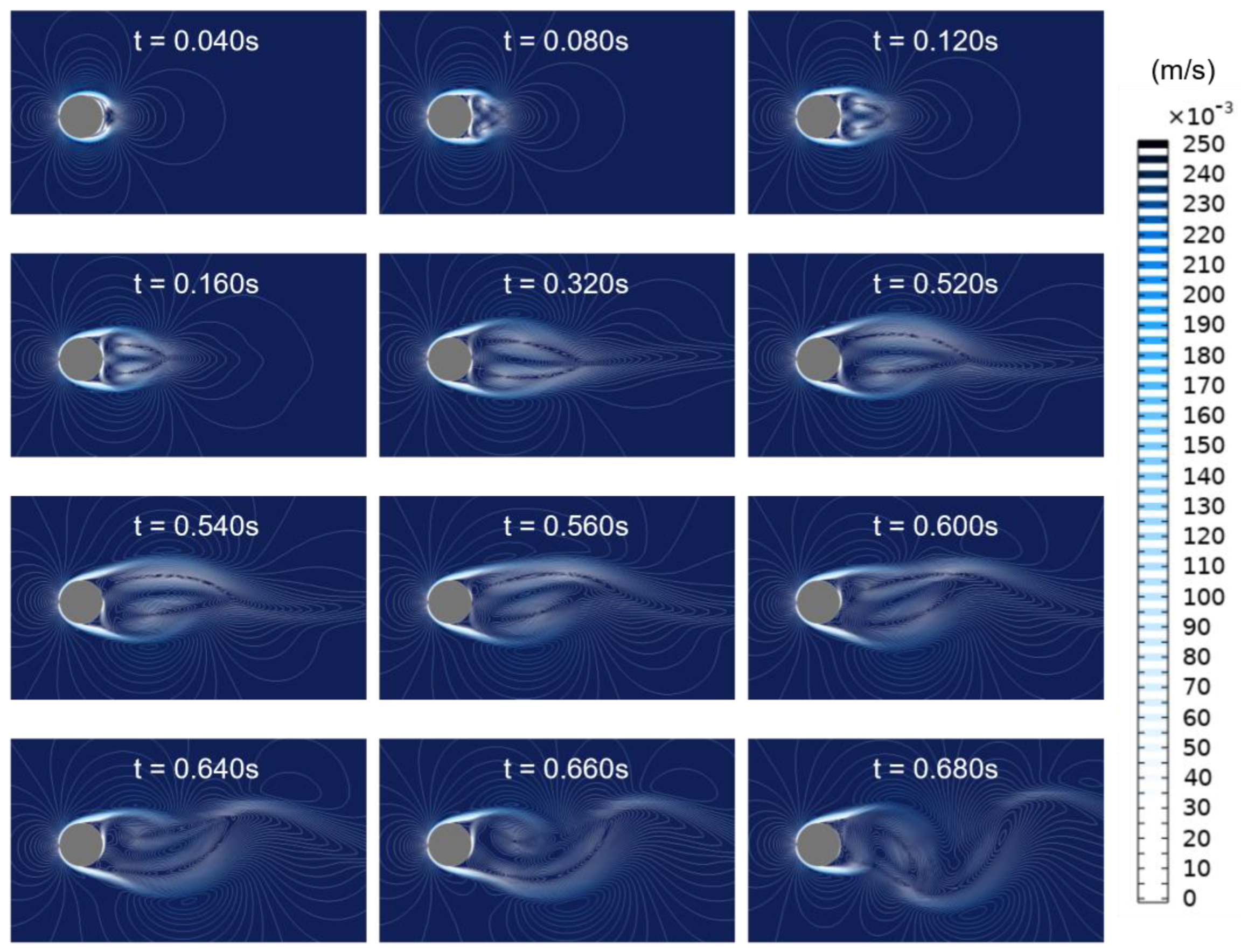
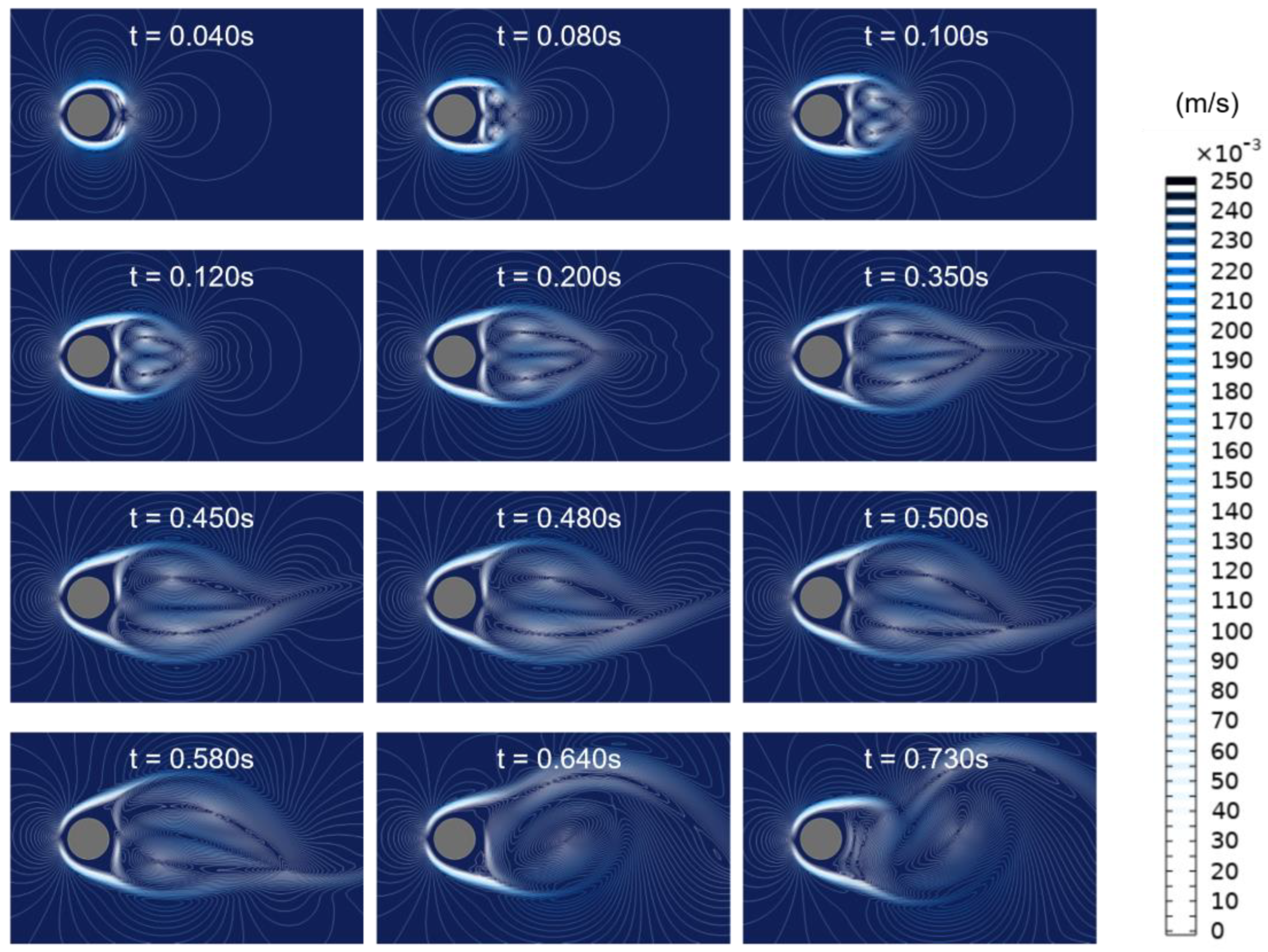
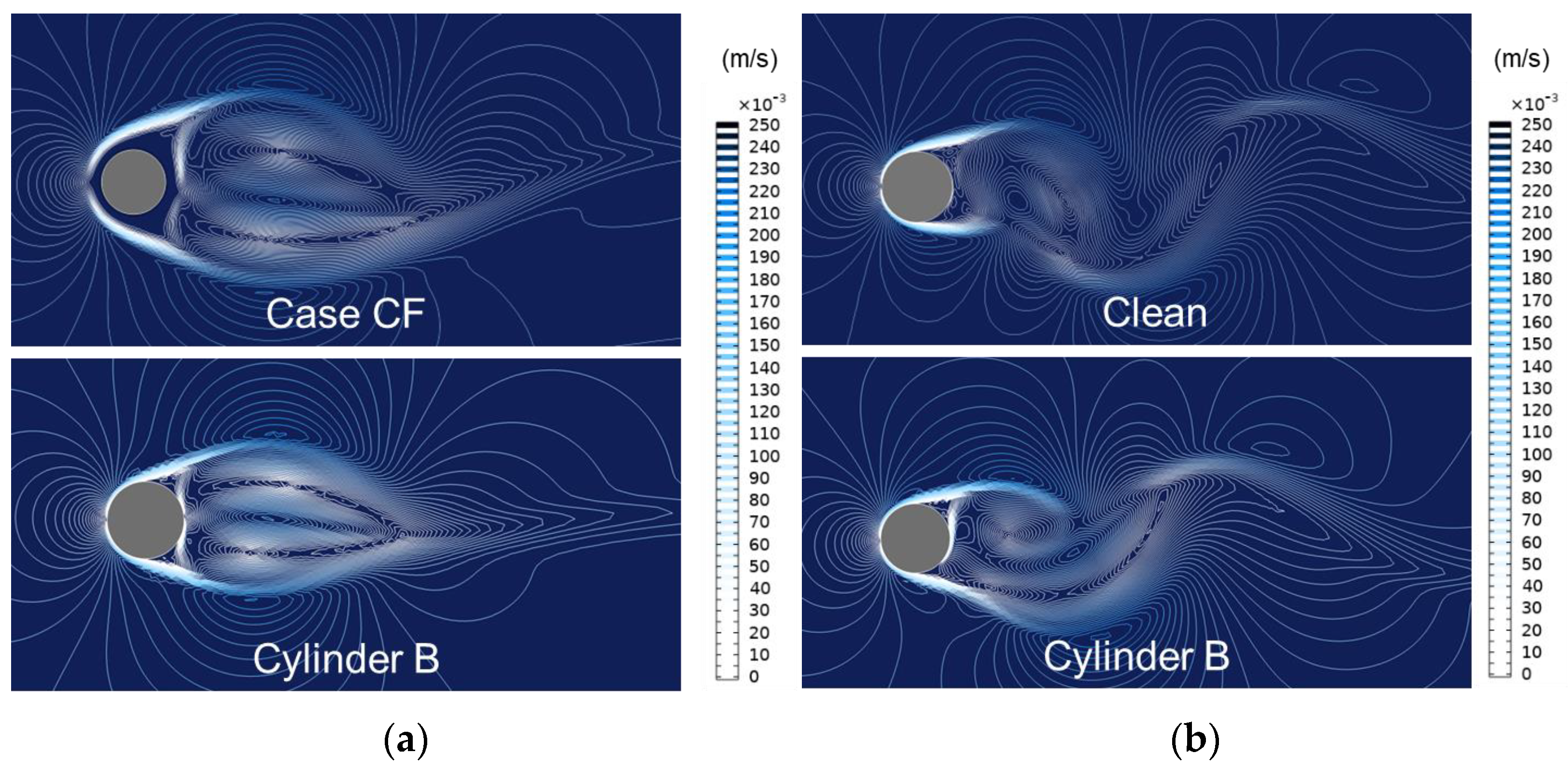
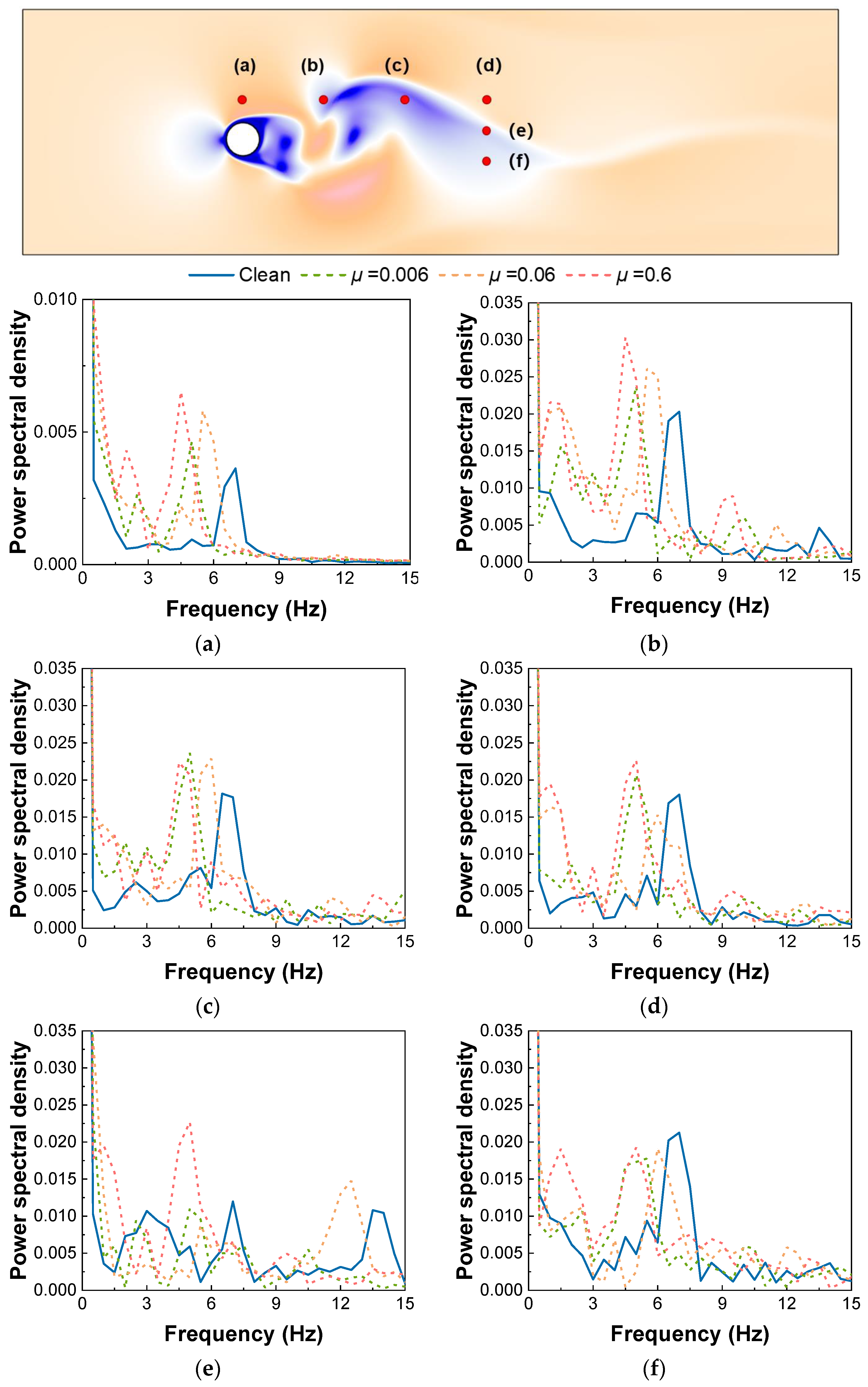
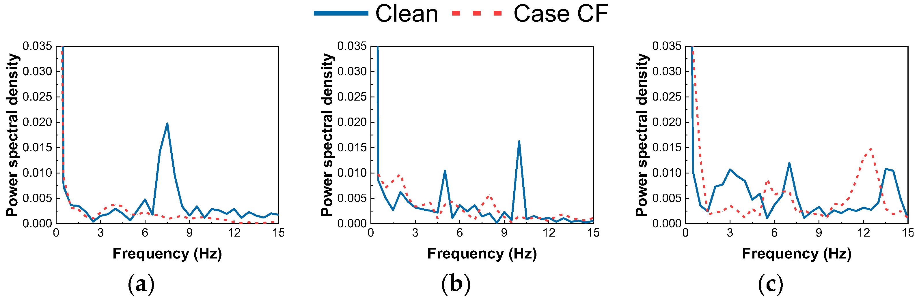
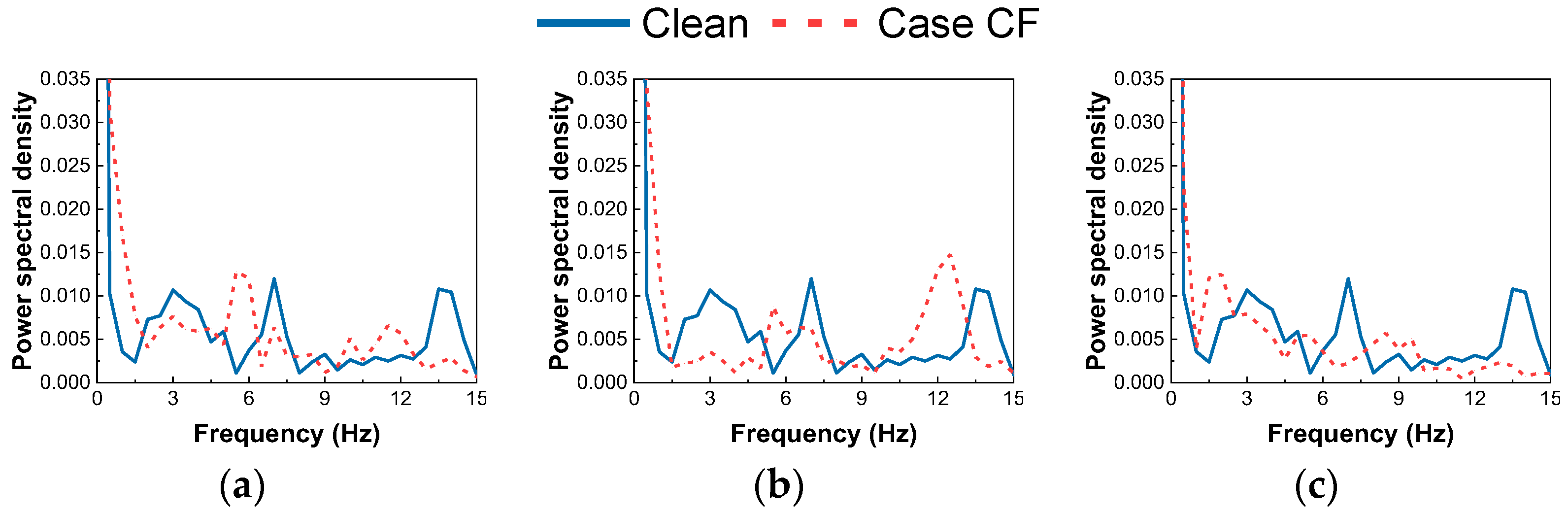
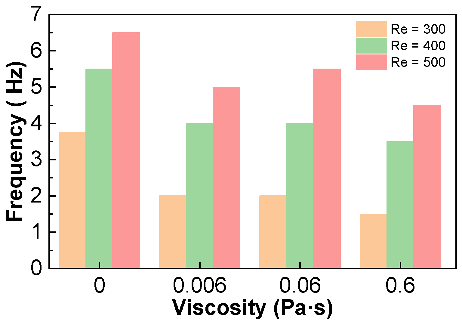
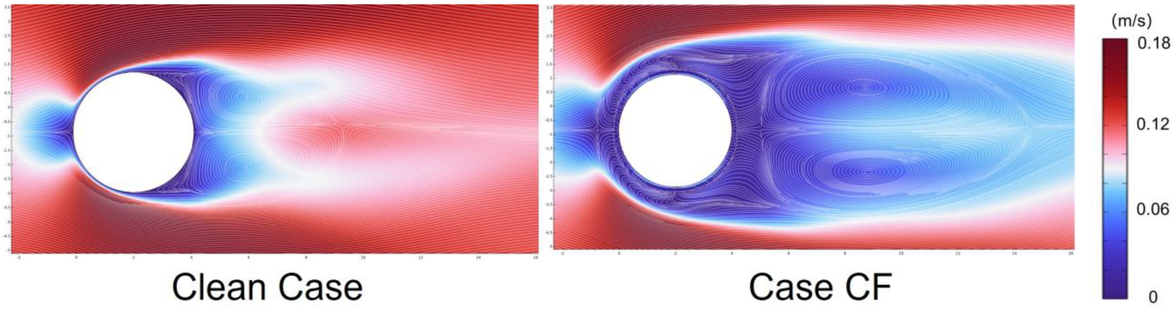
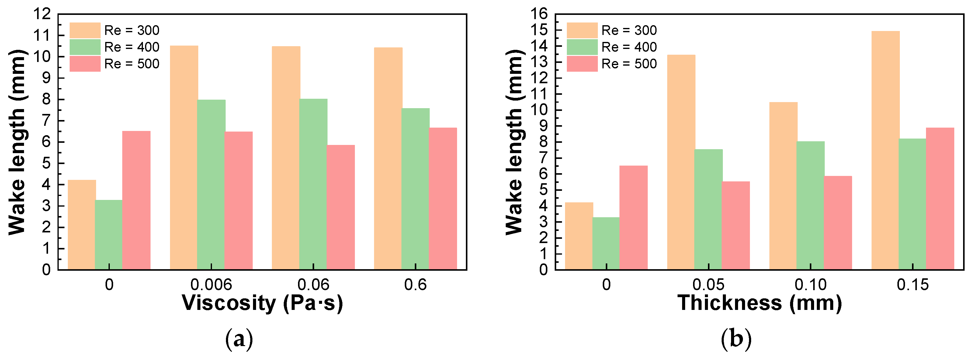
3.1. Vortex Shedding Process

Firstly, to have an intuitive image of the ferrofluid film effect on the flow, we analyzed the vortex shedding process for the clean cylinder (clean case) and the cylinder wrapped with ferrofluid film (CF case), as illustrated in Figure 3 and Figure 4. Here, the case with Δ = 0.1 mm at Re = 500 is chosen as an example. This process begins by observing the formation of two symmetric vortices in the wake of the cylinder. The edge length of these vortices increases with time. Subsequently, a vortex is formed in the center of the wake and is gradually elongated and compressed as the tail flow swings downward. Then, the vortex detaches from the wake during its upward swings. This entire process takes approximately 0.68 s for the clean cylinder. The process of vortex shedding in the presence of ferrofluid film is similar to that in the clean cylinder case, as shown in Figure 4. However, given the same initial condition, the width and the length of the wake increase significantly, leading to a larger vortex area and longer vortex shedding time by about 0.05 s delayed compared to the clean case cylinder.
Two factors, i.e., slightly larger cylinder diameter and the slip effect induced by the ferrofluid film, could be responsible for the different behaviors of the vortex shedding. To clarify whether the formation of ferrofluid-induced vortices is due to a slight increase in diameter, we conducted a control test using a clean cylinder with a diameter of 2.1 mm (named Cylinder B), which was equal to the diameter of the ferrofluid-wrapped cylinder. Figure 5 compares the vortex behavior for the clean cylinder cases with different diameters and the case of a ferrofluid-wrapped cylinder. It can be observed that in spite of the same overall diameter, the wake size of Cylinder B is still significantly smaller than that of the ferrofluid-wrapped cylinder case in Figure 5a. Little difference can be found in the first vortex shedding time between the cylinder with a diameter of 2.1 mm and the smaller cylinder with a diameter of 2.0 mm, as shown in Figure 5b. Therefore, we argue that the different behaviors of vortex shedding do not originate from the increase in the cylinder diameter but from the additional effect induced by the ferrofluid film.
Furthermore, to quantify the ferrofluid film effect on the vortex shedding, Figure 6 illustrates the energy spectrum in the frequency domain by fast Fourier transform (FFT) of the velocity signal at different locations and flow conditions. Here, six locations correspond to the points at (2, 4), (12, 4), (22, 4), (32, 4), (32, 0), and (32, −4). Figure 7a–c focus on the comparison between the ferrofluid-wrapped case of μ = 0.06 Pa·s and Δ = 0.1 mm and the clean case for different Re at the location of (32, 0). As can be seen, the existence of ferrofluid film leads to a significant reduction in the dominant frequency at all six locations compared with those of the clean cases at all Re, and this effect is stronger for ferrofluid films with viscosities of 0.006 Pa·s and 0.6 Pa·s. To more intuitively characterize the effect of the ferrofluid film on the lift fluctuations, we collected data on the lift coefficient CL of the cylinder for different cases and calculated its dominant frequency. Here, the dominant frequency is the frequency with the largest amplitude in the energy spectrum of the lift coefficient.
Figure 8 analyzes the thickness effect of ferrofluidic film on the suppression of vortex shedding under different conditions. It can be observed that as the ferrofluid thickness increases, the dominant frequency distribution of vortex shedding becomes more focused, with a tendency for the dominant frequency to decrease. Among them, the thickness of 0.15 mm demonstrates the most effective suppression of vortex shedding. Figure 9 further demonstrates the effects of ferrofluid viscosity on the dominant frequency of the lift coefficient. An apparent decrease in dominant frequency can be observed. After further calculations, we observed about 15.38% to 46.81% of the lift coefficient’s dominant frequency attenuation effect.

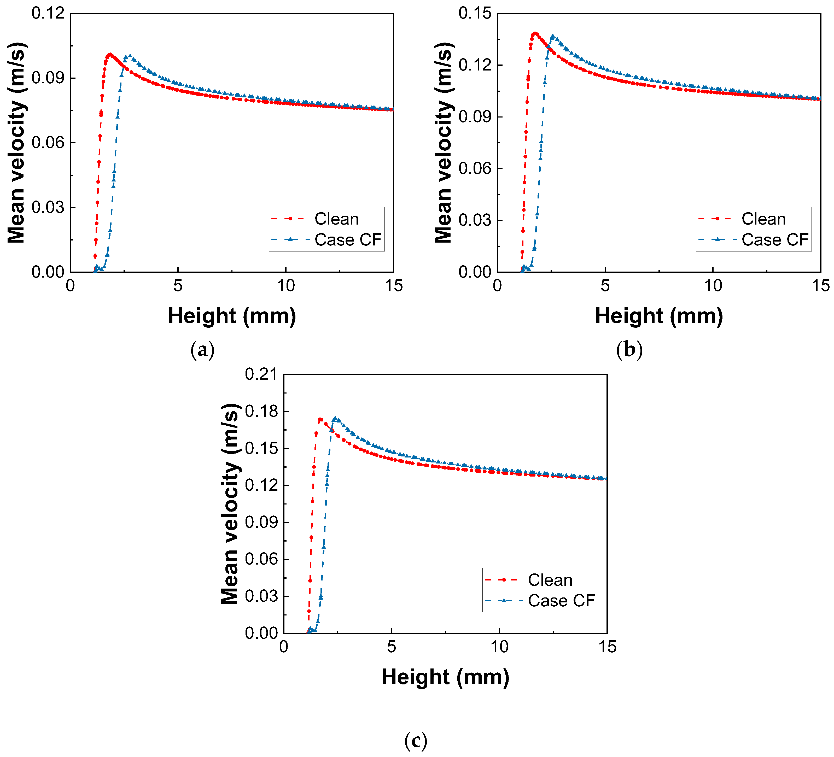
3.2. Velocity Distribution

We then evaluated the ferrofluidic film effect on the wake size. Figure 10 illustrates the ferrofluidic film on the temporally averaged velocity field v ¯ at Re =300. Here, v ¯ = 0 T v d t / T , where T is the integrated time. It can be observed that in the clean case, a recirculation region is formed on the lee side of the flow field due to the flow separation on both sides of the cylinder and an upward shift of the vortex separation point. Furthermore, within this region, a pair of vortices is distributed symmetrically around the centerline, and this vortex pair is the main cause of the uneven pressure distribution around the cylinder [14]. Similar flow characteristics appear in the case of a ferrofluid-wrapped cylinder. However, unlike those of clean cases, the length and width of the wake significantly enlarge. The vortices in the wake of the clean case both appear to be squeezed and move downstream. Consequently, the streamline between the wake and the cylinder becomes more regular in the case of ferrofluid-wrapped cylinder. In other words, the existence of the ferrofluid film changes the structure of the flow field and makes the streamline distribution more stable, which suppresses the flow separation. Furthermore, Figure 11 shows the parametric effects, including the viscosities and thickness of ferrofluidic film, on the mean velocity distribution at different Re. As can be seen, the ferrofluid film with lower viscosity and larger thickness is more effective in reducing vortex strength and enlarging the wake region. This is further demonstrated by the viscosity and thickness effect on the wake length, as shown in Figure 12.
Figure 13 further illustrates the temporally averaged velocity profile v ¯ on the vertical line above the cylinder at different Re and ferrofluid properties. As is clearly shown, the v ¯ curve shows a smooth rise in the clean case, whereas in the case of the ferrofluid-wrapped cylinder, the v ¯ curve is divided into two phases: First, v ¯ in the region of the ferrofluid shows an approximation to 0, and then, starting from the interface of the ferrofluid, v ¯ rises sharply, and finally in the case of the ferrofluid-wrapped cylinder, it exceeds the clean case. This means that in the clean case, the fluid shows nonslip behavior on the cylinder wall, whereas in the case of the ferrofluid-wrapped cylinder, a velocity slip exists. The above results are consistent with those reported by Stancanelli et al. [26]. Ferrofluidic films can reduce the shear rate near the wall during fluid flow by introducing velocity slips. To further investigate the effect of the viscosity of the ferrofluid film on the slip phenomenon, we selected ferrofluids with different viscosities to observe the slip phenomenon. Figure 14 shows the slip phenomenon of ferrofluid with different viscosities, and we can observe that the lower the viscosity of the ferrofluid film, the larger the slip effect. Therefore, we argue that the wall slip widens the wake of the flow separation, which slows down the vortex formation and shedding.

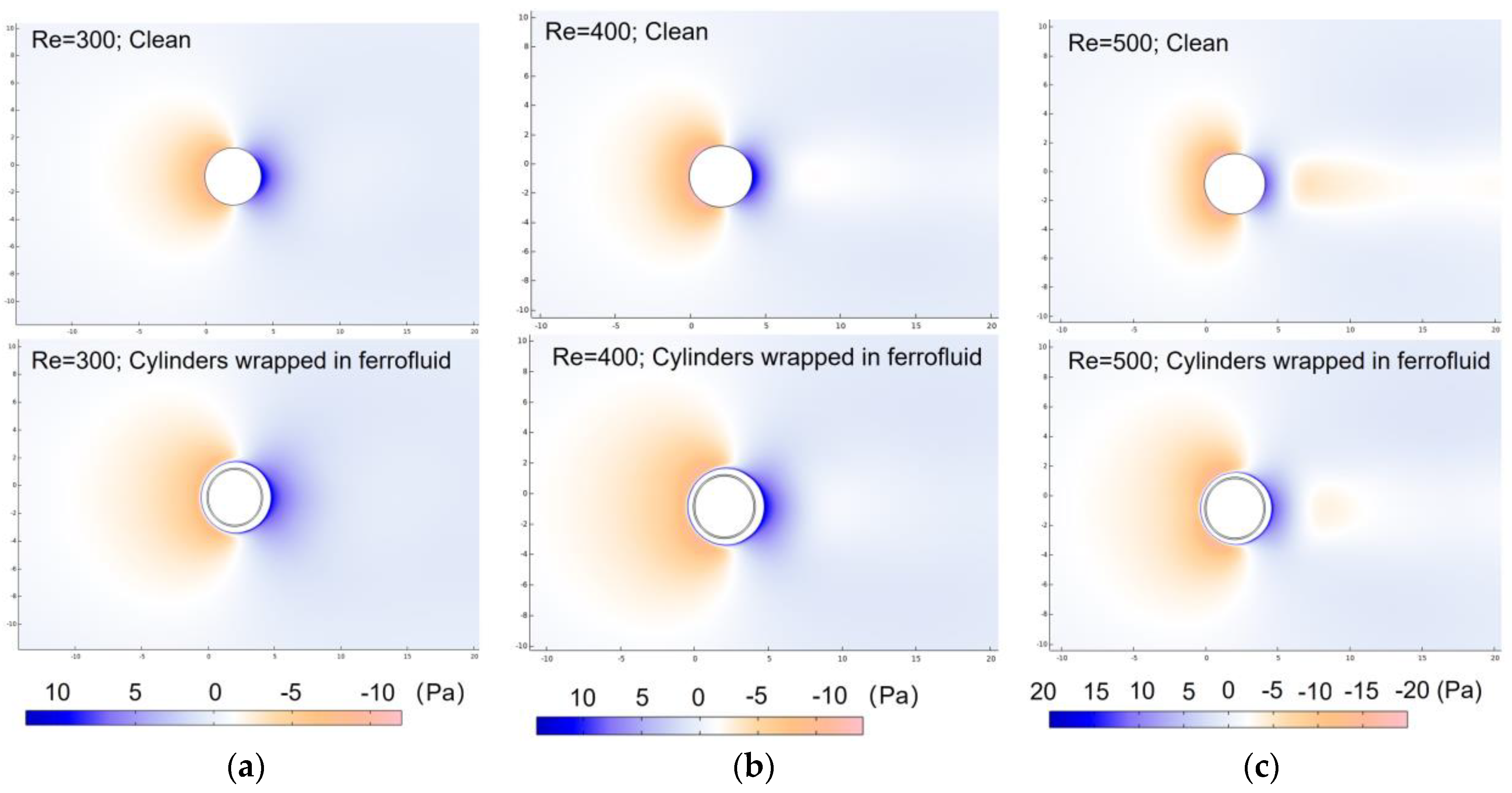
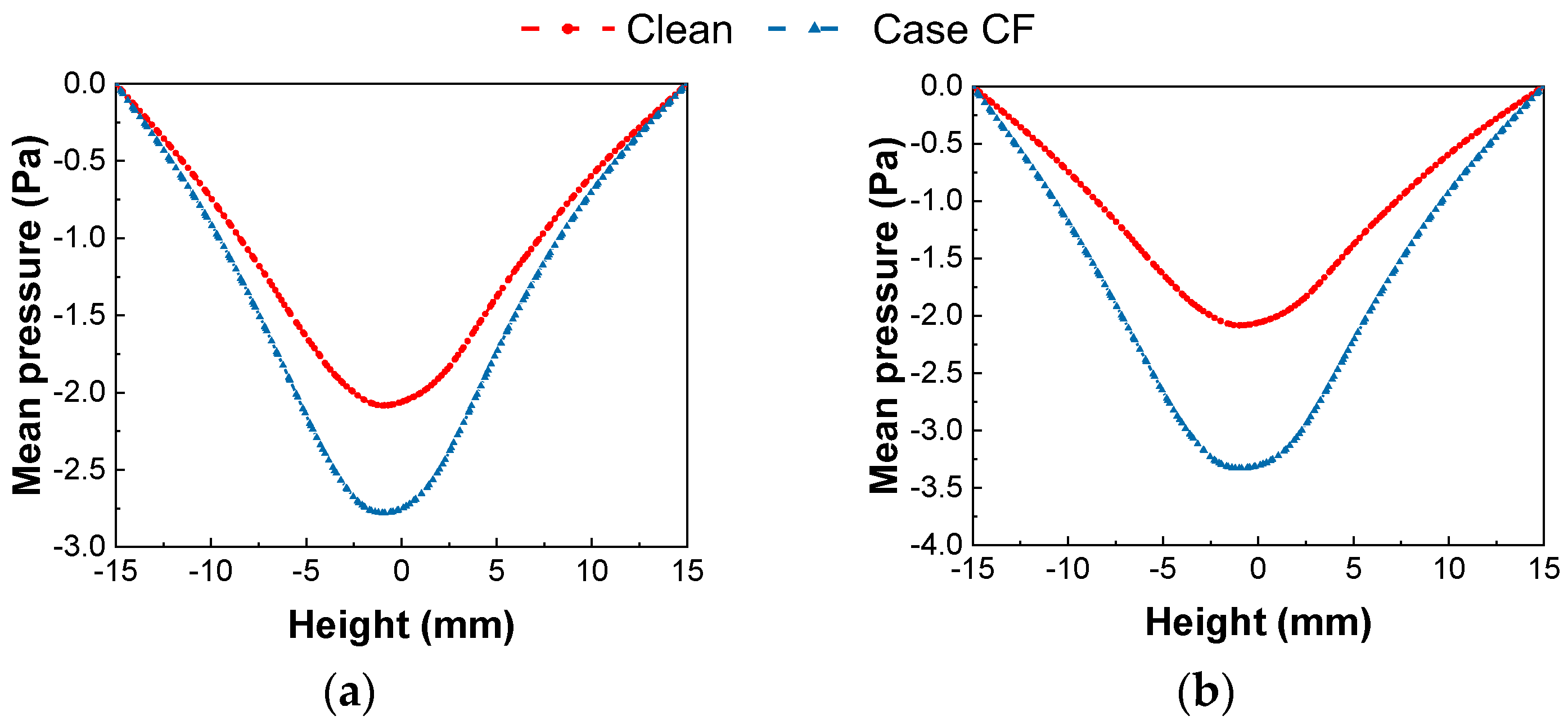
3.3. Pressure Distribution

Figure 15 illustrates the effect of ferrofluid film on the pressure distribution of the flow filed under different Re values. Similar to the mean velocity, the time-averaged pressure field p ¯ is calculated by p ¯ = 0 T p d t / T , with p the pressure at each point. It can be observed that the mean pressure on the windward and leeward sides of the cylinder are reversed and that in some areas of the wake, the mean pressure is opposite to the mean pressure on the leeward side. This inversion becomes more pronounced as Re increases. In the case of a cylinder wrapped with ferrofluid, a widening range of color changes can be observed compared with the clean case on both the windward and leeward sides, suggesting that the pressure gradient decreases. To quantify the ferrofluid film effects on the pressure distribution, the mean pressure rates on two vertical lines on the windward and leeward sides are given in Figure 16 under different Re values. As can be seen, on the windward side, the depression of the pressure line in the case of the ferrofluid-wrapped cylinder is significantly deeper than that in the clean case, and the mitigating effect becomes more pronounced as Re increases. An opposite situation occurs on the leeward side, where the fluctuation of the pressure line in the case of the ferrofluid-wrapped cylinder is significantly lower than that in the clean case. The fluctuation of the leeward side pressure plateau is significantly slowed down under the control of the ferrofluid-wrapped cylinder, which suppresses the generation and fluctuation of lift. Figure 17 further demonstrates the parametric effect of ferrofluidic films on the mean pressure distribution on both the windward and leeward sides. It indicates that all ferrofluid films of different viscosities change the distribution of pressure on the windward side. Moreover, ferrofluids of different viscosities all slow down the pressure fluctuations on the leeward side, and unlike the windward side, this slowing effect becomes more pronounced as the viscosity of the ferrofluid film decreases. Based on the control effect of ferrofluid films with different viscosities, we suggest that low-viscosity ferrofluid films are more beneficial in slowing down the main frequency of the lift coefficient, as demonstrated above.

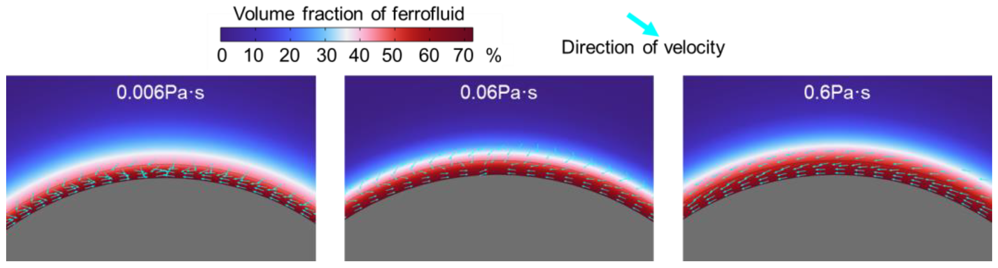
3.4. Flow Motion inside the Ferrofluid

Finally, to understand the ferrofluid film effect obtained above, we illustrate the flow motion inside the ferrofluid film. Here, the case of a ferrofluid with μ = 0.06 Pa·s and Δ = 0.10 mm and Re = 500 is selected as an example. Figure 18 and Figure 19 show the flow evolution at different stages. Generally, the flow motion inside the ferrofluid film can be divided into three stages. At first, a closed recirculation loop is formed. Meanwhile, the surface of the ferrofluid becomes fluctuating. The change in the direction of the velocity inside the ferrofluid film may be related to the increase in wall slip, as this change is more pronounced as the viscosity decreases (as shown in Figure 19). This induces wall slip. Then, with the flow of water, the velocity direction of the outer surface of the ferrofluid remains essentially the same as that of water, while the internal velocity direction forms a closed loop. During the third stage, vortices are generated, causing periodic fluctuations in the velocity direction of the ferrofluid due to the vortex shedding. The period of fluctuation in the velocity direction is approximately the same for the three viscous ferrofluids, and no linear relationship is found. The streamline in the upper and lower parts of the closed loop exhibits approximate symmetry. Therefore, it can be inferred that the magnetic liquid creates a recirculation area where it comes into horizontal contact with the water flow, as confirmed by Stancanelli [26,33]. The detailed flow motion inside the ferrofluid film is shown on the right of Figure 20. It can be observed that the surface of the magnetic liquid fluctuates. In combination with the aforementioned slip, it can be assumed that the flow field generates a drag-reduction effect at this interface.

4. Conclusions and Outlook

In summary, this article introduces a method of applying ferrofluid films for the control of flow separation in the external flow field. Numerical simulations were carried out to investigate the control performance of ferrofluid films as well as their parametric effects. The main conclusions are as follows:
(1) Ferrofluid films can prevent flow separation and stabilize the flow field in the wake. The cylinders wrapped with ferrofluid film have a larger vortex area and delay the first vortex shedding time. The maximum attenuation of the lift coefficient’s dominant frequency is up to over 45%.
(2) A lower viscosity ferrofluid film has a more pronounced effect in reducing the frequency of lift coefficient, the frequency of vortex shedding in the flow field, and wall slip. In addition, a thicker ferrofluid film has a more pronounced effect in reducing the frequency of vortex shedding, enlarging the wake region, and decreasing the mean velocity of the wake flow.
(3) The control effect of ferrofluid film is primarily due to wall slip and surface fluctuations. Wall slip increases the width and length of the wake and makes the flow field more stable. The surface fluctuations of the ferrofluid film appear to suppress the interaction of the upper and lower lift forces, thus reducing the frequency of vortex shedding. Furthermore, a recirculation region with an approximate mean velocity of 0 is formed within the ferrofluidic film. The flow angle at the outer surface of this region is positively correlated with wall slip.
In fact, through our research and that of related researchers, we found that ferrofluid films have a very high potential for application in the field of flow control and drag reduction. However, it is undeniable that ferrofluid films are still a long way from practical application, and the stability at high flow rates and the homogeneity of the ferrofluid films are the key problems that need to be solved urgently. In addition, the specific relationship between the internal motion of the ferrofluid films and the flow separation control will be further explored in the future.

Author Contributions

Conceptualization, H.Z.; methodology, C.W.; software, C.W.; validation, C.W., H.X. and Z.L.; formal analysis, C.W., H.X. and Z.L.; investigation, C.W. and H.X.; resources, C.W. and H.Z.; data curation, C.W.; writing—original draft preparation, C.W., H.X. and Z.L.; writing—review and editing, C.W., X.L., X.Z. and H.Z.; visualization, C.W., H.X. and Z.L.; supervision, X.L., X.Z. and H.Z.; project administration, X.L., X.Z. and H.Z.; funding acquisition, X.L. and H.Z. All authors have read and agreed to the published version of the manuscript.

Funding

This work was supported by the National Natural Science Foundation of China (52176160, 51976238, 12202308).

Data Availability Statement

The data that were used are confidential. The original contributions presented in the study are included in the article, further inquiries can be directed to the corresponding authors.

Acknowledgments

L. Yao is acknowledged for his instrumental role in the construction of the initial numerical simulation model.

Conflicts of Interest

The authors declare that they have no known competing financial interests or personal relationships that could have appeared to influence the work reported in this paper.

References

  1. Chen, W.-L.; Huang, Y.; Chen, C.; Yu, H.; Gao, D. Review of active control of circular cylinder flow. Ocean Eng. 2022, 258, 111840. [Google Scholar] [CrossRef]
  2. Jiang, H.; Cheng, L. Flow separation around a square cylinder at low to moderate Reynolds numbers. Phys. Fluids 2020, 32, 044103. [Google Scholar] [CrossRef]
  3. Heil, M.; Rosso, J.; Hazel, A.L.; Brøns, M. Topological fluid mechanics of the formation of the Kármán-vortex street. J. Fluid Mech. 2017, 812, 199–221. [Google Scholar] [CrossRef]
  4. Sohankar, A.; Norberg, C.; Davidson, L. Simulation of three-dimensional flow around a square cylinder at moderate Reynolds numbers. Phys. Fluids 1999, 11, 288–360. [Google Scholar] [CrossRef]
  5. Choi, H. Control of flow over a bluff body. In Fifth International Symposium on Turbulence and Shear Flow Phenomena; Begel House Inc.: Danbury, CT, USA, 2007. [Google Scholar] [CrossRef]
  6. Lee, S.J.; Lim, H.C.; Han, M.; Lee, S.S. Flow control of circular cylinder with a V-grooved micro-riblet film. Fluid Dyn. Res. 2005, 37, 246. [Google Scholar] [CrossRef]
  7. Lim, H.C.; Lee, S.J. Flow control of circular cylinders with longitudinal grooved surfaces. AIAA J. 2002, 40, 2027–2036. [Google Scholar] [CrossRef]
  8. Huang, S. VIV suppression of a two-degree-of-freedom circular cylinder and drag reduction of a fixed circular cylinder by the use of helical grooves. J. Fluids Struct. 2011, 27, 1124–1133. [Google Scholar] [CrossRef]
  9. Wang, L.; Liu, X. Aeroacoustic investigation of asymmetric oblique trailing-edge serrations enlighted by owl wings. Phys. Fluids 2022, 34, 015113. [Google Scholar] [CrossRef]
  10. Gao, D.; Huang, Y.; Chen, W.L.; Chen, G.; Li, H. Control of circular cylinder flow via bilateral splitter plates. Phys. Fluids 2019, 31, 057105. [Google Scholar] [CrossRef]
  11. Deng, Z.; Chen, W.L.; Yang, Z.F. The control mechanism of the soft trailing fringe on the flow characteristics over an airfoil. Phys. Fluids 2022, 34, 95112. [Google Scholar] [CrossRef]
  12. Brücker, C. Interaction of flexible surface hairs with near-wall turbulence. J. Phys. Condens. Matter 2011, 23, 184120. [Google Scholar] [CrossRef] [PubMed]
  13. Hasegawa, M.; Sakaue, H. Microfibers coating for drag reduction by flocking technology. Coatings 2018, 8, 464. [Google Scholar] [CrossRef]
  14. Lin, L.; Deng, Z.; Chen, W.; Li, H.; Gao, D. Flow control of a circular cylinder by self-adaptive furry microfibers. Phys. Fluids 2022, 34, 105128. [Google Scholar] [CrossRef]
  15. Bashtovoi, V.G.; Krakov, M.S.; Taits, E.M. Intensification of heat transfer and reduction of the resistance under conditions of flow in channels with a magnetic-fluid coating. 1. Planar coating. J. Eng. Phys. 1990, 58, 435–439. [Google Scholar] [CrossRef]
  16. Krakov, M.S. Experiments involving a cylindrical magnet coated with a magnetic fluid in a transverse flow. Magnetohydrodynamics 1989, 1, 61–64. [Google Scholar]
  17. Jin, X.; Dai, M.; Zou, X.; Laima, S. Suppression of flow separation around a finite wall-mounted square cylinder by suction at the side leading edge. Phys. Fluids 2024, 36, 017120. [Google Scholar] [CrossRef]
  18. Lam, K.M. Vortex shedding flow behind a slowly rotating circular cylinder. J. Fluids Struct. 2009, 25, 245–262. [Google Scholar] [CrossRef]
  19. Toms, B.A. Observation on the flow of linear polymer solutions through straight tubes at large Reynolds numbers. Proc. Int. Rheol. Congr. 1948, 2, 131–141. [Google Scholar]
  20. Li, F.; Bo, Y.; Wei, J.; Kawaguchi, Y. Surfactant Turbulence Reduction; Higher Education Publishing House: Beijing, China, 2012; p. 220. ISBN 9787040343151. [Google Scholar]
  21. Solomon, B.R.; Khalil, K.S.; Varanasi, K.K. Correction to Drag Reduction using Lubricant-Impregnated Surfaces in Viscous Laminar Flow. Langmuir 2016, 32, 8287. [Google Scholar] [CrossRef]
  22. Deutsch, S.; Castano, J. Microbubble skin friction reduction on an axisymmetric body. Phys. Fluids 1986, 29, 3590–3596. [Google Scholar] [CrossRef]
  23. Madavan, N.K.; Detusch, S.; Merkle, C.L. Measurements of local skin friction in a microbubble–modified turbulent boundary layer. Fluid. Mech. 1985, 156, 37–256. [Google Scholar] [CrossRef]
  24. Krakov, M.S. Flow separation control by means of magnetic fluid. Izv. Akad. Nauk. SSSR Mekh. Zhidk. Gaza 1984, 39, 119–122. [Google Scholar] [CrossRef]
  25. Krakov, M.S.; Kamiyama, S. Steady flow past a circular cylinder coated with magnetic fluid: Flow structure, drag reduction and coating deformation. J. Fluid Mech. 1995, 295, 1–22. [Google Scholar] [CrossRef]
  26. Stancanelli, L.M.; Secchi, E.; Holzner, M. Magnetic fluid film enables almost complete drag reduction across laminar and turbulent flow regimes. Commun. Phys. 2024, 7, 30. [Google Scholar] [CrossRef]
  27. Krakov, M.S.; Maskalik, E.S.; Medvedev, V.F. Hydrodynamic resistance of pipelines with a magnetic fluid coating. Fluid Dynam. 1989, 24, 715–720. [Google Scholar] [CrossRef]
  28. Outokesh, M.; Amiri, H.A.; Miansari, M. Numerical insights into magnetic particle enrichment and separation in an integrated droplet microfluidic system. Chem. Eng. Process.-Process Intensif. 2022, 170, 108696. [Google Scholar] [CrossRef]
  29. Olsson, E.; Kreiss, G. A conservative level set method for two phase flow. J. Comput. Phys. 2005, 210, 225–246. [Google Scholar] [CrossRef]
  30. Kholardi, M.D.; Farhadi, M. Understanding droplet formation in T-shaped channels with magnetic field influence: A computational investigation. Phys. Fluids 2024, 36, 053302. [Google Scholar] [CrossRef]
  31. Ganguly, R.; Sen, S.; Puri, I.K. Thermomagnetic convection in a square enclosure using a line dipole. Phys. Fluids 2004, 16, 2228–2236. [Google Scholar] [CrossRef]
  32. Norberg, C. Fluctuating lift on a circular cylinder: Review and new measurements. J. Fluids Struct. 2003, 17, 57–96. [Google Scholar] [CrossRef]
  33. Dunne, P.; Adachi, T.; Dev, A.A.; Sorrenti, A.; Giacchetti, L.; Bonnin, A.; Bourdon, C.; Mangin, P.H.; Coey, J.M.D.; Doudin, B.; et al. Liquid flow and control without solid walls. Nature 2020, 581, 58–62. [Google Scholar] [CrossRef]
Figure 1. Schematic of the flow configuration.
Inventions 09 00065 g001
Figure 2. The distribution of the magnetic field for the cylinder magnetic strength at 250 mT.
Inventions 09 00065 g002
Figure 3. The process of vortex shedding for the case of the clean cylinder at Re = 500.
Inventions 09 00065 g003
Figure 4. The process of vortex shedding for the case of the ferrofluid−wrapped cylinder at Re = 500, where μ = 0.06 Pa·s and Δ = 0.1 mm, respectively.
Inventions 09 00065 g004
Figure 5. The effects of cylinder thickness on flow field at Re = 500: (a) t = 0.48 s, (b) t = 0.68 s.
Inventions 09 00065 g005
Figure 6. Comparisons of the energy spectrum in the frequency domain of the velocity at different locations and flow conditions: (a) (2, 4), (b) (12, 4), (c) (22, 4), (d) (32, 4), (e) (32, 0), (f) (32, −4).
Inventions 09 00065 g006
Figure 7. Comparison of clean case and ferrofluid-wrapped case with μ = 0.06 Pa·s and Δ = 0.10 mm different Re at the location of (32, 0): (a) Re = 300, (b) Re = 400, (c) Re = 500.
Inventions 09 00065 g007
Figure 8. Thickness effect of the ferrofluid film on the energy spectrum of the velocity at Re = 500 with μ = 0.06 Pa·s: (a) Δ = 0.05 mm, (b) Δ = 0.10 mm, (c) Δ = 0.15 mm.
Inventions 09 00065 g008
Figure 9. Viscosity effect of ferrofluid film with Δ = 0.1 mm on the dominant frequency of lift coefficient at different Re.
Inventions 09 00065 g009
Figure 10. Comparison of the mean velocity distribution between the clean case and the ferrofluid−wrapped case with μ = 0.06 Pa·s and Δ = 0.10 mm at Re = 300.
Inventions 09 00065 g010
Figure 11. Ferrofluid viscosity and thickness effect on the mean velocity distribution under different situations: (a) Re = 300; (b) Re = 400; (c) Re = 500.
Inventions 09 00065 g011
Figure 12. The effects of ferrofluid viscosity and thickness on the wake length under different situations: (a) Viscosity effect, (b) Thickness effect.
Inventions 09 00065 g012
Figure 13. Slip phenomena on ferrofluid surfaces with different Re: (a) Re = 300, (b) Re = 400, (c) Re = 500.
Inventions 09 00065 g013
Figure 14. Slip phenomena on ferrofluid surfaces with different viscosities.
Inventions 09 00065 g014
Figure 15. Comparison of pressure distribution between the clean case and the ferrofluid-wrapped case with μ = 0.06 Pa·s and Δ = 0.10 mm: (a) Re = 300, (b) Re = 400, (c) Re = 500.
Inventions 09 00065 g015
Figure 16. Comparison of pressure distribution between the clean case and the ferrofluid-wrapped case with μ = 0.06 Pa·s and Δ = 0.10 mm along Line 2 ((a) Re = 300, (b) Re = 400, and (c) Re = 500) and along Line 3 ((d) Re = 300, (e) Re = 400, and (f) Re = 500).
Inventions 09 00065 g016aInventions 09 00065 g016b
Figure 17. Ferrofluid viscosity effect on the mean velocity distribution under different situations on the windward and leeward sides: (a) Line 2 and (b) Line 3.
Inventions 09 00065 g017
Figure 18. The flow behavior inside the ferrofluid film at different stages: (a) the stage without vortex shedding, (b) when vortex shedding begins to occur.
Inventions 09 00065 g018
Figure 19. Flow behaviors of ferrofluids with different viscosities at t = 0.132 s.
Inventions 09 00065 g019
Figure 20. The flow motion inside the ferrofluid film with μ = 0.06 Pa·s and Δ = 0.10 mm at Re = 500: (a) the instantaneous flow motion at t = 0.783 s, (b) the mean flow motion.
Inventions 09 00065 g020
Table 1. Material properties.
Materialρ (kg/m3)μ (Pa·s)Δ (mm)
Water10000.001/
Ferrofluid12000.006, 0.06, 0.60.05, 0.1, 0.15
Table 2. Flow conditions.
u (m/s)Re
0.075300
0.1400
0.125500
Table 3. The comparison of the St number between numerical simulation and empirical function.
Re = 300StError
Numerical simulation0.20000.79%
Empirical function0.2016 [32]
Disclaimer/Publisher’s Note: The statements, opinions and data contained in all publications are solely those of the individual author(s) and contributor(s) and not of MDPI and/or the editor(s). MDPI and/or the editor(s) disclaim responsibility for any injury to people or property resulting from any ideas, methods, instructions or products referred to in the content.

