1. Introduction
Since its appearance, the automobile has become more and more a main necessity for human beings, which allows them to make life easier and minimize travel time. However, in recent years the automobile sector has posed certain problems, such as gas emissions, the greenhouse effect, dependence on oil, which continues to become scarce, etc. These circumstances impose an orientation towards new technologies to overcome these problems [
1]. In the upcoming years, electric vehicles (EVs) powered by renewable energies, can play a significant role in the transition to sustainable modes of transportation, reduce CO
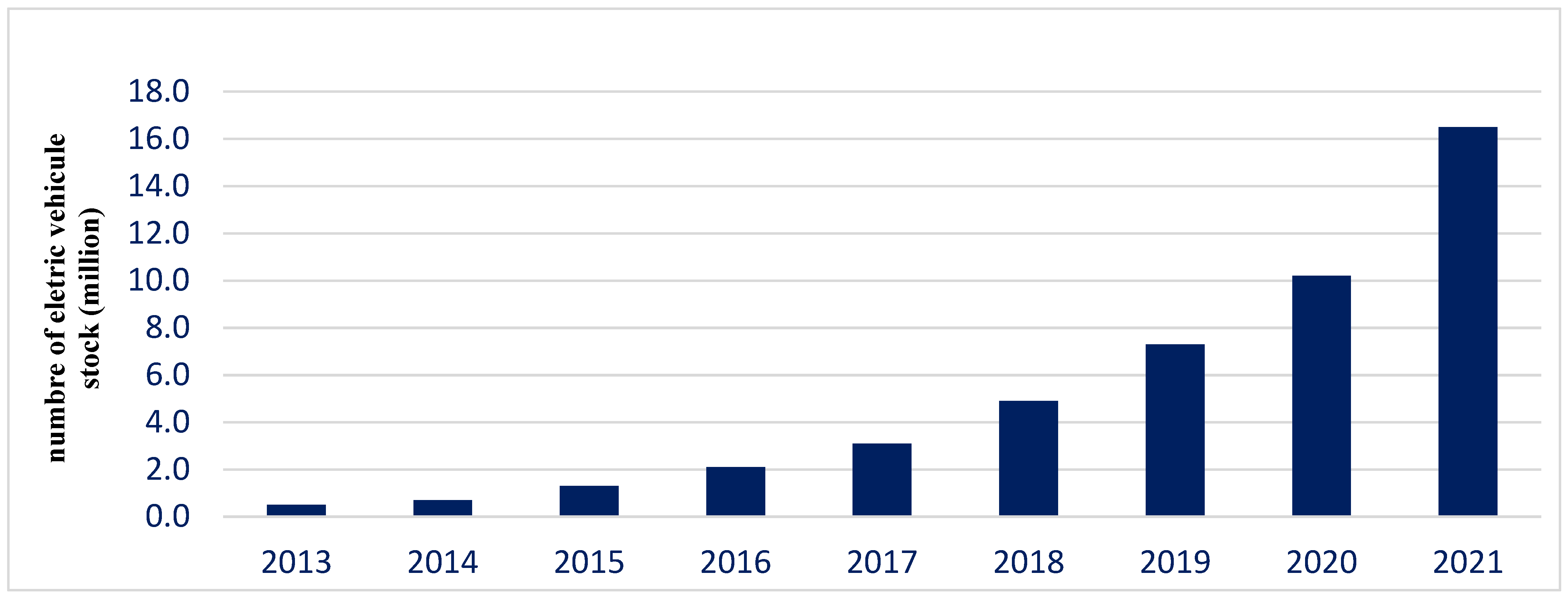
2 emissions, and improve local air quality. Currently, the rate of EV development is exponentially increasing, more than 16.5 million electric automobiles were in circulation in 2021, a tripling in only three years as shown in
Figure 1 [
2]. The main forces behind the recent global growth of EVs are the tightening of CO
2 emission limits that took place in 2020 and 2021, as well as the increase in the price of fuel. The pace of sales was also aided by the increase in tax breaks and the increase in purchase subsidies [
2].
The rapid development of EVs has led to a sharp increase in the demand for electricity from these electric vehicles, which has led to thinking about a set of solutions to remedy this increase in energy demand. Several research directions are addressed on this topic, such as the integration of EV in micro-grids [
3,
4], the Vehicle-to-Grid (V2G) and Vehicle-to-Vehicle (V2V) concepts [
5,
6,
7,
8,
9], charging management of EVs in parking lots [
10,
11], the impact of EV on the grid [
12,
13], the charging infrastructure [
14], battery degradation [
15] and the charging economics concept [
16]. The integration of EVs in residential systems is an important aspect of addressing the problem of high energy demand, with the optimal integration of renewable energy systems (RES) and energy storage systems (ESS). This integration makes it possible to exploit the maximum power of renewable energy sources, as well as to use the EV as a temporary storage system in the house and as a source of energy production in order to decrease the budget of EV operation and home consumption, and to relieve the public electricity grid.
Most EVs are used for a short time around 5% of the day, and for the rest of the day around 95% of the remaining time [
17], EVs are parked in workplace parking lots or at home. Thus, we can benefit from them during those times when they are parked. The EV can use its battery to store energy from renewable energy sources or to help storage systems to store that energy; in this case, the vehicle is used as a storage system. During low energy production, the EV can intervene to help meet the requirements of home loads by sending the missing energy, this is the Vehicle-to-Home (V2H) concept. During on-peak periods when the price of electricity from the public grid is particularly high, the EV can be used as a source of energy, and it has the ability to sell the energy stored in its battery to the electrical grid; this is the V2G concept. To manage these operating modes, plan the charging of the EV and manage the energy exchange in the residential system between the sources and the loads, the EMS make it possible to meet these requirements. Charging is said to be “normal” when the car charges to full capacity as soon as it is connected to the grid. The EMS makes it possible to modify this “normal” behavior, with the use of different operating modes such as V2H, and V2G to minimize the cost of the owner’s electricity bill while meeting his personal constraints in terms of the EV’s availability and autonomy.
This work presents a residential system connected to the electrical grid. It consists of PV as the primary source, a battery system for energy storage, an EV, and residential loads. A hybrid control has been suggested in this article to control system components. The charge and discharge of the EV are managed by the combined PI-Fuzzy logic control, which combines the advantages of both conventional PI controls and fuzzy logic. The injection and the use of the grid are controlled by the Active Disturbance Rejection Control (ADRC). The energy management in this residential system is carried out using the rule-based method. The electrical grid is used as a backup source, and the PV is the main source that must be exploited to the maximum. In the case when the energy generated through the PV system reached its maximum, it provides the power to the residential loads and charges the batteries and the electrical vehicle battery, and the excess PV power is fed to the grid. Additionally, when the PV system’s power output is low, the battery and the EV are used to supply residential loads. The grid maintains the shortage when the power of the components of the system is insufficient to meet the loads. Several scenarios are studied in this work, taking into account certain conditions such as energy generated through the PV generator, the demand for residential loads, the availability of the EV, EV SOC.
The main contributions of this paper include:
A hybrid control system that includes PI-Fuzzy logic, and ADRC.
A combined PI-Fuzzy logic control, which combines the benefits of a classical PI controller and a fuzzy logic controller.
An energy management system that addresses all possible scenarios, considering the emergency use of the EV by the owner.
The use of the V2H concept to relieve the electricity grid.
The outline of this article is as follows:
Section 2 displays a description of the residential system. The presentation of the proposed control laws and the energy management system are provided in
Section 3.
Section 4 shows the simulation results and a discussion of the main scenarios and operation modes. Finally,
Section 5 provides conclusions.
Motivation and Novelty
This paper proposes a hybrid control model and energy management strategy that examines possible scenarios, for energy exchange in a residential system including PV system, EV, and energy storage system, residential loads and electricity grid. The proposed EMS makes it possible to exploit the maximum power of PV system. It is primarily used as the main source, and the grid as a backup source. Furthermore, the V2H and H2V concepts have been taken into account. Compared with the existed articles, this paper combines and provides a complete description of all possible operational scenarios with or without an EV connection, to relieve the power grid, considering the emergency use of the EV by the owner.
2. System Description
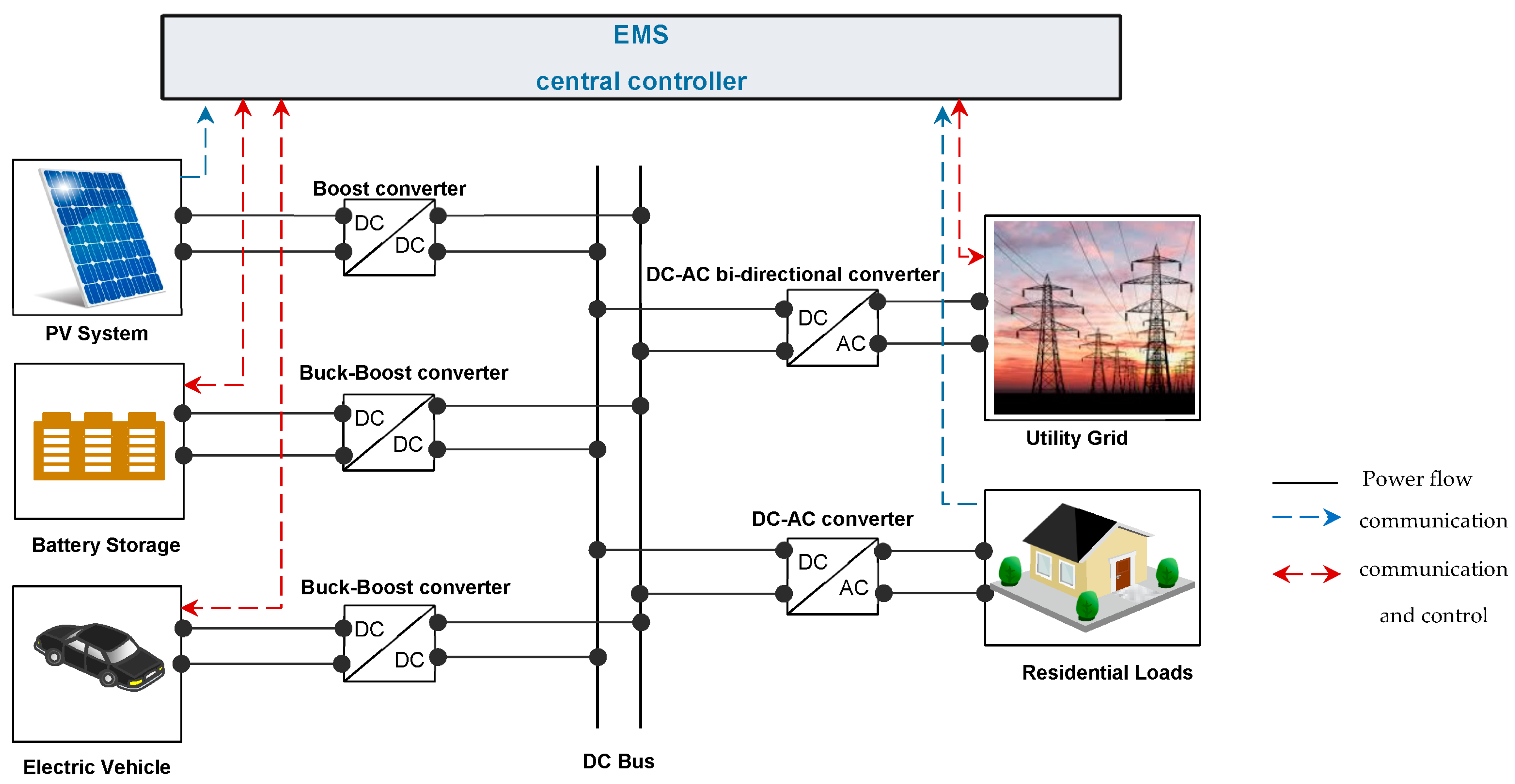
The proposed residential system consists of a PV system with battery storage system, EV, residential loads, and utility grid as shown by
Figure 2. The PV system is considered as the main source of energy, the battery system acts as a method for momentary storage. Whereas the EV is used as a load in the context of the H2V concept, or energy source distributed as part of the possibility of income from V2H. Finally, the main grid is used as a backup source.
At this home, the energy control system that is in charge of managing the energy flow in the home communicates with the various elements that compose our residential system, the load and all energy sources. This is in order to know at any time the state of each element and information on the energy produced by the PV system, the energy consumption, the availability of the EV, etc.
Figure 2 presents the configuration of the residential system model proposed in this work. The PV system is connected to the DC bus using the Boost converter, that achieves the MPPT control. Additionally, the EV is coupled to the DC bus by the bi-directional Buck-Boost converter, which carries out the charging and discharging control of the EV. In H2V mode, the EV operates in charging mode (EV used as consumer). In V2H mode, the EV operates in discharging mode (EV used as power source). Likewise, the storage battery is coupled to the DC Bus by the Buck-Boost converter, which performs the charge and discharge control of the battery. On the other side, the electrical grid is coupled to the DC Bus using the bi-directional DC-AC converter. This converter can be operated as an inverter, in the case of energy fed to the power grid. Or as a rectifier to supply the load, in order to meet residential load requirements. Similarly, the residential loads are coupled to the DC bus by the DC-AC converter.
Residantial System Parameters
In this house, all the components composing this residential system namely the PV system, EV, battery storage, electrical grid and the residential loads are connected to the DC bus, which is set to 900 V.
The model of the PV system used can generate a maximum power of 63 kW at 25 °C and 1000 W/m
2. The EV used is of the Renault ZOE type with a battery capacity of 22 kWh [
18], the storage battery is of 50 Ah capacity [
19], as well as a residential load of 26 kW and a nominal voltage electrical grid of 220/380 V, 50 Hz are considered in this work.
Table 1 displays the characteristics of these components.
3. Control Strategy of the Proposed Residential System
The general structure of the overall control system of the proposed residential system is presented in
Figure 3. The control system detects the power produced by the PV, the power demanded by the residential loads, the availability of EV, the state of charge and the charging power of the storage battery and the EV, the voltage from the DC bus to generate the control signals for each power converter, in order to control how much energy is exchanged in the residential system between the loads and the sources.
3.1. Local Controllers Design
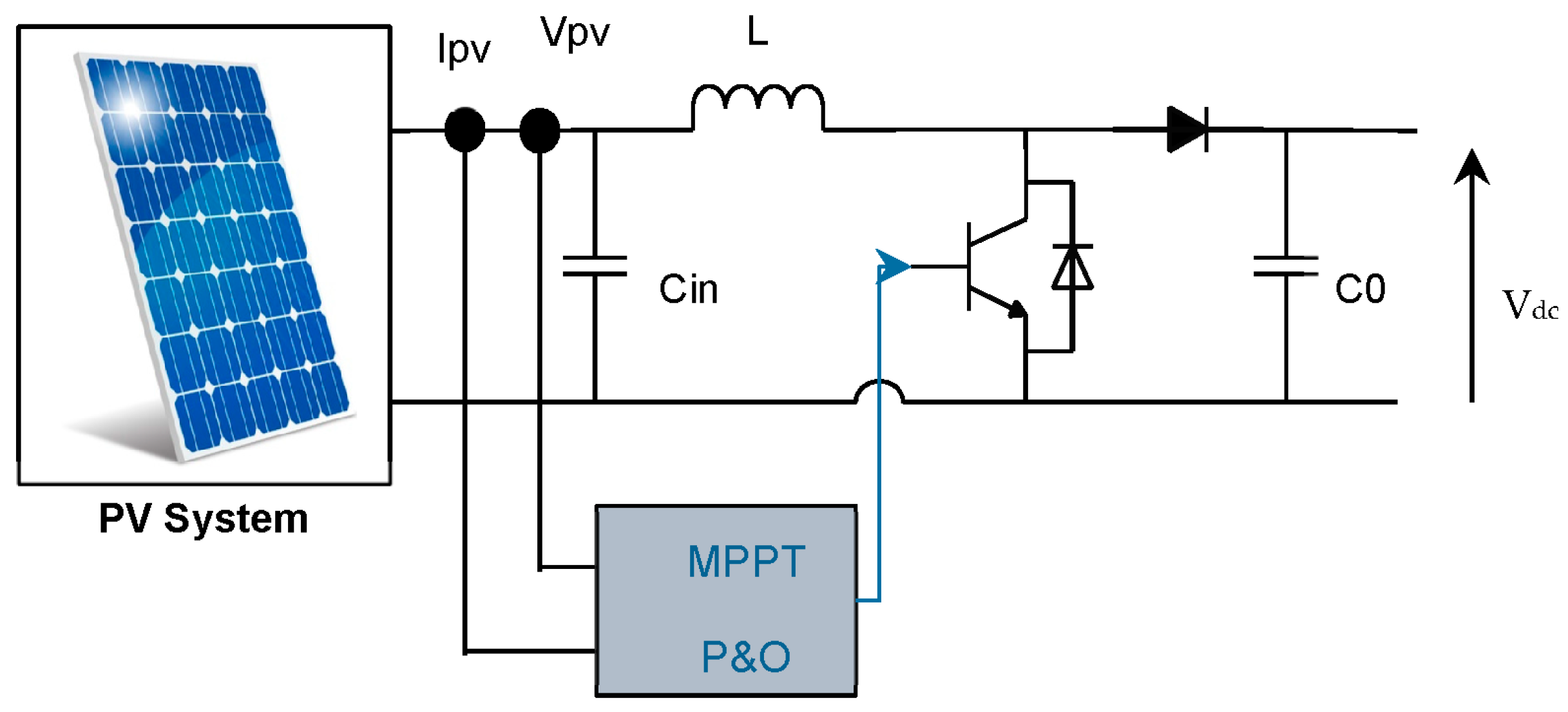
3.1.1. PV System Control
In order to maximize the power available in PV arrays, Maximum Power Point Tracking (MPPT) techniques based on the perturb and observe (P&O) algorithm are employed to maintain the operating point of the PV array at its maximum power point [
20,
21].
The goal of the technique is to maintain the PV output power close to the maximum power point (MPP). To achieve this, the resulting current and voltage values of the PV generator are recorded, then the power is determined. Subsequently, the variation of the power and the voltage are calculated to know the location of this point (),)) in the P–V curve and the sign of the derivatives are positive or negative, a positive power derivative means that the operating point is approaching the MPP. Then, the sign of the voltage drift is tested to know the direction of the search.
The search direction determines whether the control signals of pulse width modulation.
(PWM) is in the increase or decrease stage of the duty cycle.
3.1.2. EV Control
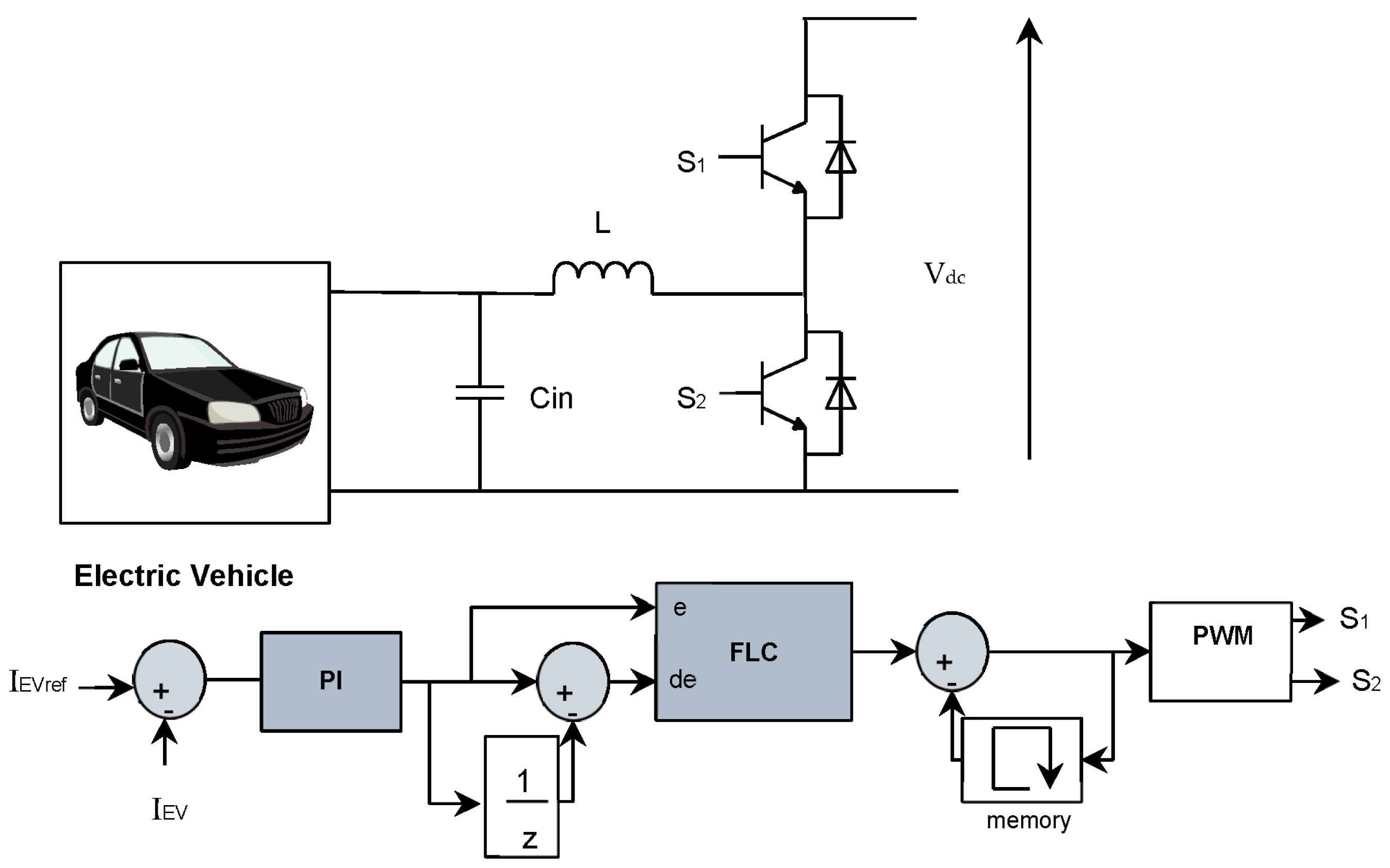
A bi-directional buck-boost converter is used between the EV and the DC bus to determine when the EV battery is charged and discharged [
22,
23].
Conventional PI controllers are widely used in most of the energy systems due to their simple design, easy implementation, affordable price and their robustness. However, for non-linear systems and in case of parameters variation PI control is not effective. On the other hand, the fuzzy logic control (FLC) is an effective control in case of system parameters variations, the uncertainty of the inputs, the non-linearity of the systems and it presents a reduced response time. Therefore, to control the converter we have developed a hybrid PI-Fuzzy logic control, that combines the benefits of traditional PI controller with the advantages of the fuzzy logic controller, in order to obtain a robust and flexible controller to effectively manage EV charging and discharging.
A PI-Fuzzy logic controller controls the EV charging and discharging using a reference current that is determined by the EMS based on the operating mode of EV as shown by
Figure 4. Similarly, a bidirectional buck/boost converter based a PI-Fuzzy logic controller is utilized to control charging and discharging of the battery energy storage, in the same way.
Table 2 provides the FLC rule base that was used in this research work.
The Membership functions for e and de applied in this work are:
NB: is Negative Big
NS: is Negative Small
ZZ: is Zero
PS: Positive Small
PB: is Positive Big.
The fuzzy rules used in this work are:
When E is PB and DE is NB ⇒ the output is ZZ
When E is PB and DE is NS ⇒ the output is PS
When E is PB and DE is ZZ ⇒ the output is PS
When E is PB and DE is PS ⇒ the output is PB
When E is PB and DE is PB ⇒ the output is PB
Where e and de are the inputs of the FLC, they respectively present the error and the change in error.
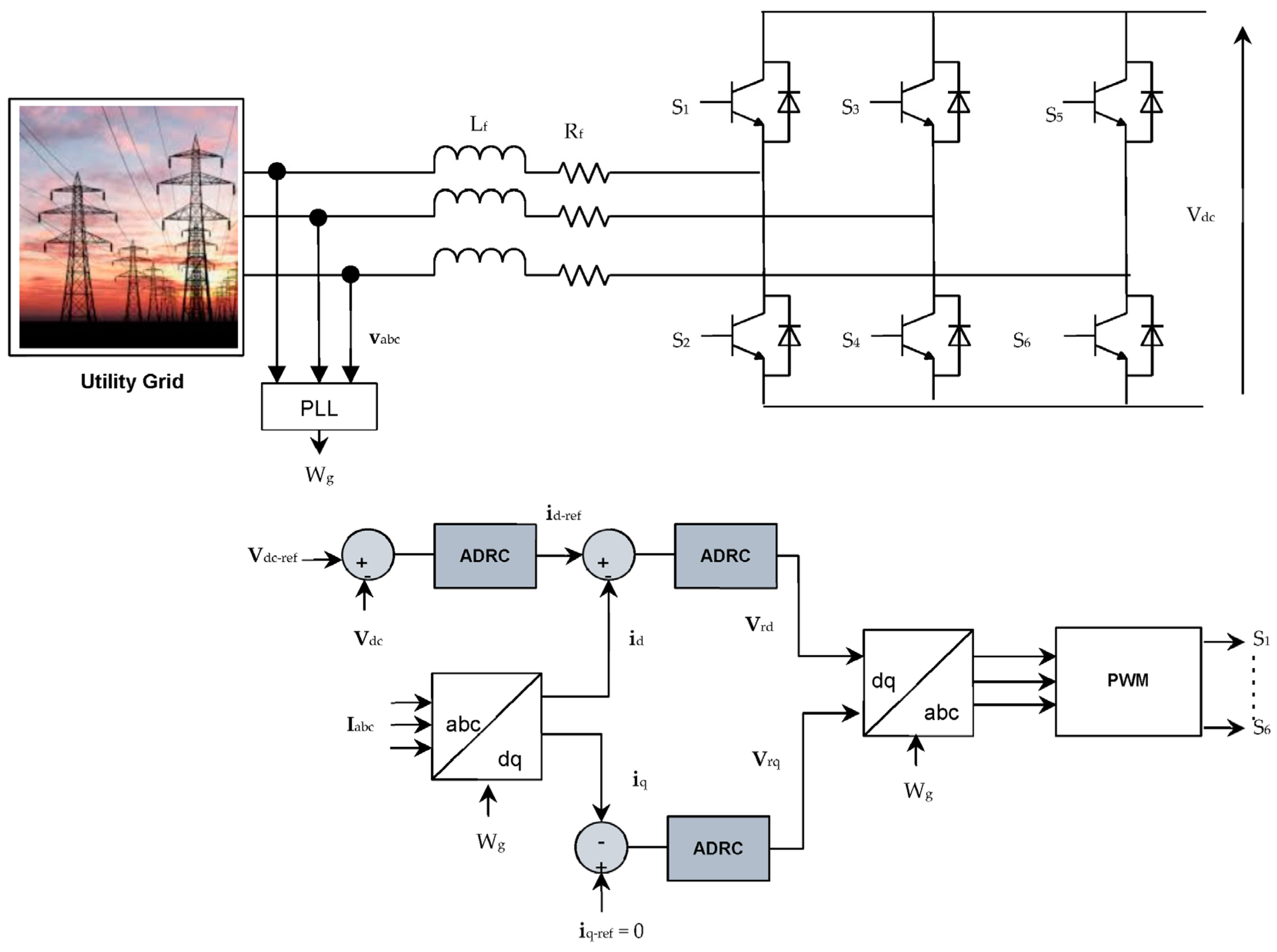
3.1.3. Grid-Side Converter Control
The grid-side converter is implemented using the bi-directional DC-AC converter located between the electrical grid and the DC bus. The control of this converter is based on ADRC control, which controls the flow of energy from or to the electrical grid as depicted by
Figure 5. This converter operates in two ways, either rectifier or inverter depending on the situations. When we want to use the power of the electrical grid, the converter is therefore operated as a rectifier, the current is flowing from the converter to the DC bus. Contrarywise, when we want to supply the excess power to the grid, the converter is therefore operated like an inverter, the current is flowing from the DC bus to the main grid [
25].
ADRC is a robust control method, it is employed in this work to control the grid currents and the DC bus voltage.
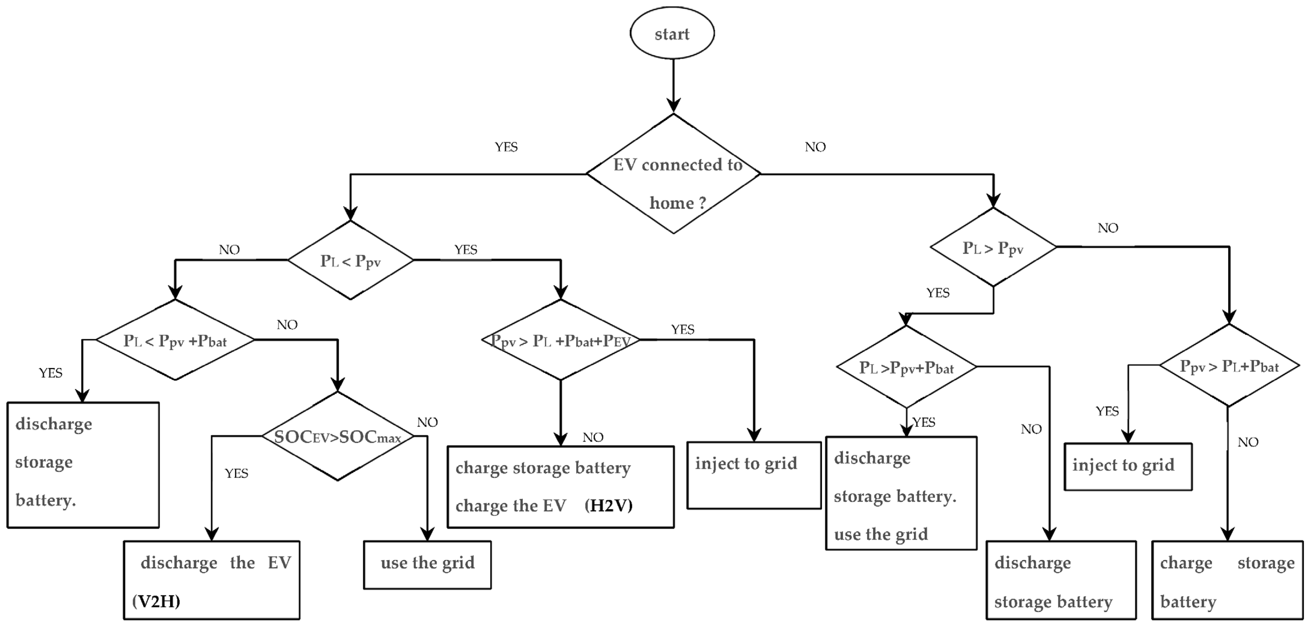
3.2. Rule-Based Energy Management System
To manage the energy between the demand and generation in residential system, the rule-based algorithm is used to implement an energy management system. All energy management parameters are provided in
Table 3.
The proposed rule-based algorithm makes it possible to plan the use of the components of the residential system according to the power produced, the power requested and the availability of EV. The electric vehicle has two operating cases. The first case when the EV is connected to the home, in this case the electric vehicle participates in the residential system and can operate in two modes. The H2V mode, in this mode the vehicle is considered as a load, it consumes energy. The V2H mode, in this mode the vehicle is considered as an energy source, it provides energy. The second case of operation is when the EV is not connected at home, in this case the electric vehicle does not participate in the residential system.
The PV system is used as a main source in this work and the electrical grid as a backup source. If the PV generator produces more energy, the energy from the PV is used to satisfy the residential loads demand, charge the home storage batteries and the EV battery (if connected) to be used when needed, and the excess PV energy is fed to the grid. Moreover, when the power generated by the PV generator is low, the storage battery and the EV are used to supply the residential loads, the power grid intervenes to ensure continuity of service if the power from the storage battery and the EV and the PV is not enough to satisfy the demand for residential loads.
The proposed control system consists of several possible scenarios following two cases:
Case 1: EV is connected to home
Case 2: EV is not connected to home
Figure 6 depicts the algorithmic flowchart of the proposed EMS describing different operating modes.
4. Simulation Results and Discussion
To verify the effectiveness of the proposed residential EMS and associated control strategies, all the derived sceanrios have been simulated and results presented and discussed. This is in order to get a thorough investiagation that allow to demonstrate the interest of renewables and V2H technology in the residential sector.
The EV can be operated in V2H mode only when it is available (connected to home) and when its charge level is higher than the SOCmax, which is set in this study at 50%, because the EV must always be available and charged with an acceptable state of charge as soon as the user needs it, it is necessary to think of the emergency case of use of the vehicle by the owner.
4.1. EV Connected to Home
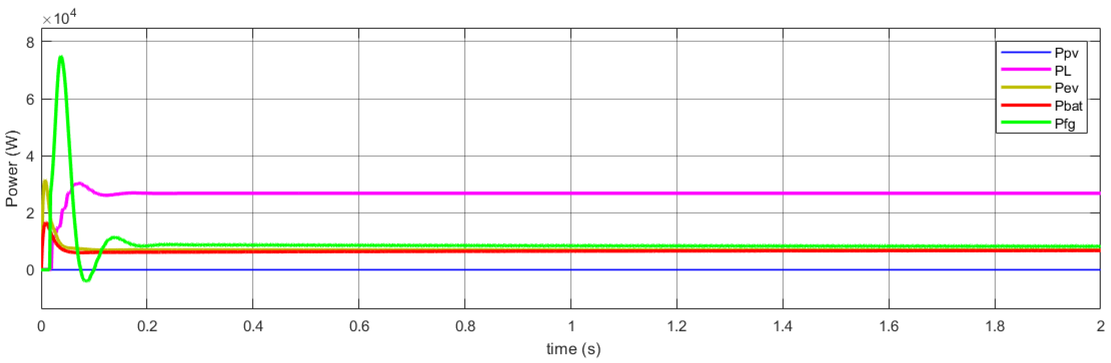
4.1.1. Case 1
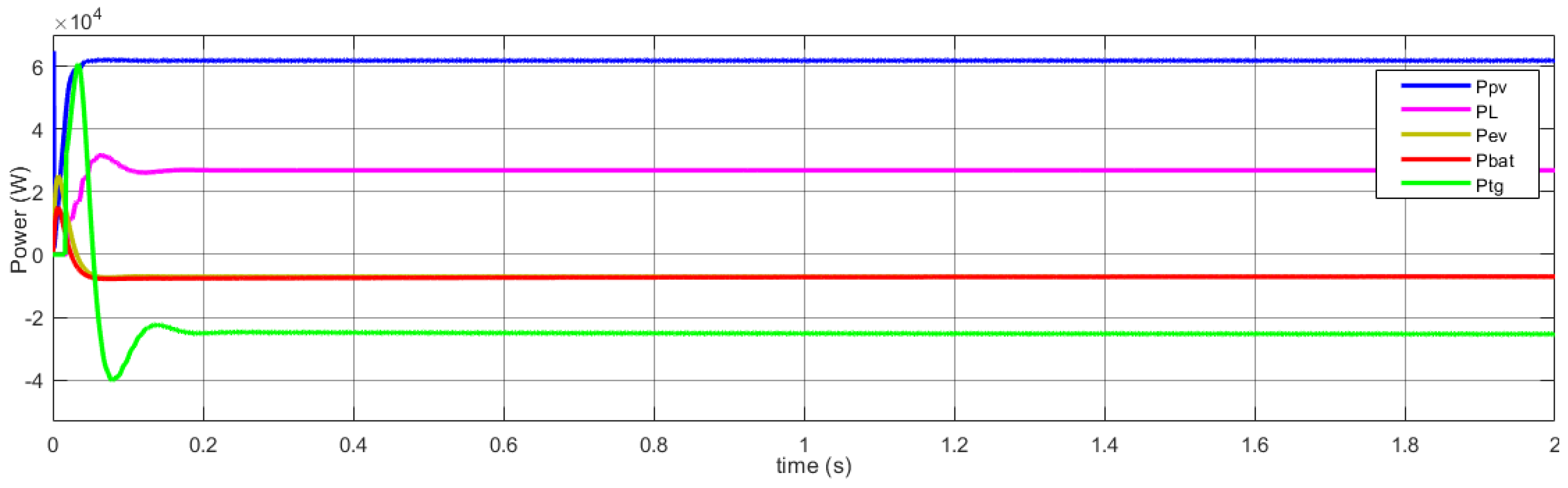
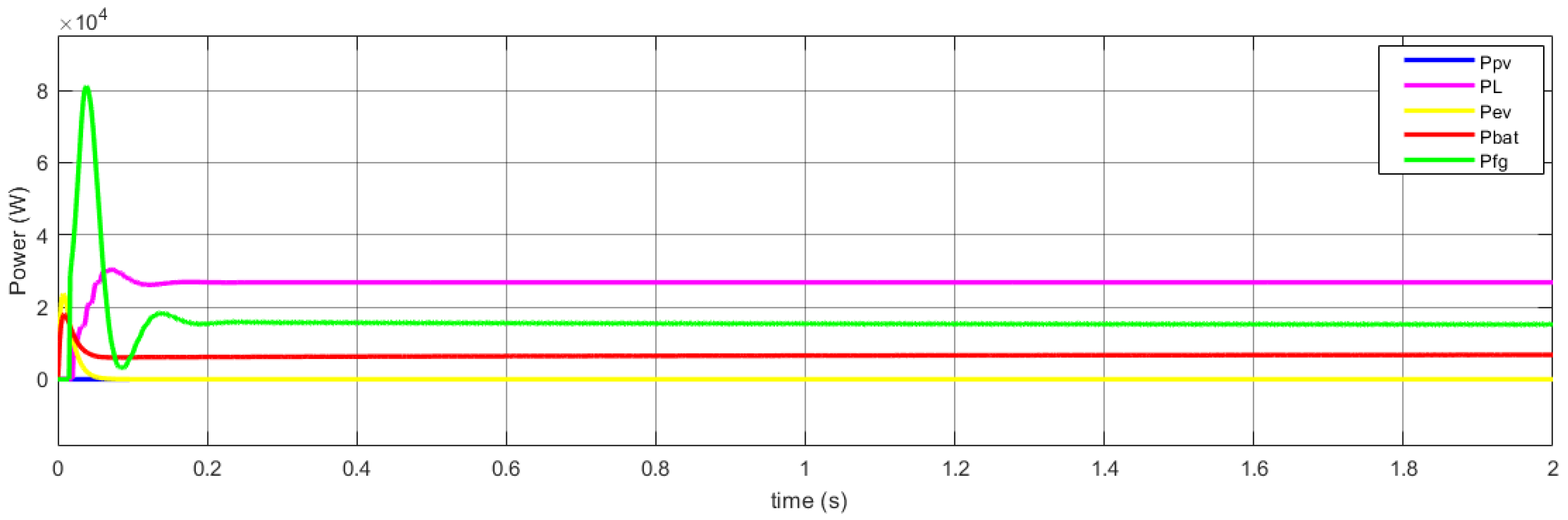
Figure 7 demonstrates the outcomes of the first scenario. The power produced by the PV generator is of higher value and equal to 63 kW. It is able to supply the residential loads with 26 kW power and charge the EV with 7.5 kW charging power and charge the storage battery with a power of 7.3 kW, and there remains about 22.2 kW it is supplied to the electrical grid.
A negative value of the power ( means that the element receives energy (charging the battery/charging the EV/injecting energy into the grid). Contrarywise, the element is providing energy (by depleting the battery, discharging the EV, or using grid electricity) if the power value was positive.
In this case the energy produced through the PV is sufficient to meet the requirements of the household loads, to charge the EV and the storage battery, and the rest of the power is injected into the electricity grid.
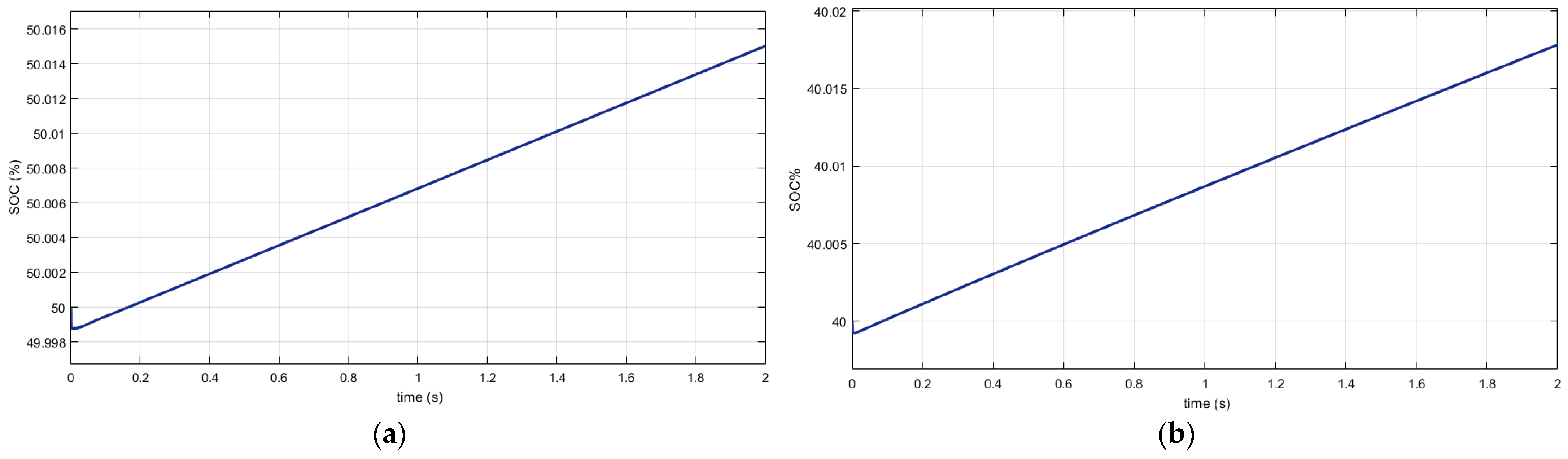
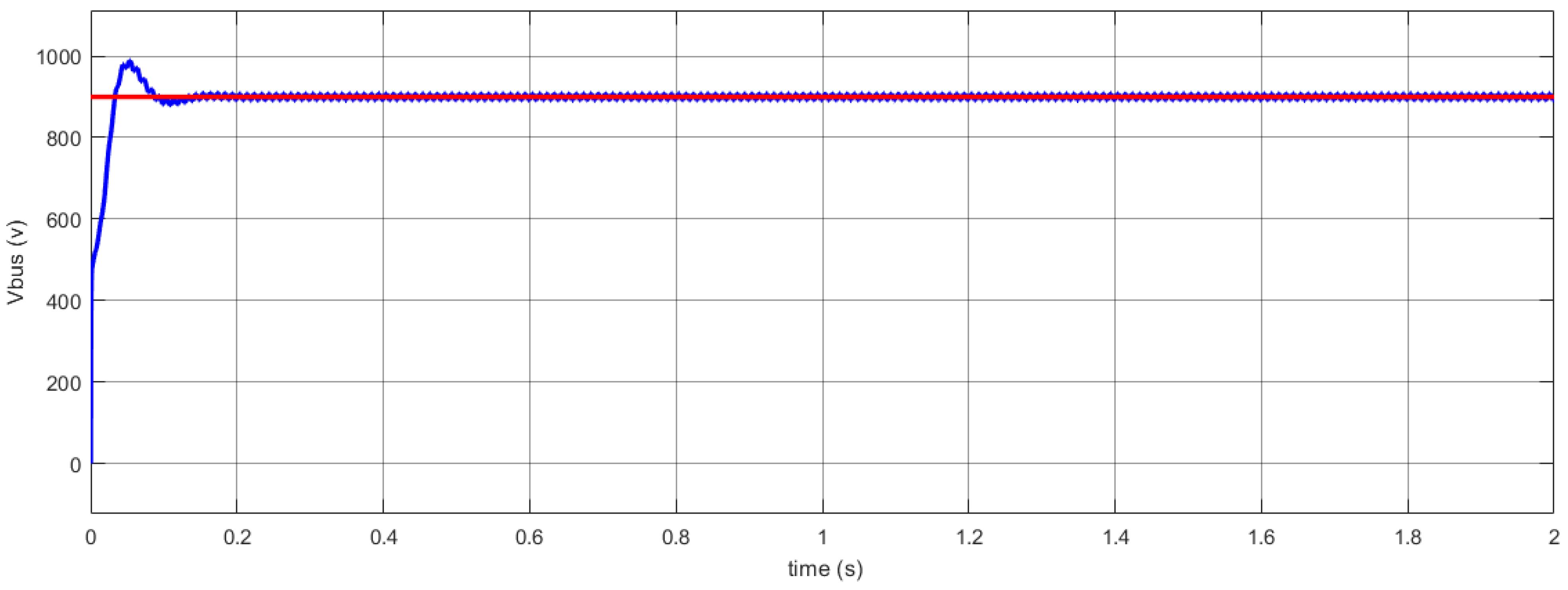
Figure 8a shows EV charging and
Figure 8b shows battery charging, and the DC bus voltage is shown in
Figure 9.
4.1.2. Case 2
In this scenario, the energy generated through the PV generator is of low value, the PV power and the storage battery power are not enough to supply the residential loads. Moreover, since the EV is connected to the house and its charge level is greater than 50%, so it intervenes to meet the demand for household loads, and the electricity grid intervenes to supply the load remaining power of around 8.5 kW as shown in
Figure 10.
The EV operates in this case in V2H mode. It makes use of the energy contained in its battery to power household loads as depicted by
Figure 11.
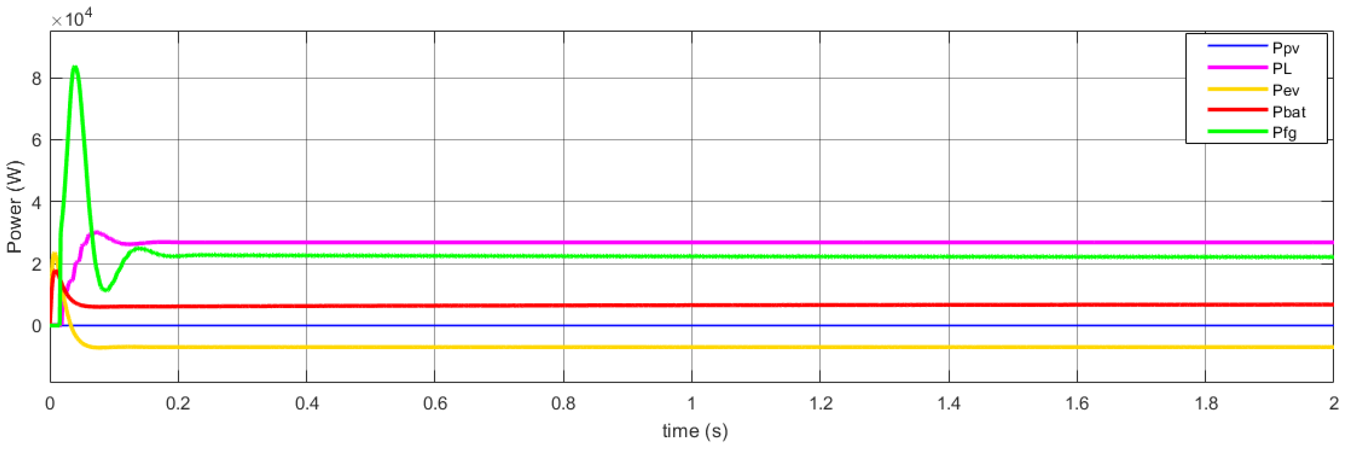
4.1.3. Case 3
As shown by
Figure 12, the PV power and the storage battery power are not enough to supply the residential loads, and the EV is discharged. In this case, the grid intervenes to ensure the load requirements are satisfied, and the EV operates in the H2V mode.
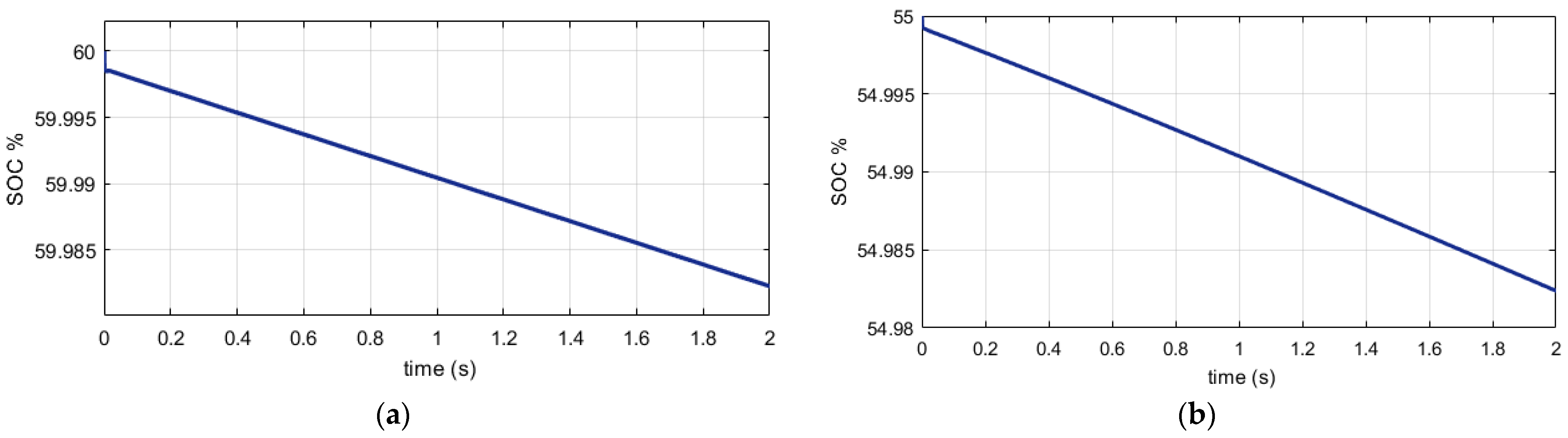
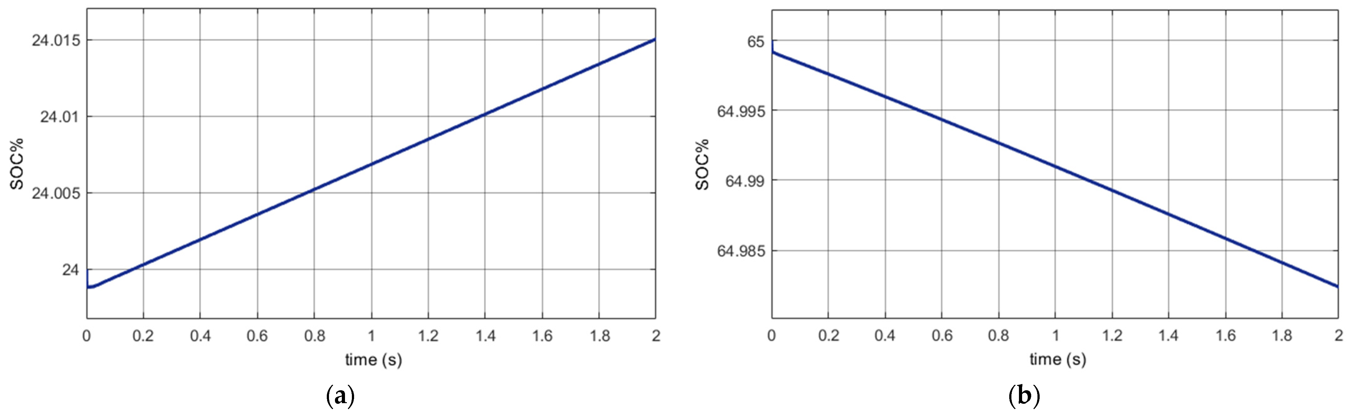
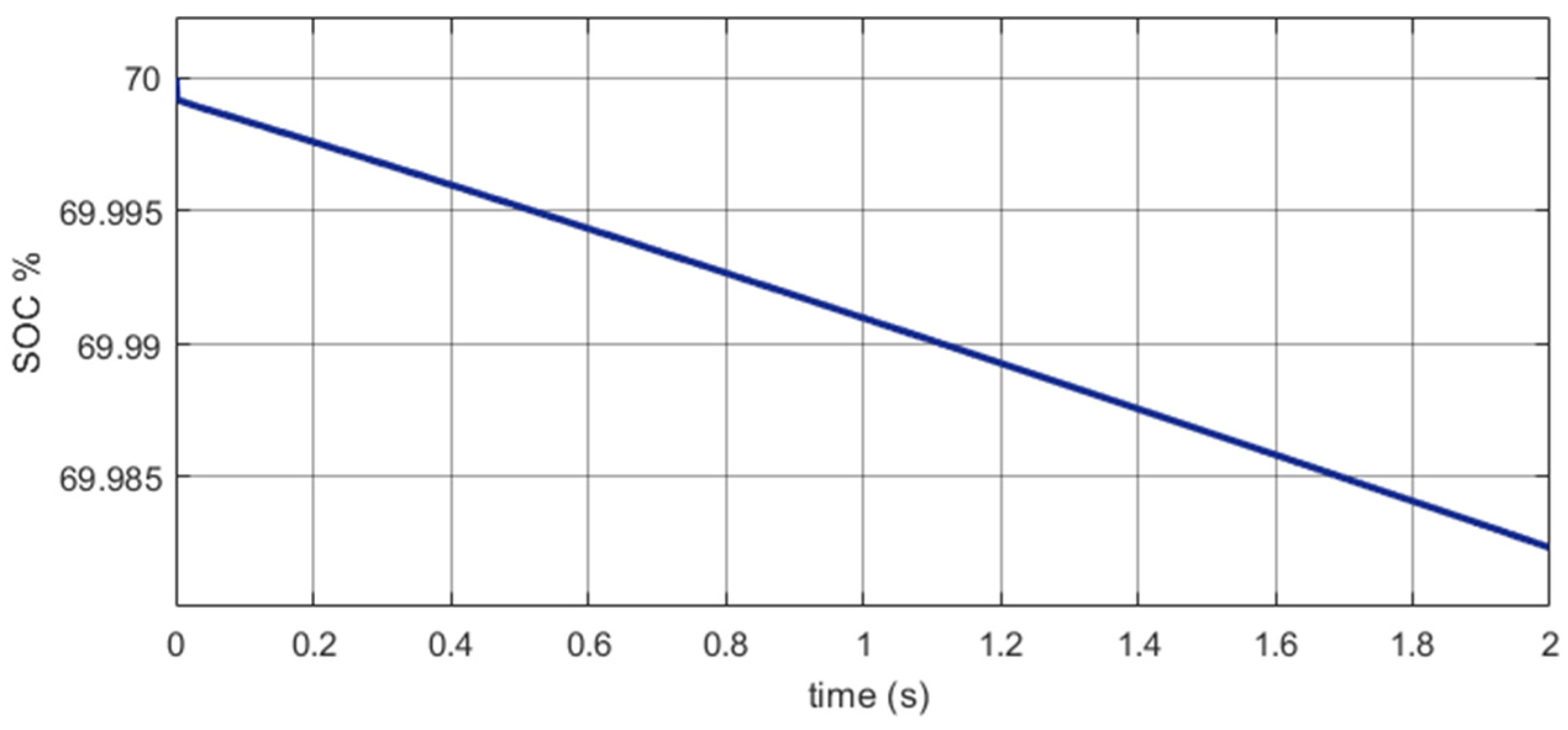
Figure 13 represents the SOC of the EV and the storage battery. The EV operates in H2V mode, it charges through power from storage battery, PV system, and utility grid.
In this case, the EV cannot operate in V2H mode because it is discharged. The grid power used is about 22.5 kW, compared to the previous case (case 2), the grid power has been used was just 8.5 kW. Therefore, the simulation results presented in
Figure 12 show that the use of EV in V2H mode makes it possible to relieve the electrical grid.
4.2. EV Is Not Connected to Home
PV power and storage battery power are not enough to supply residential loads, and the EV is not connected to the house, in this case the grid intervenes to ensure the continuity of service. In this scenario the EV is not connected to the house, it does not intervene in the residential system.
Figure 14 shows that the power of the EV is at zero because the EV is not connected to the home, and the power produced by the PV is low. Therefore, the storage battery, which will be discharged to satisfy the demand of the household loads as shown by
Figure 15, and the electricity grid intervenes to satisfy the load requirements. In this scenario, the power of the grid used is approximately 16 kW. On the other hand, in the same scenario but with the intervention of the EV, the grid uses just a power of 8.5 kW (
Figure 10). This means that the participation of the EV allows to reduce the use of the grid, which leads to the relief of the grid.
5. Summary and Conclusions
The V2H concept is considered an advanced and useful technology, as it can contribute to reducing residential electricity consumption bills and relieving the grid in times of high electricity demand. Most EV owners can benefit from this concept when the EVs are parked at workplace or at home. This work deals with the integration of EV in a residential system operated in a grid-connected mode, and it comprises the PV system, battery storage system, and home loads.
A hybrid control has been suggested to control the different elements of the system, the EV converter is controlled through the combined PI-Fuzzy logic control, which combines the two controls, the conventional PI and the fuzzy logic, the bidirectional AC–DC converter is controlled by ADRC control. The results show the efficiency of the both controllers, the PI-Fuzzy logic controller in reducing voltage and current ripples, and the ADRC controller in rejecting disturbances.
To manage the energy exchange between residential system elements, an energy management system based on the rule-based method is proposed. The suggested EMS addresses all possible scenarios, considering the emergency use of the EV by the owner. All these possible scenarios have been tested and validated.
The simulation results show that the proposed EMS with a residential system integrating V2H technology is a reliable solution that can better handle peak energy demand while simultaneously reducing power grid intervention. The PV is considered as main source, battery for storage, utility grid is used as a backup source. The EV in this work operates in two modes, V2H mode and H2V mode depending on operating conditions. When the energy produced through the PV generator is higher, this power is used to meet the requirements of residential loads and charge the storage batteries and the EV battery to be used when needed (EV operates in H2V mode), and the excess PV energy is injected into the grid. On the contrary, when the energy generated through the PV generator is low, the storage battery and the EV are used to supply the residential loads (EV operates in V2H mode), the electricity grid intervenes to satisfy the load if the power of the battery storage and EV and PV is not enough.


 ,
, 


