Article

The Geometric Configuration of Lubricant Recesses of the Polymer Sliding Layer of the Bearing

by
Anastasia P. Bogdanova
,
Anna A. Kamenskikh
* and
Yuriy O. Nosov
Department of Computational Mathematics, Mechanics and Biomechanics, Perm National Research Polytechnic University, 614990 Perm, Russia
*
Author to whom correspondence should be addressed.
Designs 2023, 7(6), 144; https://doi.org/10.3390/designs7060144
Submission received: 29 October 2023 / Revised: 1 December 2023 / Accepted: 14 December 2023 / Published: 18 December 2023
(This article belongs to the Section Civil Engineering Design)

Abstract

:
Polymers have gained a foothold in the international market and are actively utilized at a large scale in various industries. They are used as sliding layers in various types of friction units. However, there is a lack of research on their deformation behavior under different design conditions. This work is focused on studying the influence of the geometrical design of lubrication recesses in a polymer sliding layer operating under conditions of frictional contact interaction. The article investigated an element of bridge-bearing steel plate with recesses for lubrication. Two geometrical configurations of recesses are studied: the annular groove and spherical well in the engineering software package ANSYS Mechanical APDL. Polytetrafluoroethylene (PTFE) is considered an elastic-plastic sliding layer. A comparative analysis of two models with different geometrical configurations of cutouts for lubrication, with/without taking into account its volume in the recess, has been conducted. The article establishes that in the absence of lubrication in the recesses, large deformations of the polymer sliding layer occur. This effect negatively affects the structure as a whole. Changing the geometry of the recess for lubrication has the greatest effect on the intensity of plastic deformations. Its maximum level is lowered by almost ~60% when spherical notches are used for lubrication instead of grooves. The friction coefficient of the polymer has a great influence on the contact tangential stress. At the experimental coefficient of friction, it is lowered on average by ~85%. The friction coefficient of the lubricant has almost no effect on the deformation of the cell (<1%).

1. Introduction

1.1. Research Objectives

The study objectives are to identify the best set of geometric and frictional parameters based on a comparative analysis of two grease hole configurations with different frictional properties under a wide range of operating loads. We also aim to obtain information on how the presence of lubricant in the lubricant holes affects the deformation of the sliding layer.
Research tasks:
  • To evaluate the performance of sliding layer with grease recesses of different geometries under a wide range of working loads;
  • To evaluate the influence of frictional properties on the deformation behavior of the sliding layer;
  • To evaluate the influence of the presence of lubricant in the recesses designed for it on the deformation behavior of the sliding layer.

1.2. Problem Context

1.2.1. Design Problems of Bridge Bearings

Bridges are one of the major infrastructure elements of transportation systems around the world; however, such structures are not durable. Various factors lead to the deterioration of a bridge structure, especially external loads of natural character [1,2], temperature [3], loads from traffic flows, internal reactions, and the aging of materials. Maintenance and monitoring of the condition of the structure and its load-bearing elements are performed to increase the bridge life resource [4,5]. Also, one of the options for increasing the bearing capacity and bridge service life can be the selection of rational geometry and/or location of its important elements, including the rational geometry of the sliding layer [6], location of the bearing plate of a CEP pile [7], and rational geometry of lubricant recesses [8].
The bearing elements of a bridge support external loads. One of the variants of such structures is bridge bearings [6,8]. Due to the constant increase in the rate of urbanization, it is necessary to constantly improve the performance of bridge bearings by changing their geometric configuration [9,10,11,12,13,14]. Numerous patents exist for different bridge bearings with specific designs to better minimize the effects on construction [9,10], both in terms of lateral [11,13] and earthquake loads [12,14]. Bridge bearings of bridge structures exist in a sufficient variety of construction types. Back in the late 20th and early 21st centuries, the German scientist H. Eggert studied and presented the main geometric variants of bridge bearings [15]. Most of the designs are still actively used and taken as a basis for the creation of new bridge bearings. In recent years, there has been an increase in patent research due to the increasing loads on bridge structures [16]. This is largely connected with the expansion of construction to climatic regions with extreme temperatures (−60/+60) and to seismic active zones.
Minimization of seismic impact on the infrastructure element is an important task. At the same time, bridge performance depends largely on the ability of bridge bearings to fulfill their functions and absorb seismic loads. Researchers consider various improvements and modifications of bridge bearings to expand their functionality [9,10,11,17,18,19,20,21].
In [18], a jack is introduced that can be used for repair works even when seismic vibrations occur, which greatly simplifies works in seismically active zones. In general, there is a large set of work aimed at reducing bridge vibrations, such as the modernization of lead rubber bearings (LRBS) [19] and the study of a combination of different improvements both in the structural elements [20] and in themselves [17]. The Triple Friction Pendulum Bearing (TFPB) with adaptive behavior, which performs a non-linear dynamic analysis of the input data and tunes the system during operation [21], was also introduced. Ref. [22] analyzes the capabilities of bridge bearings to absorb loads, including seismic loads. Timely defect detection or functionality loss of the bridge as a whole, and bridge bearings in particular, are also relevant [23,24]. There is a need for technologies that allow for the prediction of the deformation behavior of structures [25]. Life cycle monitoring technologies for bridge bearings are being actively implemented in bridge construction [25,26], including using robots [27]. If any malfunctions are detected, it is very important to provide fast and quality maintenance of elements in time [28]. For this purpose, new ways of fast installation and replacement of bridge bearings are being developed [29,30]. Numerical models are being developed to quickly analyze the effect of geometric modifications of bridge bearings and their elements on the structure’s serviceability [6,8,31]. Numerical models are usually built using engineering software packages such as ANSYS and LS-DYNA [32].

1.2.2. Material Problems of Antifriction Sliding Layers

Every year, there is an active production development of new antifriction materials, which can be used in various spheres of human activity, including medicine [33,34,35,36], mechanical engineering [37,38,39,40,41], bridge-building activity [42,43], etc. They are applied in different fields for approximately the same type of tasks, namely as a protective and reinforcing coating [38], such as corrosion protection [33], the use of biocompatible polymers as certain grafts [34,35], mouth guards [36], etc. They are used to reduce the size of multifunctional parts and structures [37,39], to reduce friction in bridge bearings [19,41], and in ball or roller bearings [40]. Polymers are used as protective antifrictional layers in bridge bearings. They are used to reduce frictional interaction between contact surfaces [37]. The issue of using modern materials as a sliding layer for a bridge bearing is relevant [6,42].
The study of their physical-mechanical, frictional, operational, thermomechanical, and rheological properties is relevant. Currently, there is a large list of antifriction materials: ultra-high molecular weight polyethylenes with various fillers [43,44], materials based on polytetrafluoroethylene (PTFE) [43], modified polymers, etc. There is a large list of works devoted to the study of the properties of rheological, chemical, physical-mechanical, and frictional materials properties [45,46]. However, a lack of information about the properties of these materials significantly restrains their use [47,48]. A comparative analysis of the sliding layer behavior made of different materials is of interest, especially for different geometric element configurations of bearing [6,8].

1.3. Problem Description

The spherical bearings design includes a contact unit. It consists of an upper steel plate with a spherical segment, a lower steel plate with a cutout for an antifriction layer, and a spherical sliding layer made of polymer material. The design of the bridge spherical bearing in the assembly is shown in Figure 1.
The recess of the lower steel plate under the polymer layer can be polished or have a certain roughness of the “torn thread” type (Figure 1b). The pattern of the interface between the sliding layer and the lower steel plate is not considered in this work. The contact surface of the polymer sliding layer with the spherical segment includes recesses for lubricant. Two options for recesses are considered, including annular grooves (Figure 1c) and spherical holes (Figure 1d).
The bearings absorb loads from the bridge span, which can reach 90 MPa (vertical pressure). The recess geometry for the lubricant can have a significant impact on the structure deformation behavior. Behavior analysis of the bearing, both in the presence of lubrication in the recesses and in its absence (unfavorable case), is of interest for different sliding layer materials. The issue of the geometric arrangement of recesses for lubrication is also relevant [8,49].
This paper deals with the numerical modeling of cavities for lubrication with different geometries. The situations without/with lubrication in cavities are considered. The influence of the geometry of the lubrication cavities on the performance of the structure is investigated. A comparative analysis of the deformation behavior of PTFE sliding layers in a wide range of operating loads has been carried out. Several variations of the friction coefficients of both polymer and lubricant are considered.

2. Materials and Methods

2.1. Materials

The main types of description of material behavior are the following mathematical formulations: elastic, elastic-plastic [43], and viscoelastic-plastic (or a special case of viscoelastic [44]). The problem is solved within the framework of the general mathematical formulation of the problem of contact interaction of elastic bodies with an elastoplastic layer [16,17]. This article considers steel structures and lubricants to be elastic bodies:
σ ^ = λ I 1 ( ε ^ ) I ^ + 2 μ ε ^
where λ and μ are Lame parameters, I 1 ( ε ^ ) is the first invariant of the stress tensor, I ^ is a unit vector, and ε ^ is the strain tensor. The following equation is used for describing large deformations:
ε ^ = [ u ¯ + ( u ¯ ) T + u ¯ ( u ¯ ) T ] / 2 ,
where u ¯ is the displacement vector. The Poisson’s ratio of the lubricant was set at approximately 0.5 (0.49999) and a modulus of elasticity of 2 GPa as a low compressible material to a first approximation. The friction coefficients of the lubricant will be taken as 0.001 and 0.01, which corresponds to the minimum and maximum values of the reference friction coefficient for solid and paste lubricants, respectively [8].
Radiation-modified PTFE is used as the polymeric antifriction material. The physical and mechanical properties of radiation-modified PTFE were obtained by Dr. A.A. Adamov using experimental methods with equipment from the PFIC Ural Branch of the Russian Academy of Sciences. A series of full-scale experiments were carried out to determine the properties of modern polymeric materials of Russian and foreign production, aimed at selecting materials with the best physical-mechanical, frictional, and rheological properties to ensure more favorable deformation behavior. Among the materials considered (experimental studies were performed for more than 30 modern polymers and composites based on them), modified PTFE is noted as one of the promising materials. Figure 2 shows the deformation curve.
The sliding polymer layer is specified as an elastic-plastic body using the deformation theory of elastic-plasticity:
σ ^ = 2 σ I [ ε ^ I 1 ( ε ^ ) I ^ / 3 ] / ( 3 ε I ) + K I 1 ( ε ^ ) I ^ ,
where σ I and ε I are the stress and strain intensity, respectively, and K is the bulk modulus. A series of full-scale experiments to study the frictional properties of materials was carried out using special equipment and original tooling for a limited set of modern polymeric materials and composites based on them in the range of pressures that can be realized by the press used in laboratory studies—up to 54 MPa.
The list of experiments includes hardness measurement by the Brinnell method, tests under uniaxial-deformed state, and uniaxial-stressed state conditions. The experimental study is performed on a Zwick Z100SN5A testing machine (Zwick Roell AG, Ulm, Germany). A Multisens extensometer (Zwick Roell AG, Ulm, Germany) is used to record the history of applied force and vertical displacement. Experimental studies using the Brinnell hardness measurement provide not only the stiffness of the material but also how it deforms inelastically. Single-strain tests allow investigation of the volumetric compressibility of polymeric materials, determination of Poisson’s ratio, and a picture of material deformation as a function of applied pressure (Figure 3).
For the tests, we used the MTS 316 unit with two hydraulic drives for shear tests with compression of the laboratory “Center for Geomechanical Modeling” of the Department “Mineral Deposit Development” of the PNRP University, Perm, Russia. A test specimen in the form of a circular plate with a smooth PTFE surface is taken into consideration. The MTS 316 installation has a maximum vertical load P = 450 kN and a maximum specific load q = 65 MPa, taking into account the edge unloading depending on the height of the free edge of the side surface of the specimen ( h = 2 mm). This value is equal to the height of the polymer above the recess of the bottom plate liner. The diameter of the specimen, considering all of the above, is calculated using the formula:
d = ( 4 P / π q ) 0.5 + 2 h = 103   m m .
Table 1 shows the dimensions and hardness of the specimens before testing. Hardness is measured using the TEMP-4 instrument.
It is then placed in a special tool. The assembly is subjected to cyclic vertical loads and horizontal displacements. The coefficient of friction is calculated for a given pressure. The dependence of the coefficient of friction on the working pressure acting on the specimen is determined after a series of tests. The equipment allows friction coefficients to be obtained for only up to 54 MPa. However, in bridge supports, the range of working pressures is up to 90 MPa. Therefore, the remaining values were determined using approximation functions.
They have the form for PTFE without taking into account lubrication on contact surfaces μ 2 ( P ) = 0.002 + 1.55 / P 17.166 / P 2 + 64.979 / P 3 55.745 / P 4 , and the form while taking into account lubrication is μ 3 ( P ) = 0 . 005 + 0.111 / P + 0.623 / P 2 3.57 / P 3 + 3.335 / P 4 . The error between the experimental data and the approximation function for modified PTFE was less than 1% (Figure 3).
Within the framework of numerical experiments, we will consider three variants of friction contact for a pair of materials steel-modified PTFE with friction coefficients: μ 1 = 0.04 is tabular (reference) friction coefficient; μ 2 ( P ) is friction coefficient obtained from experimental data and corresponding to friction contact without taking into account lubrication on the interface surface; μ 3 ( P ) is friction coefficient obtained from experimental data and corresponding to friction contact with taking into account lubrication on the interface surface.

2.2. Model

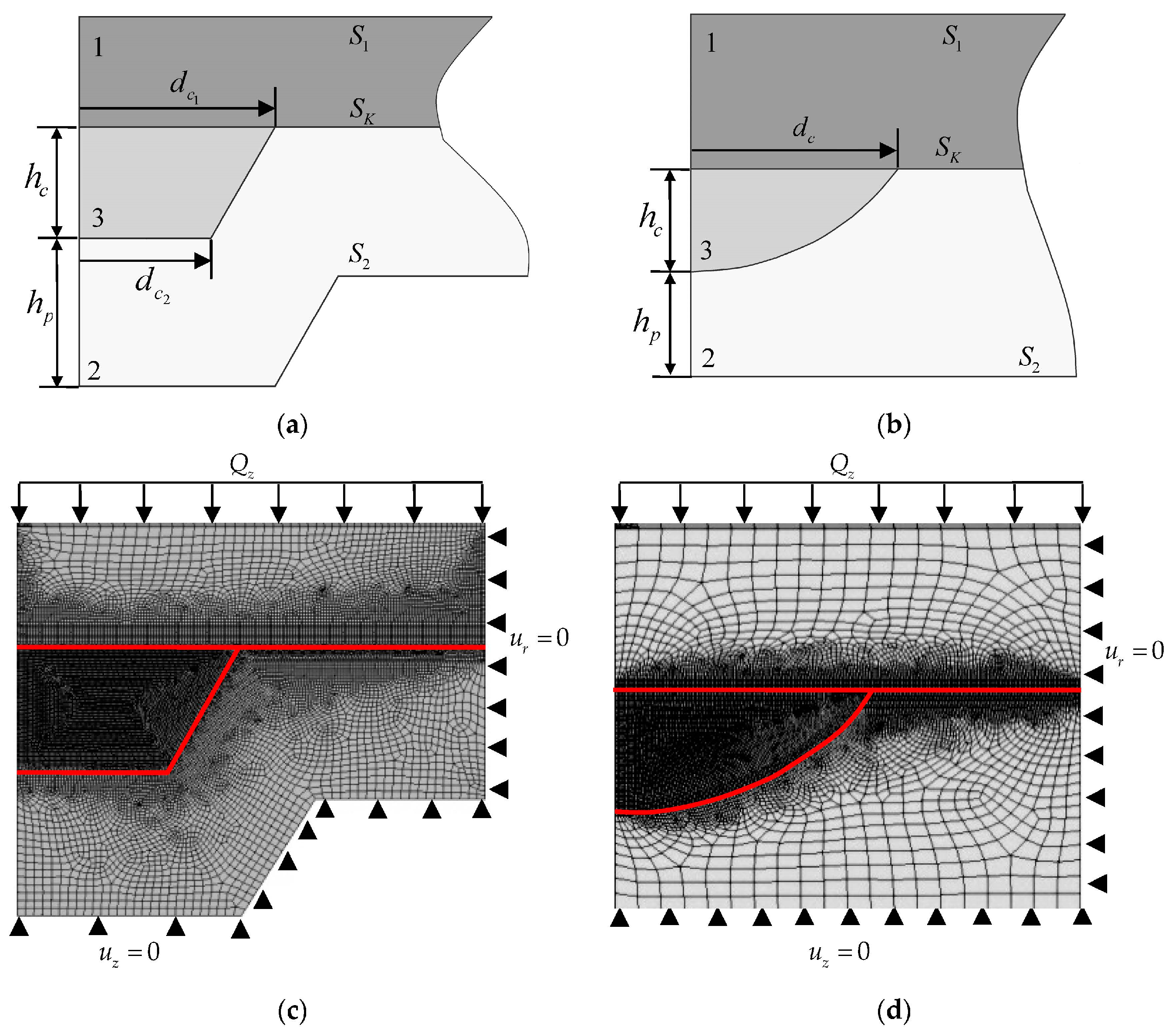
In this paper, numerical modeling of the problem of frictional contact interaction of several bodies is performed. The numerical model was built on the basis of a fragment of a spherical bridge bearing. The fragment includes a steel plate element, an h p = 4 mm-thick polymer antifriction sliding layer with a lubricant recess in the form of a central annular groove (Figure 4a), and a spherical well (Figure 4b).
The following geometric configuration of the annular groove was discussed: h c = 3 mm is the maximum depth; d c 1 = 10.5 mm is the upper diameter; d c 2 = 7 mm is the lower diameter. Geometric configuration of a spherical well: h c = 2 mm is the maximum depth; d c = 8 mm is the diameter.
The equilibrium equation is the basis of the mathematical formulation:
div σ ^ = 0 ,
where σ ^ is the stress tensor.

2.3. Mathematical Boundary and Contact Conditions

The paper considers the results, which were obtained with the software package Ansys Mechanical APDL, using the APDL language. A finite element model is realized, which includes the number of nodes equal to 169 thousand, the minimum equal to 0.125 mm, and the maximum equal to 0.5 mm of mese size. In order to refine the contact parameters near the cavities for the lubricant, it was decided to condense the mesh near its edge, which first contacts the rigid die. The element size in this region was 0.074 mm, increasing the number of node unknowns to 237 thousand. The calculative model is considered in 3D formulation (quarter design). Symmetry conditions are set for an adequate solution. The following boundary conditions are applied on the surface S 1 :
S 1 P d S 1 = Q z ,   u z ( x , y , z S 1 ) = U = c o n s t ,   σ x z = σ y z = 0 ,   x S 1 ,
where Q z is the vertical force applied to S 1 and U is an unknown value. The rest of the outer surfaces are free from loads.
These conditions are assumed because the steel plate interacts with the bridge surface, which has a large stiffness value. Thus, the bending of the surface S 1 is practically eliminated. When the integral over the surface is calculated from the pressure P , a value equal to the applied vertical load is obtained. A pressure ranging from 5 to 90 MPa is applied at the S 1 boundary.
The surface S 2 contains, besides the general mathematical setting of the problem [46], the following boundary conditions (vertical displacements are forbidden):
u z = 0 ,   σ x z = σ y z = 0 ,   x S 2 .
All possible contact boundary conditions (sticking, slippage, and sticking) are studied at the S K boundary:
  • open contact (away from the contact area):
| u n 1 u n 2 | 0 ,   σ n τ 1 = σ n τ 2 = σ n = 0
  • friction slip:
  • for static friction:
u 1 = u 2 ,   σ n 1 = σ n 2 ,   σ n τ 1 1 = σ n τ 1 2 , σ n τ 2 1 = σ n τ 2 2 ,
  • therewith σ n < 0 , σ n τ < μ σ n ,
  • for sliding friction:
u n 1 = u n 2 ,   u τ 1 1 u τ 1 2 , u τ 2 1 u τ 2 2 , σ n 1 = σ n 2 ,   σ n τ 1 1 = σ n τ 1 2 , σ n τ 2 1 = σ n τ 2 2 ,
  • therewith σ n < 0 , σ n τ = μ σ n ,
  • adhesive contact:
u 1 = u 2 ,   σ n 1 = σ n 2 ,   σ n τ 1 1 = σ n τ 1 2 , σ n τ 2 1 = σ n τ 2 2
where μ is the friction coefficient, τ 1 , τ 2 are symbols of coordinate axes lying in the plane tangent to the contact surface, u n is the displacement along the normal to the corresponding contact boundary, u τ 1 ,   u τ 2 are displacements in the tangent plane, σ n is the stress along the normal to the contact boundary, σ n τ 1 ,   σ n τ 2 are tangential stresses at the contact boundary, and σ n τ is the magnitude of the vector of tangential contact stresses.

3. Results

Let us consider the deformation of a polymer interlayer with different geometric configurations of the lubricant recesses. Figure 5 shows the deformation of the sliding layer without/with lubrication in cavities of different geometries.
The steel-polymer friction coefficient has no effect on the deformation of the sliding layer (the difference is less than 1%). This effect is observed with and without lubrication in both cavity geometries. When the cavities are not lubricated, there are significant changes in the cavity profiles. The annular grooves deform significantly but retain their geometry shape. Spherical cavities completely change their geometry under the action of a steel surface. When considering cavities with lubricant, it should be noted that the cavity is pressurized under hydrostatic compression. This effect does not allow the profile of the cavities to change, regardless of their coefficient of friction.
Figure 6 shows the dependence of the maximum level of sliding layer plastic strain without/with lubrication in cavities of different geometries.
It can be seen that the maximum values of plastic deformations have a large level; at the cutout of the annular groove type, the values exceed 600%, which is associated with the overlap of the material, which is not observed at spherical cutouts where the value does not exceed 60%. The influence of friction coefficients on the value of maximum plastic deformations in both types of spherical cutouts is not significant.
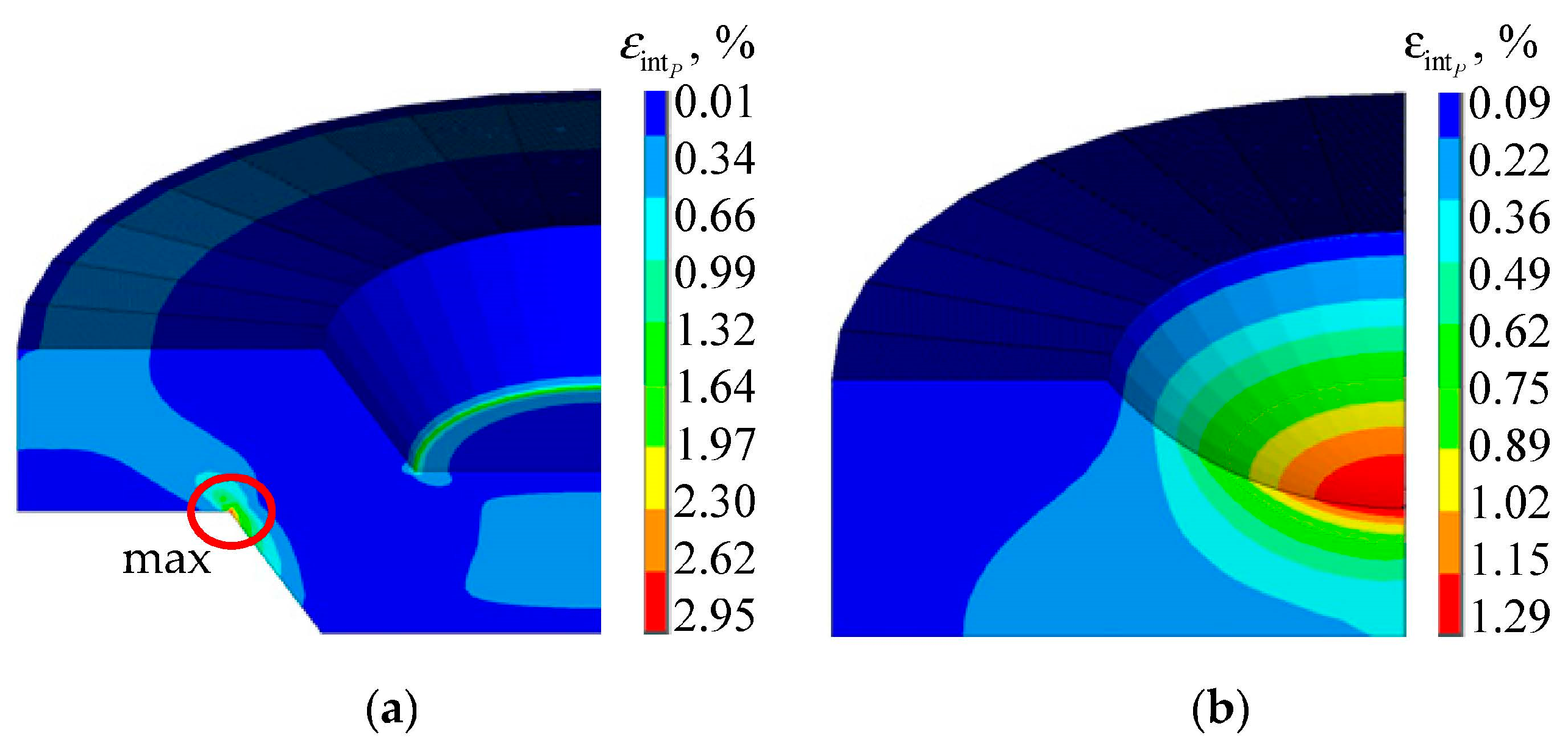
As in the previous case, in the layer with a spherical well, the intensity of plastic deformations is almost two times less than in the design of the contact node with a lubrication recess in the form of an annular groove. When changing the friction coefficient, the maximum values of the parameter practically do not change and are at the same level, with a difference of less than 1%. The distribution of the maximum values of plastic deformations has a nonlinear character, with the minimum value possessing the numerical solution at the friction coefficient, taking into account the lubricant. For a detailed review, it is necessary to consider the isopoles of plastic strain distribution in the material (Figure 7).
At a maximum load of 90 MPa, the volume of material in which plastic deformation is observed in the interlayer with a recess in the form of an annular groove has significantly increased. There is a zone of non-zero intensity of plastic deformations in the central part of the contact node under the recess and a significant zone of plastic deformations near the stress concentrator with an exit to the interface surface of the sliding layer with the steel plate. Spherical notches have a more uniform distribution of plastic deformations; at a distance from the recess, plastic deformations do not exceed 0.1%.
It can be noted that the geometrical configuration of the sliding layer with recesses of the annular groove type is not perfect because, in the lower part of the sliding layer, there is a stress concentrator. To reduce the values of the plastic deformations, an intensity can be proposed for rounding dangerous corners, as well as increasing the thickness of the sliding layer. The thickness can be made 7–8 mm, and the lower surface of the antifriction layer level out.
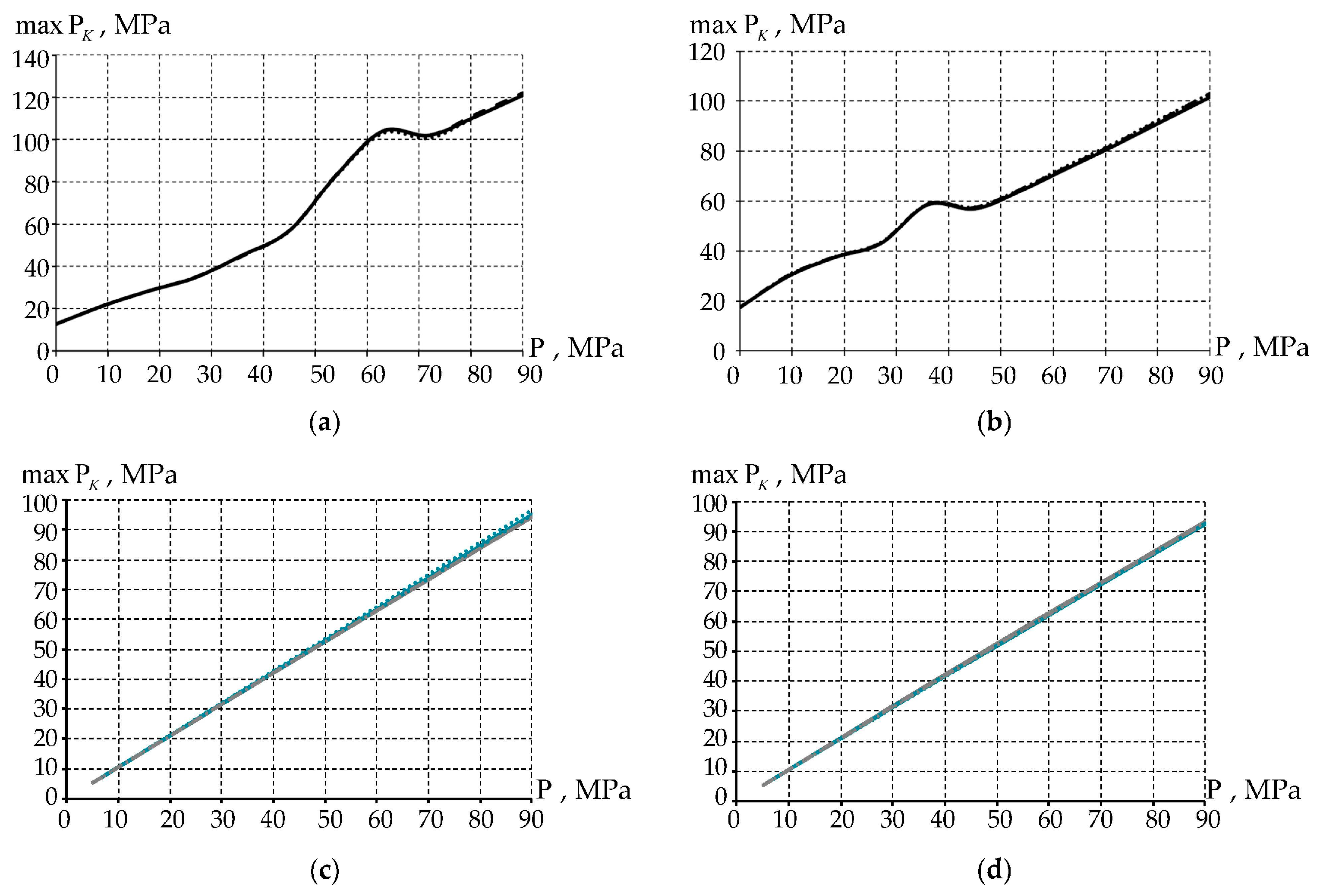
In addition to the deformation characteristics of the material, the parameters of contact interaction play a significant role, including the nature of the distribution of contact states, contact pressure, and contact tangential stress. Figure 8 shows the distribution of contact pressure as a function of load level without/with lubrication in the sliding layer cavities of different geometries.
The distribution of contact pressure has a non-linear character with a characteristic increase in contact pressure (at the annular groove at 60–70 MPa, at spherical notches at 30–40 MPa), which is associated with significant deformation of the contact surface (recesses for lubricant), and redistribution of contact pressure in this area. The use of different friction coefficients does not contribute much to the contact pressure distribution.
The dependence of the maximum level of contact pressure at the contact interaction, taking into account lubrication on the mating surfaces, has a linear character exceeding, on average, by 4 and 2 MPa the pressure applied to the surface of the steel plate for the annular groove and spherical cutout, respectively. The interlayer with the annular groove has, on average, 1–2% higher maximum contact pressure value than the polymer with a spherical notch. Similarly to the case with no lubricant volume in the recess, when using different friction coefficients of polymer and lubricant, the values do not differ significantly—approximately by 3–4%.
Figure 9 shows the tangential contact stresses as a function of load level without/with lubrication in the sliding layer cavities of different geometries.
The lowest value of contact tangential stress has the layer at μ 3 , the highest at the tabulated coefficient of friction. The distribution of contact tangential stress repeats the contact pressure, with the next difference at the annular groove at 60–70 MPa and at the spherical notches at 30–40 MPa. The maximum level of contact tangential stress at contact interaction, taking into account the polymer friction coefficient 0.04, is, on average, three and five times higher than when considering the experimental friction coefficients without taking into account and with taking into account the lubricant, respectively. The character of the distribution of maximum values of contact tangential stress is different. At a friction coefficient of polymer 0.04, linear characters of distribution on all intervals of working pressure are observed. Regarding friction, without taking into account the lubricant, there is a nonlinear character of distribution of the parameter with increasing pressure tends to the asymptote. When examining the experimental coefficient of friction of polymer, taking into account lubricant, we observe a nonlinearity characteristic of the parameter distribution.
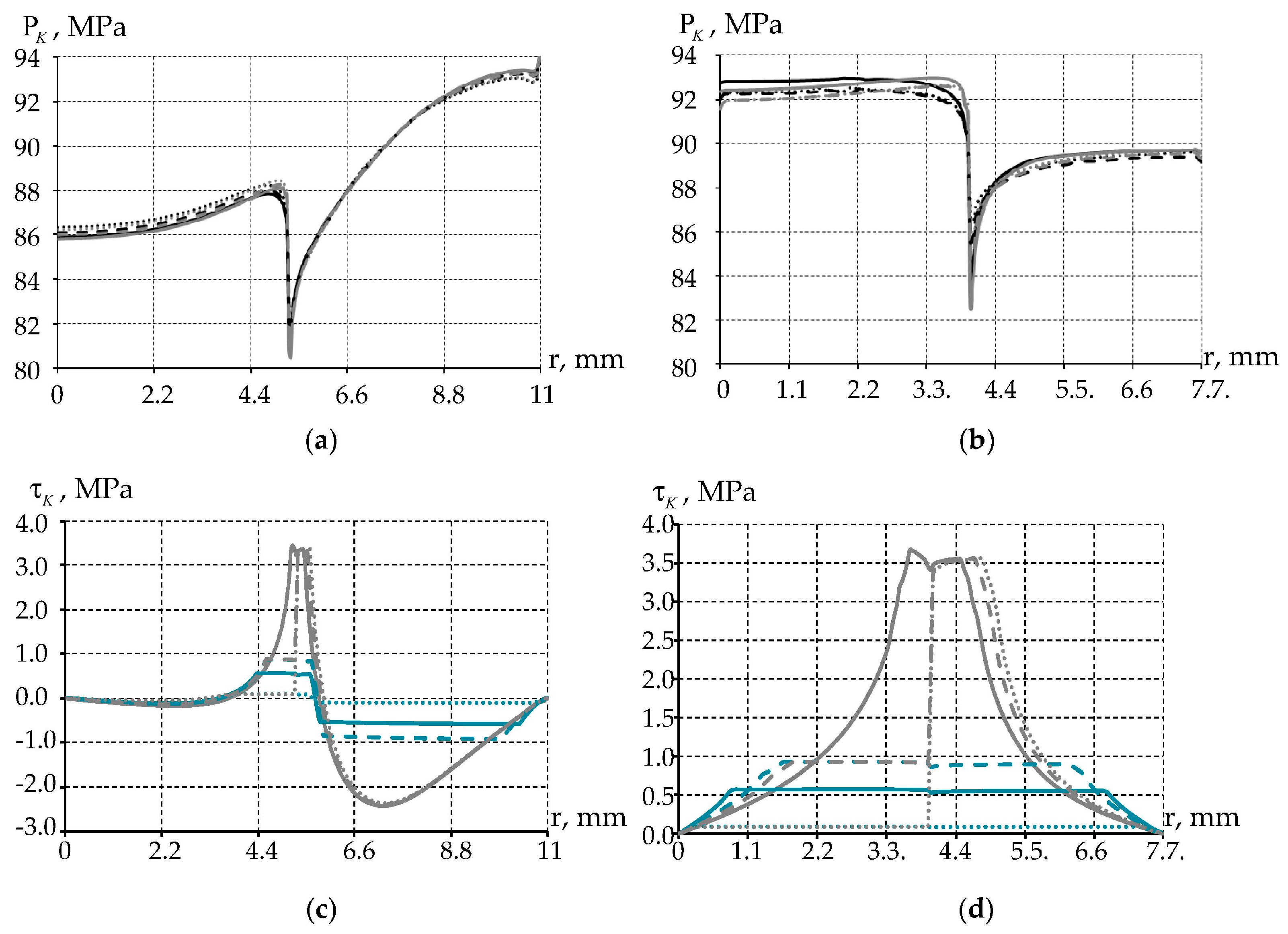
The question of the influence of friction properties of polymer and lubricants on the distribution pattern of contact parameters on the surface S K is interesting (Figure 10). The results are shown for the case of a maximum load of 90 MPa.
The pattern of the contact pressure distribution does not depend on the lubricant friction coefficient. The parameter minimum is observed near the lubricant-polymer interface region. The change in contact pressure in the steel-polymer contact zone is insignificant. The geometry of the recess influences the pattern of the contact pressure distribution in the steel-lubricant contact zone. A nonlinear change in the parameter level from a minimum of 80 MPa to a maximum of 93 MPa is observed with an annular groove, and the pattern of the change in the parameter is more uniform; the maximum does not exceed 90 MPa with a spherical hole.
The distribution of contact tangential stress depends little on the lubricant friction coefficient. This may be due to lubricant hydrostatic compression in the recesses. The polymer frictional properties have the greatest influence on the level of contact tangential stress. An increase in the level of contact tangential stress is observed near the lubricant-polymer interface region, similar to contact pressure. The polymer material exerts significant pressure on the lubricant, which leads to the formation of a maximum parameter zone near the media interface. The recess geometry under the lubricant affects the frictional contact, with a large lubricant volume of negative contact tangential stresses zone appearing, which is observed with an annular groove.
Lubrication grooves in the form of spherical holes allow for a more uniform distribution of contact parameters.

4. Discussion

Investigating the influence of the geometrical configuration of recesses and their filling is an important task. However, it should be noted that the problem is solved only in a static formulation. Accordingly, it does not take into account the thermomechanical effect, rheology, physical and mechanical properties of materials, and type of processing of the contact surface. Also, the influence of such geometrical parameters of the polymer sliding layer, including thickness, depth of embedding into the lower steel plate, etc., were not analyzed. These properties, parameters, and conditions were omitted to simplify the problem. Furthermore, to account for the thermomechanical behavior of the materials, rheology, and so on, further clarification experiments are needed that consider the operating temperatures (−70 °C and +70 °C) and the viscoelastic-plastic behavior of the materials. However, such experiments have not yet been performed. Taking all constraints into account, the dependencies of maximum parameter values depended on cavity geometries, the polymer friction coefficient, and the lubricant friction coefficient (Table 2).
The friction coefficient obtained experimentally is about six times lower than the reference approximation coefficient. And it has the greatest influence on the tangential contact stress. At the experimental friction coefficient, the tangential contact stress is lower from ~74% to ~97% than at μ polym = 0.04, depending on the lubricant friction coefficient. The influence on contact pressure is <1% at almost all positions. And the plastic strain rate becomes <7.2%. Annular groove geometry has the greatest influence on plastic deformation intensity. It has the least influence on contact pressure, which is from 1.06% to 1.25% for μ polym = 0.04, and from 2.1% to 4.22% for μ polym = 0.00631. It has an influence on the contact pressure, which is from 5.35% to 6.28% for μ polym = 0.04 and from 4.49% to 5.04% for μ polym = 0.00631.
Now, PTFE is used in many studies to improve the properties of composites and as an additional coating. PTFE has a number of pre-benefits, including its non-stick properties [48], wear resistance [50], high melting point [51], low coefficient of friction [52], strong insulating properties for electrostatic capacitors [53], etc. For example, in [54], PTFE is used as a sputter on mild steel Q235B, which leads to an increase in the corrosion resistance of the material.
This material is also widely used as a base material for the production of composite materials [54,55,56]. However, a series of studies aimed at analyzing the influence of the percentages of the base and reinforcing elements on the final properties of the materials are necessary to produce high-quality composites. Thus, experiments are conducted to identify specific changes in the behavior of the composite at different concentrations of the PTFE base [54,56] and other materials [41]. PTFE is formed in different ways to obtain composites with different degrees of stiffness [55]. The authors [57] conduct studies aimed at analyzing the influence of the content of reinforcing materials on the wear rate and tribological characteristics when using two types of environmental lubricants (water and glycerin).
However, it is becoming increasingly rare for pure PTFE to be used in various structures or their components. Researchers note that it has lower wear resistance compared to other materials used in bearing parts [58] due to the fact that the lubricant is removed after a certain amount of time, and PTFE ages and crumbles. This is due to its many disadvantages, which in turn are attempted to be eliminated by various modifications or partial replacements. Liu H. et al. [59] studied the performance of PTFE at different temperatures and load effects. It was found that the creep of the material was greater at the average load value of PTFE than under cyclic loading. In addition, the polymer is in different crystalline states at different temperatures, which in turn can complicate the study of its behavior over a wide range of operating temperatures.
However, with the help of such an additive, researchers try to maximize anti-corrosion properties. In addition to polymers, the composite is filled with a large set of different materials, elements, and fibers (particularly fiberglass). Since these materials are often used as antifriction coatings, it is very important to study their tribological properties [40,41,60]. In general, the behavior of materials is influenced not only by operating temperatures and loads but also by the environment, in particular by oxygen and humidity. The concentration of moisture and oxygen in the air can affect the deformation behavior and, consequently, the friction and wear [60]. So, a study on friction properties was carried out by [56], where an attempt was made to increase the wear resistance of PTFE with the help of various modifications. However, the use of PTFE as a protective covering shows an increase in strength and other characteristics [53]. Despite the environmental effects on buildings, it is important to remember the other side of the coin and try to reduce any kind of environmental impact of structures, works, etc., on the environment. Therefore, it is important to try to maximize the use of environmentally friendly lubricants. These lubricants influence the tribological properties of polymers and composites to a greater or lesser extent [57].

5. Conclusions

Within the framework of this research, we have considered the following: without and with lubrication in cavities, two variants of the geometrical configuration of cavities for lubricants, three variants of friction coefficients of steel-polymer contact pairs, and two variants of lubricant friction coefficients contact pairs. Deformation and contact characteristics of the design are obtained, on the basis of which it is established:
-
When the cavities are not lubricated, there are significant changes in the cavity profiles. The annular grooves deform significantly but retain their geometry shape. Spherical cavities completely change their geometry under the action of a steel surface. This effect is observed because there is a void between the spherical notches/groove in the polymer layer and the steel plate, and the polymer deforms greatly under load due to its tendency to fill the void.
-
The steel-polymer friction coefficient has no effect on the deformation of the sliding layer (the difference is less than 1%). This effect is observed with and without lubrication in both cavity geometries.
-
The friction coefficient obtained experimentally is about six times lower than the reference approximation coefficient.
-
It has the greatest influence on the tangential contact stress. At the experimental friction coefficient, the tangential contact stress is lower from ~74% to ~97% than at μ polym = 0.04, depending on the lubricant friction coefficient. The influence on contact pressure is <1% at almost all positions. And the plastic strain rate becomes <7.2%.
-
Annular groove geometry has the greatest influence on plastic deformation intensity. It has the least influence on contact pressure, which is from 1.06% to 1.25% for μ polym = 0.04, and from 2.1% to 4.22% for μ polym = 0.00631. It has an influence on the contact pressure, which is from 5.35% to 6.28% for μ polym = 0.04 and from 4.49% to 5.04% for μ polym = 0.00631. Therefore, spherical notches have a number of advantages in comparison with annular grooves.
-
A significant influence of the set of friction coefficients of the lubricant and the interlayer on the contact parameters of the central part of the interlayer, with a single cutout for the lubricant, is shown.

Author Contributions

Conceptualization, A.A.K., Y.O.N. and A.P.B.; methodology, A.A.K.; software, A.A.K., Y.O.N. and A.P.B.; validation, A.A.K.; writing—original draft preparation, A.A.K., Y.O.N. and A.P.B.; writing—review and editing, Y.O.N. and A.P.B.; visualization, A.A.K., Y.O.N. and A.P.B.; funding acquisition, A.A.K. All authors have read and agreed to the published version of the manuscript.

Funding

This research was funded by the Ministry of Science and Higher Education of the Russian Federation (Project No. FSNM-2023-0007).

Data Availability Statement

The data presented in this study are available on request from the corresponding author. The data are not publicly available due to internal data dissemination procedures.

Conflicts of Interest

The authors declare no conflict of interest.

References

  1. Tian, Y.; Wang, P.; Wang, M. Pressure Characteristics of Landslide-Generated Waves on Bridge Piers. Water 2023, 15, 3623. [Google Scholar] [CrossRef]
  2. Cooper, A.H.; Saunders, J.M. Road and bridge construction across gypsum karst in England. Eng. Geol. 2002, 65, 217–223. [Google Scholar] [CrossRef]
  3. Wang, L.; Yu, L.; Du, X.; Zhang, X.; Li, Z. Seismic Response of a PC Continuous Box Girder Bridge under Extreme Ambient Temperature. Sustainability 2023, 15, 14763. [Google Scholar] [CrossRef]
  4. Han, D.; Hosamo, H.; Ying, C.; Nie, R. A Comprehensive Review and Analysis of Nanosensors for Structural Health Monitoring in Bridge Maintenance: Innovations, Challenges, and Future Perspectives. Appl. Sci. 2023, 13, 11149. [Google Scholar] [CrossRef]
  5. Sonbul, O.S.; Rashid, M. Towards the Structural Health Monitoring of Bridges Using Wireless Sensor Networks: A Systematic Study. Sensors 2023, 23, 8468. [Google Scholar] [CrossRef]
  6. Adamov, A.A.; Kamenskikh, A.A.; Pankova, A.P.; Strukova, V.I. Comparative Analysis of the Work of Bridge Spherical Bearing at Different Antifriction Layer Locations. Lubricants 2022, 10, 207. [Google Scholar] [CrossRef]
  7. Qian, Y.; Sun, L.; Ai, L.; Zhou, Y.; Li, M. Theoretical Analysis of the Influence of Bearing Plate Position on the Bearing Performance of Soil around the CEP Antipull Force Double Pile. Buildings 2023, 13, 2613. [Google Scholar] [CrossRef]
  8. Nosov, Y.O.; Kamenskikh, A.A. Influence Analysis of Lubricant Recesses on the Working Capacity of the Bridge Span Spherical Bearing. Lubricants 2022, 10, 283. [Google Scholar] [CrossRef]
  9. Buckle, I.G.; Built, S.M. Cyclic Shear Energy Absorber. US4499694A, 19 February 1985. [Google Scholar]
  10. Fyfe, E.R.; Kelly, J.M. System and Apparatus for Limiting the Effect of Vibrations between a Structure and Its Foundation. US5014474A, 14 May 1991. [Google Scholar]
  11. Fyfe, E.R.; Slater, W.M.; Watson, R.J. Aseismic Bearing for Bridge Structures. US4617769A, 24 February 2004. [Google Scholar]
  12. Shaferman, I.M.; Gitman, E.M.; Doroshkevich, A.A.; Bukanov, V.V.; Kopytov, A.V.; Bukanova, E.V. Bearing. RU92667U1, 27 March 2010. (In Russian). [Google Scholar]
  13. Bukanov, V.V.; Ipanov, A.S.; Hatipov, S.A.; Adamov, A.A.; Ostrer, S.G. Bearing. RU146859U1, 20 October 2014. (In Russian). [Google Scholar]
  14. Zijun, C.; Jinzhao, G.; Yuan, G.; Wanliang, C. High Damping Rubber Bridge Damping Support. CN217419297U, 13 September 2022. [Google Scholar]
  15. Eggert, H.; Grote, J.; Kauschke, W. Lager im Bauwesen; Ernst & Sohn: Berlin, Germany, 1974. [Google Scholar]
  16. Shepitko, T.V.; Lutsky, S.Y.; Nak, G.I.; Cherkasov, A.M. Technological Features of Construction and Reconstruction of Geotechnical Structures in the Arctic Zone. Designs 2022, 6, 34. [Google Scholar] [CrossRef]
  17. Jizhong, Y.; Lie, C.; Kejian, C.; Yingliang, W.; Yinguang, X.; Wanming, Z.; Yongxing, W.; Mingjun, L.; Chengbiao, C.; Yongping, Z.; et al. Method for Improving Seismic Performance of Bridge by Using Beam Body and Energy Dissipation and Seismic Mitigation Bridge Bearing. US10815627B2, 27 October 2020. [Google Scholar]
  18. Cha, H. Two-Way c.p.s Jack Having Earthquake-Proof Function Using for Intensity Reinforce Mathod for Bridge Bearing and Lifting Method for Structure Using the Same. KR102055925B1, 16 December 2019. [Google Scholar]
  19. Gupta, P.K.; Ghosh, G.; Kumar, V.; Paramasivam, P.; Dhanasekaran, S. Effectiveness of LRB in Curved Bridge Isolation: A Numerical Study. Appl. Sci. 2022, 12, 11289. [Google Scholar] [CrossRef]
  20. Ghazal, H.; Mwafy, A. Comparative Performance Evaluation of Retrofit Alternatives for Upgrading Simply Supported Bridges Using 3D Fiber-Based Analysis. Buildings 2023, 13, 1161. [Google Scholar] [CrossRef]
  21. Moeindarbari, H.; Taghikhany, T. Seismic optimum design of triple friction pendulum bearing subjected to near-fault pulse-like ground motions. Struct. Multidisc. Optim. 2014, 50, 701–716. [Google Scholar] [CrossRef]
  22. Park, S.K.; Han, K.B. Effects of seismic isolation bearing with sliding mechanism on the response of bridge. Mater. Struct. 2004, 37, 412–421. [Google Scholar] [CrossRef]
  23. Ningbo, W.; De, Z.; Fanglin, H.; Xinkui, T.; Dongping, L. Bridge bearing capacity evaluation method based on mobile load test. CN110377943B, 25 February 2022. [Google Scholar]
  24. Orfeo, A.; Tubaldi, E.; McAlorum, J.; Perry, M.; Ahmadi, H.; McDonald, H. Self-Sensing Rubber for Bridge Bearing Monitoring. Sensors 2023, 23, 3150. [Google Scholar] [CrossRef]
  25. Kim, B.-s. Displacement Gauge for Bridge Bearing and Bridge Bearing with Same. KR102120979B1, 10 June 2020. [Google Scholar]
  26. Bin, Y.; Ye, X.; Xinmin, Z.; Xingzhong, Z. Elastic Spherical Support for Bridge. CN111472267B, 30 November 2021. [Google Scholar]
  27. Peel, H.; Luo, S.; Cohn, A.G.; Fuentes, R. Localisation of a mobile robot for bridge bearing inspection. Autom. Constr. 2018, 94, 244–256. [Google Scholar] [CrossRef]
  28. Deng, Y.; Li, A. Structural Health Monitoring for Suspension Bridges; Springer: Beijing, China, 2019. [Google Scholar]
  29. Xing, Z.; Jing, L.; Guangyang, L.; Zhi, T.; Fengjing, D. Bridge support capable of being partially replaced and replacement method. CN111321677B, 28 September 2021. [Google Scholar]
  30. Liu, J.; Liu, L.; He, J.; Zi, D.; Lv, X.; Luo, Q.; Mo, Q.; Lan, Z.; Huang, S.; Li, L. Rapid installation and replacement method of bridge shock insulation rubber support. CN111648254B, 22 October 2021. [Google Scholar]
  31. Rajczyk, J.; Rajczyk, M.; Lazarev, Y.; Rajczyk, P.; Kirillova, D. Elastomer Bearing Modification for Efficient Design. Lect. Notes Civ. Eng. 2020, 70, 715–726. [Google Scholar]
  32. Wu, Y.; Wang, H.; Li, A.; Feng, D.; Sha, B.; Zhang, Y. Explicit finite element analysis and experimental verification of a sliding lead rubber bearing. J. Zhejiang Univ. -Sci. A 2017, 18, 363–376. [Google Scholar] [CrossRef]
  33. Lu, A.-H.; Salabas, E.-L.; Schuth, F. Magnetic nanoparticles: Synthesis, protection, functionalization and application. Angew. Chem. Int. Ed. 2007, 46, 1222–1244. [Google Scholar] [CrossRef]
  34. Wenhao, W.; Kelvin, W.K.Y. Bone grafts and biomaterials substitutes for bone defect repair: A review. Bioact. Mater. 2017, 2, 224–247. [Google Scholar] [CrossRef]
  35. Recek, N. Biocompatibility of Plasma-Treated Polymeric Implants. Materials 2019, 12, 240. [Google Scholar] [CrossRef]
  36. Gould, T.E.; Piland, S.G.; Shin, J.; Hoyle, C.E.; Nazarenko, S. Characterization of mouthguard materials: Physical and mechanical properties of commercialized products. Dent. Mater. 2009, 25, 771–780. [Google Scholar] [CrossRef] [PubMed]
  37. Forintos, N.; Czigany, T. Multifunctional application of carbon fiber reinforced polymer composites: Electrical properties of the reinforcing carbon fibers—A short review. Compos. Part B Eng. 2019, 162, 331–343. [Google Scholar] [CrossRef]
  38. Ren, Y.; Zhang, L.; Xie, G.; Li, Z.; Chen, H.; Gong, H.; Xu, W.; Guo, D.; Luo, J. A review on tribology of polymer composite coatings. Friction 2021, 9, 429–470. [Google Scholar] [CrossRef]
  39. Doh, J.; Hur, S.H.; Lee, J. Viscoplastic parameter identification of temperature-dependent mechanical behavior of modified polyphenylene oxide polymers. Polym. Eng. Sci. 2019, 59, E200–E211. [Google Scholar] [CrossRef]
  40. Dai, W.; Zuo, J.; Liu, D.; Guo, X. Tribological Properties and Seasonal Freezing Damage Evolution of Rotating Spherical Hinge Self-Lubricating Coating. Appl. Sci. 2022, 12, 8329. [Google Scholar] [CrossRef]
  41. Birleanu, C.; Pustan, M.; Cioaza, M.; Bere, P.; Contiu, G.; Dudescu, M.C.; Filip, D. Tribo-Mechanical Investigation of Glass Fiber Reinforced Polymer Composites under Dry Conditions. Polymers 2023, 15, 2733. [Google Scholar] [CrossRef] [PubMed]
  42. Adamov, A.; Kamenskikh, A.; Nosov, Y. Analysis of deformation behavior of the antifriction layer part with a spherical recess for lubricant. AIP Conf. Proc. 2021, 2371, 020005. [Google Scholar] [CrossRef]
  43. Yi, X.-S.; Luo, S.; Zhang, L. Composite Materials Engineering; Springer: Singapore, 2018; Volume 1. [Google Scholar] [CrossRef]
  44. Kamenskih, A.A.; Trufanov, N.A. Numerical analysis of the stress state of a spherical contact system with an interlayer of antifriction material. Comput. Contin. Mech. 2013, 6, 54–61. [Google Scholar] [CrossRef]
  45. Ushakov, A.V.; Karpov, I.V.; Fedorov, L.U.; Lepeshev, A.A. Mechanical and tribological properties of complex-modified material based on ultra high molecular weight polyethylene and CuO. J. Frict. Wear 2014, 35, 7–11. [Google Scholar] [CrossRef]
  46. Kamenskih, A.A.; Trufanov, N.A. Regularities of interactions between elements of a spherical contact unit with an antifriction polymeric interlayer. J. Frict. Wear 2015, 36, 170–176. [Google Scholar] [CrossRef]
  47. Adamov, A.A.; Kamenskikh, A.A.; Nosov, Y.O. Deformational behavior of the flat sliding layer of the spherical bearing. Int. J. Civ. Eng. Technol. (IJCIET) 2019, 10, 99–107. [Google Scholar]
  48. Guerrero-Vaca, G.; Rodríguez-Alabanda, O. Analysis of Wear Phenomena Produced by Erosion with Abrasive Particles against Fluoropolymeric Coatings. Polymers 2022, 14, 4617. [Google Scholar] [CrossRef] [PubMed]
  49. Nosov, Y.O.; Kamenskikh, A.A. Experimental study of the rheology of grease by the example of ciatim-221 and identification of its behavior model. Lubricants 2023, 11, 295. [Google Scholar] [CrossRef]
  50. Stolbova, O.S.; Tihomirova, K.A. Two methods for calculating the stress-strain state of shape memory alloy constructions taking into account tension–compression asymmetry. PNRPU Mech. Bull. 2020, 1, 109–125. [Google Scholar] [CrossRef] [PubMed]
  51. Wang, H.; Liu, X.; Liu, J.; Wu, M.; Huang, Y. Tailoring Interfacial Adhesion between PBAT Matrix and PTFE-Modified Microcrystalline Cellulose Additive for Advanced Composites. Polymers 2022, 14, 1973. [Google Scholar] [CrossRef] [PubMed]
  52. Zhang, X.; Yao, Z.; Du, H.; Song, J.; Jin, Z.; Xu, W. Wettability and Frictional Studies of PEEK Composites against Co-Cr Alloys with Surface Textures. Polymers 2023, 15, 4006. [Google Scholar] [CrossRef] [PubMed]
  53. Meng, X.-S.; Zhou, Y.; Li, J.; Ye, H.; Chen, F.; Zhao, Y.; Pan, Q.; Xu, J. All-Organic PTFE Coated PVDF Composite Film Exhibiting Low Conduction Loss and High Breakdown Strength for Energy Storage Applications. Polymers 2023, 15, 1305. [Google Scholar] [CrossRef]
  54. Liang, X.; Wu, P.; Lan, L.; Wang, Y.; Ning, Y.; Wang, Y.; Qin, Y. Effect of Polytetrafluoroethylene (PTFE) Content on the Properties of Ni-Cu-P-PTFE Composite Coatings. Materials 2023, 16, 1966. [Google Scholar] [CrossRef]
  55. Mei, S.; Zhou, C.; Hu, Z.; Xiao, Z.; Zheng, Q.; Chai, X. Preparation of a Ni-P-nanoPTFE Composite Coating on the Surface of GCr15 Steel for Spinning Rings via a Defoamer and Transition Layer and Its Wear and Corrosion Resistance. Materials 2023, 16, 4427. [Google Scholar] [CrossRef]
  56. Qi, Y.; Sun, B.; Zhang, Y.; Gao, G.; Zhang, P.; Zheng, X. Tribological Properties of Nano-ZrO2 and PEEK Reinforced PTFE Composites Based on Molecular Dynamics. Lubricants 2023, 11, 194. [Google Scholar] [CrossRef]
  57. Trajkovski, A.; Novak, N.; Pustavrh, J.; Kalin, M.; Majdič, F. Performance of Polymer Composites Lubricated with Glycerol and Water as Green Lubricants. Appl. Sci. 2023, 13, 7413. [Google Scholar] [CrossRef]
  58. Han, O.; Kwark, J.-W.; Lee, J.-W.; Han, W.-J. Analytical Study on the Frictional Behavior of Sliding Surfaces Depending on Ceramic Friction Materials. Appl. Sci. 2023, 13, 234. [Google Scholar] [CrossRef]
  59. Liu, H.; Zhang, L.; Lu, K.; Gao, B. Study of Cyclic Plasticity and Creep Ratchet Behavior of PTFE. Appl. Sci. 2023, 13, 10039. [Google Scholar] [CrossRef]
  60. Johansson, P.; Marklund, P.; Björling, M.; Shi, Y. Effect of Oxygen and Moisture on the Friction and Wear of Carbon Fiber-Reinforced Polymers. Lubricants 2023, 11, 412. [Google Scholar] [CrossRef]
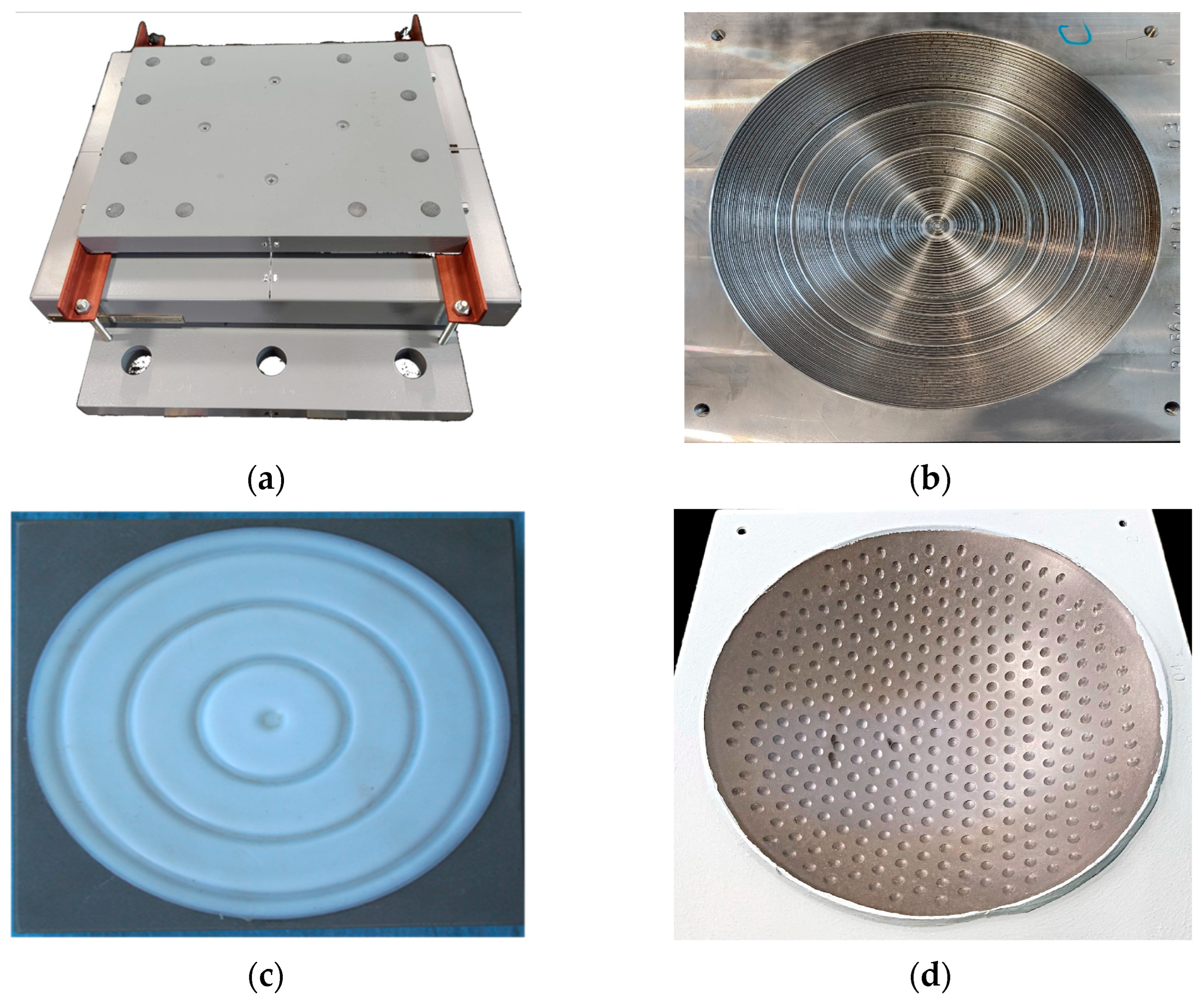
Figure 1. Spherical bridge bearing: (a) is assembled structure; (b) is one of the options for surface treating of the lower steel plate under a polymer layer; (c) is polymer layer with cylindrical grooves for lubricant; (d) is polymer layer with spherical holes for lubricant.
Designs 07 00144 g001
Figure 2. The modified PTFE deformation curve ( σ ε ).
Designs 07 00144 g002
Figure 3. The dependence of friction coefficient on pressure for modified PTFE: 1 is experimental data without taking into account lubrication; 2 is an approximation of experimental data without taking into account lubrication; 3 is experimental data with taking into account lubrication; 4 is an approximation of experimental data with taking into account lubrication.
Designs 07 00144 g003
Figure 4. Calculation schemes of the model problem: (a) is annular groove; (b) is spherical notches; 1 is steel plate; 2 is polymer interlayer; 3 is lubricant; (c,d) finite element scheme annular groove and spherical notch respectively.
Designs 07 00144 g004
Figure 5. Deformation behavior of the sliding layer at a load of 90 MPa, without (a,b) and with (c,d) lubrication in cavities of different geometries: (a,c) are annular grooves; (b,d) are spherical notches; red lines are undeformed geometry; black lines are deformed geometry with difference coefficient of lubricant friction ( μ 1 is solid; μ 2 is dotted; μ 3 is points).
Designs 07 00144 g005
Figure 6. Maximum plastic strain values as a function of pressure without (a,b) and with (c,d) lubrication in cavities of different geometries: (a,c) are annular grooves; (b,d) are spherical notches; for (a,b): μ 1 is solid; μ 2 ( P ) is dotted; μ 3 ( P ) is points; for (c,d): gray lines are μ 1 ; blue lines are μ 3 ( P ) ; lubricant friction coefficient: solid line is μ polym = μ lubric ; dashed line is μ lubric = 0.01 points line is μ lubric = 0.001.
Designs 07 00144 g006
Figure 7. Plastic deformation intensity at a load of 90 MPa, taking into account the volume of lubricant in the recess: (a) is annular groove; (b) is spherical notches.
Designs 07 00144 g007
Figure 8. Addiction of contact pressure as a function of load level without (a,b)/with (c,d) lubrication in cavities of different geometries: (a,c) is annular groove; (b,d) is spherical notches; for (a,b): μ 1 is solid; μ 2 ( P ) is dotted; μ 3 ( P ) is points; for (c,d): gray lines are μ 1 ; blue lines are μ 3 ( P ) ; lubricant friction coefficient: solid line is μ polym = μ lubric ; dashed line is μ lubric = 0.01 points line is μ lubric = 0.001.
Designs 07 00144 g008
Figure 9. Contact tangential stresses as a function of the load level without (a,b) and with (c,d) lubrication in cavities of different geometries: (a,c) are annular grooves; (b,d) are spherical notches; for (a,b): μ 1 is solid; μ 2 is dotted; μ 3 is points; for (c,d): gray lines are μ 1 ; blue lines are μ 3 ; lubricant friction coefficient: solid line is μ polym = μ l u b r i c ; dashed line is μ lubric = 0.01 points line is μ lubric = 0.001.
Designs 07 00144 g009
Figure 10. Distribution of contact parameters over the contact surface, without (a,b) and with (c,d) lubrication in cavities of different geometries at a load of 90 MPa: (a,b) are contact pressures; (c,d) are contact tangential stresses; (a,c) are annular grooves; (b,d)are spherical notches; for (a,b): μ 1 is solid; μ 2 is dotted; μ 3 is points; the black line is the coefficient of lubricant friction 0.01; the gray line is the coefficient of lubricant friction 0.001; for (c,d): gray lines are μ 1 ; blue lines are μ 3 ; lubricant friction coefficient: solid line is μ polym = μ lubric ; dashed line is μ lubric = 0.01 points line is μ lubric = 0.001.
Designs 07 00144 g010
Table 1. Size and hardness of the original PTFE specimens.
Measurement TimeDiameter d , mmThickness, H mmHeight h , mmHardness HB
Before testing103.46–103.5010.582.73409
After testing103.62–104.7510.482.63482
Reduced specimens after turning of tested specimens97.9–98.04.841.0–1.3292
After testing of reduced specimens99.0–99.14.800.3–0.5308
Table 2. Maximum values of main parameters at 90 MPa load for all lubricant and polymer friction coefficients for both cavities.
Def. and Cont. ParametersSpherical NotchesAnnular Groove
μ polym = μ lubric μ lubric = 0.01 μ lubric = 0.001 μ polym = μ lubric μ lubric = 0.01 μ lubric = 0.001
μ polym = 0.04
max ε int P , %0.01460.01420.01320.03000.03060.0308
maxP K , MPa93.172892.966692.977794.167994.134094.1499
max τ K , MPa3.65803.55573.55803.44203.36703.3775
μ polym = 0.00631 (for load at 90 MPa)
max ε int P , %0.01360.01400.01270.03010.03020.0301
maxP K , MPa92.410292.552892.601895.063394.543996.6795
max τ K , MPa0.58270.92540.09260.55750.88100.0886
Comparison model with different friction coefficient
Δ ε int P , %7.18251.52613.66840.18091.46262.3531
Δ P K , %0.81850.44510.40430.95080.43542.6868
Δ τ K , %84.07173.974397.397483.803073.835597.3761
Disclaimer/Publisher’s Note: The statements, opinions and data contained in all publications are solely those of the individual author(s) and contributor(s) and not of MDPI and/or the editor(s). MDPI and/or the editor(s) disclaim responsibility for any injury to people or property resulting from any ideas, methods, instructions or products referred to in the content.