Communication

Modification of a Grain Moisture Conditioner into a Vacuum Steam Pasteurizer

Department of Agricultural and Biosystems Engineering, North Dakota State University, Fargo, ND 58108, USA
*
Author to whom correspondence should be addressed.
Submission received: 3 November 2023 / Revised: 11 December 2023 / Accepted: 18 December 2023 / Published: 21 December 2023

Abstract

:
Eliminating microbes in low-moisture foods (LMFs) is challenging because this requires the preservation of their raw quality during pasteurization. Vacuum steam pasteurization (VSP) has been shown to be effective in reducing microbes while maintaining food quality. These studies were conducted at a laboratory scale where issues such as steam distribution, penetration, and condensation are not a concern, but in larger samples, these are of primary concern. Hence, this study repurposes a pilot-scale grain moisture conditioner (GMC) into a VSP system with the aim of replicating the lab-scale conditions in larger-scale applications. The modification entailed a series of design alterations, conducting a structural analysis of the conditioning chamber, creating a vacuum environment, ensuring uniform steam distribution, and designing and adding a preheater and a cooling system. Performance tests confirmed that the adapted system replicates the VSP’s lab-scale functionality. The results demonstrated that the VSP system can preheat to beyond 40 °C and achieve an absolute pressure of 11.7 kPa at 85 °C with a 344.7 Pa pressure increase per minute. Furthermore, steam distribution inside the chamber showed no significant variations, and rapid steam evacuation and chamber cooling could be performed simultaneously. The success of these modifications will be used in future experiments.

1. Introduction

Foodborne illnesses, ranging from mild symptoms to serious health complications, afflict millions yearly. According to Center for Diseases Control (CDC) data, the United States (US) alone has an estimated 48 million individuals who get sick annually, with 128,000 hospitalized due to foodborne diseases like salmonella contamination. To mitigate this problem, the Food and Drug Administration (FDA) signed the Food Safety Modernization Act (FSMA) into law in 2011, with the aim of preventing food contamination [1].
The challenge in developing a process to reduce salmonella contamination is the resilience of salmonella, especially in LMFs. Remarkably, salmonella can survive in a dry environment and even develop heat resistance in LMFs [2]. Another issue is that LMFs are sometimes consumed raw, requiring the preservation of their quality [3]. While various methods have been explored to kill or reduce salmonella, many studies have been experimental and have not been used in broad industry applications [4]. An exception is vacuum steam pasteurization (VSP), a promising technology proven on a laboratory scale to have significantly reduced bacterial contamination without degrading grain quality.
One such VSP setup proposed by Newkirk et al. [5] had a capacity of 270 g divided into six sachets: three containing 50 g of peppercorns and three containing 40 g of cumin seeds. These sachets, made of muslin and measuring 10 × 15 cm, were placed at a depth of 0.5 cm and arranged into three levels, with two sachets per level. Another setup, designed by the University of Bristol’s Food Refrigeration and Process Engineering Research Center [6], had a capacity of 1 kg in a metal basket of diameter 25 cm and a depth of 2.5 cm [7,8]. On average, these setups yielded a reduction of 5.09 log CFU/g for Salmonella and 7.34 log CFU/g for E. coli without significantly affecting the color and moisture content. A study by Huang et al. [9] yielded a 4.33 log reduction of E. coli 0157:H7 in sprout barley powder after 2 h of VSP on a larger sample of 5 kg with the addition of an agitator for mixing. The moisture content of the powder was significantly reduced due to the addition of vacuum, and direct steam caused a significant discoloration. The study by Shah et al. [10] on the effect of VSP on a larger sample of 22.5 kg milled flaxseed also resulted in a significant reduction in microbial counts; however, the moisture content was increased. This was because the VSP was performed in a batch process where there was no mixing. Moreover, the samples were put into bags, which would have affected the mass and thermal transfer. These studies show that VSP treatment has different effects based on the size and type of sample. What works seamlessly at a laboratory scale of <1 kg sample capacity may not translate as smoothly to larger sample quantities, and effects may differ in different LMFs, as observed in the studies where VSP was applied to milled flaxseed and sprout barley powder.
The issues when scaling up the process stem from problems attributed to steam distribution, penetration, and condensation, which are not of concern in small samples. These factors become an issue in larger samples because small samples are less thick and are reasonably well distributed across the pasteurizer wall. In contrast, the larger-scale samples have a greater thickness. Another problem is that a large amount of steam condenses during the initial contact with the product [3], which increases the product’s moisture content, affecting its quality [11]. These are challenges that must be considered in the thermal pasteurization processes of grains, especially during a scale-up. There is a need for more knowledge about how different external and internal elements impact the heat tolerance of microbes, and how heat and mass distributions affect product yield [12,13]. During scale-up, the surface area to volume ratio of a system decreases as the radius increases. Therefore, it is easier to maintain the temperature at a smaller scale than at a larger scale. The heat flux from steam may be insufficient to distribute evenly throughout the system. To our knowledge, there is no large-scale VSP system that can mimic well the process conditions reported in the literature. Therefore, we opted to fill the gap by designing and fabricating VSP equipment that meets all these specifications and that ensures sufficient heat and mass transfer.
Developing VSP equipment from components, materials, and accessories that will have the appropriate structural strength and function requires a ground-up design and intensive fabrication, which is costly and time-consuming. Compared with fabricating new equipment, modifying other equipment to meet the specific of a new piece of equipment has many benefits such reduced cost, lower CO2 emissions, and extended service life of the existing equipment [14]. One of the challenges of having a VSP system at a pilot or commercial level is the cost of acquiring such equipment. Our study will help bridge this gap as existing equipment can be retrofitted to a VSP system at very minimal cost. We chose to consider and modify an existing grain moisture conditioner (GMC) to reduce the cost and time in designing and fabrication. We considered a grain moisture conditioner (GMC) with a capacity of 150 kg grains that increases and stabilizes grain moisture levels as a potential candidate for this modification. While its primary design aligns with grain conditioning, its design and functionalities hint at potential adaptability for VSP purposes. Also, one of the advantages of a GMC is the mixing capability of the drum. However, transforming a GMC into a VSP system is a complex task that requires innovative engineering ideas to achieve the required conditions. Retrofitting a GMC for effective pasteurization demands an elaborative understanding of its design for the introduction of specific modifications and additional components. Our approach in this study will help fill in the research gap and suggest how to adequately develop similar equipment.
The objective of this study is to assess, design, and characterize the performance of a GMC for larger-scale VSP applications and to bridge the gap in laboratory equipment for larger-scale grain pasteurization. To replicate the conditions of VSP in lab setups, a series of major modifications were carried out to bridge these missing technical capabilities. The goal is to develop a piece of equipment that has the structural integrity to withstand high temperatures and vacuum pressure, is able to distribute mass and heat evenly, and can control and maintain temperature for the duration of the operation. These design alterations and structural evaluations ensure that the reconfigured GMC not only mimics lab-scale functionality but also helps in understanding the effects of VSP in larger samples.

2. Materials and Methods

2.1. VSP in Lab-Scale Apparatus

Vacuum steam pasteurization (VSP) is used to heat a food product at a given temperature for a short period with the help of steam and vacuum, significantly reducing the microbial population and increasing the shelf life of a food product. The process step requires preheating, applying a vacuum, injecting steam, and applying a vacuum again. In some instances, cooling is needed. The first step is the application of a vacuum to obtain sub-atmospheric pressure in the pasteurizing chamber. The second step is the injection of steam into the chamber. The sub-atmospheric environment allows the steam to stay in vapor form when it loses energy due to heat transfer to the pasteurizing product. The last step is the application of a vacuum again to evacuate the steam inside the chamber, preventing additional steam condensation. A typical design setup of a lab-scale vacuum steam pasteurizer is shown in Figure 1. It has a few essential components: a vacuum pump, a steam generator, a pasteurizing chamber, a temperature sensor, and sample racks.

2.2. Apparatus Modification, Fabrication, and Testing

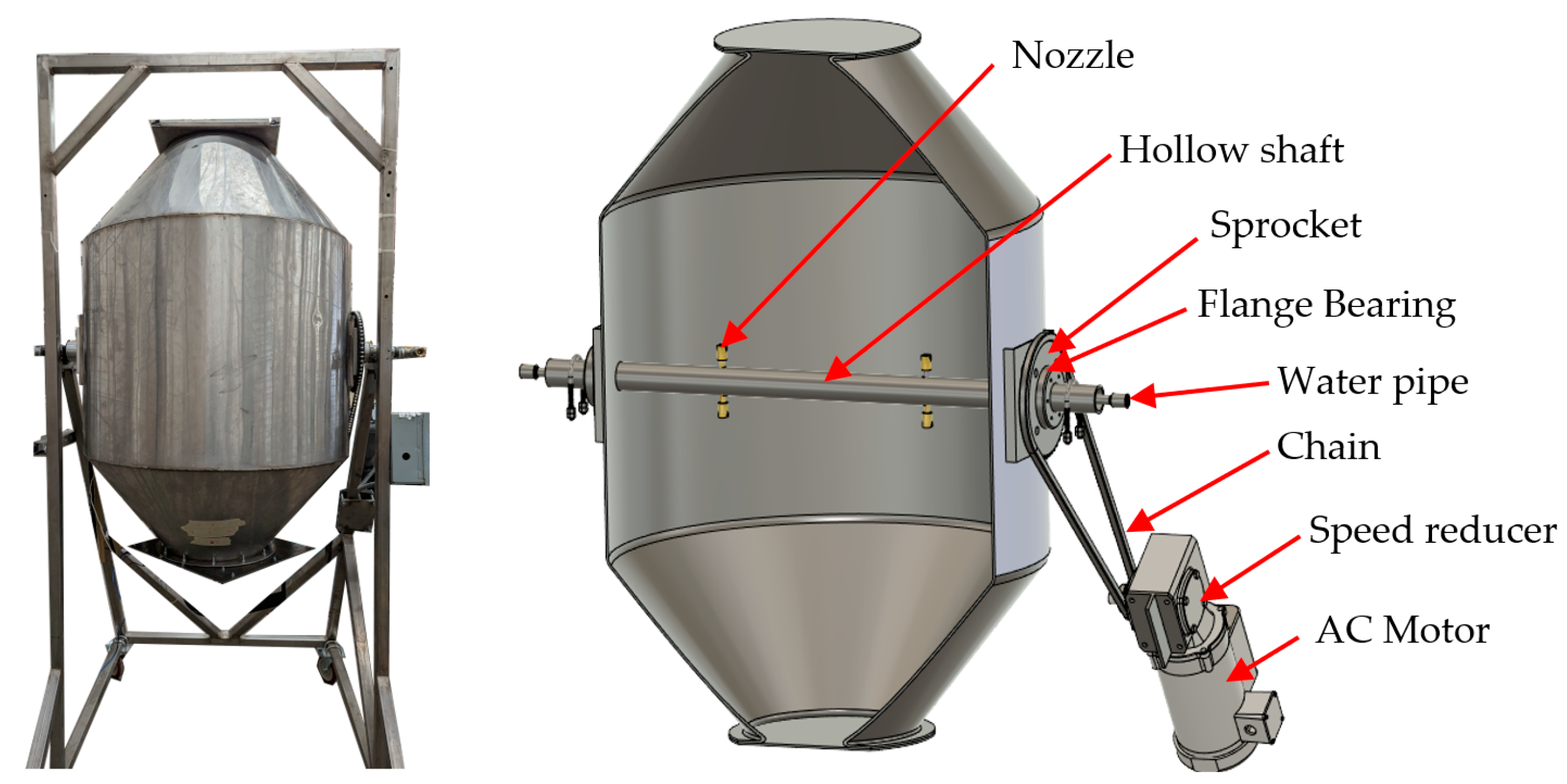
2.2.1. Vacuum Steam Pasteurizer

An existing batch-type 200L GMC (Figure 2) designed to increase and stabilize grain moisture content was modified into a vacuum steam pasteurizer. It has a conical-shaped conditioning chamber of 304 stainless steel with a thickness of 3.3 mm and a diameter of 821 mm. The chamber can be opened at the top or bottom for loading and unloading the grains. The chamber is supported by two plastic flange bearings connected to a 304 stainless-steel hollow shaft with outside and inside diameters of 38.1 mm and 25.4 mm, respectively, running across the chamber diameter. The hollow shaft is secured by a U-bolt to the 302 stainless-steel frame, elevating the chamber 1.5 m from the ground. A right-angle DODGE TIGEAR speed reducer (Reliance Electric Industrial Corporation, Greenville, SC, USA) with a speed ratio of 35:1, input power of 0.22 kW, and rotational speed of 1750 rpm, which is bolted on the right side of the frame, is connected to a 0.4 kW Dayton capacitor start motor with a 1725 rpm rotational speed to rotate the chamber. A 60-tooth sprocket is bolted to the flange bearing connecting the chamber to the speed reducer. An 11-tooth sprocket is attached to the output shaft of the speed reducer. A chain of size 40 joins these two sprockets. The water system of the chamber is rooted inside the hollow shaft. Inside the hollow shaft runs a 9.5 mm stainless-steel water pipe connected to four 6.4 mm flat-fan brass nozzles inside the chamber. The nozzles are arranged at the top and bottom, with two nozzles on each side and spaced 200 mm apart in the center of the chamber (Figure 2).
Converting a GMC into a VSP system requires structural integrity evaluations of the conditioning chamber before further modification due to the distinct operating conditions of both systems. GMC typically operates at room temperature and atmospheric pressure, whereas VSP requires higher temperatures and a sub-atmospheric environment. It is crucial to determine beforehand whether the conditioning chamber can withstand the vacuum and pasteurizing temperatures. If needed, structural reinforcement can also be added to avoid any unforeseen failures in the chamber. This initial approach ensures that the chamber does not fail during pasteurization.

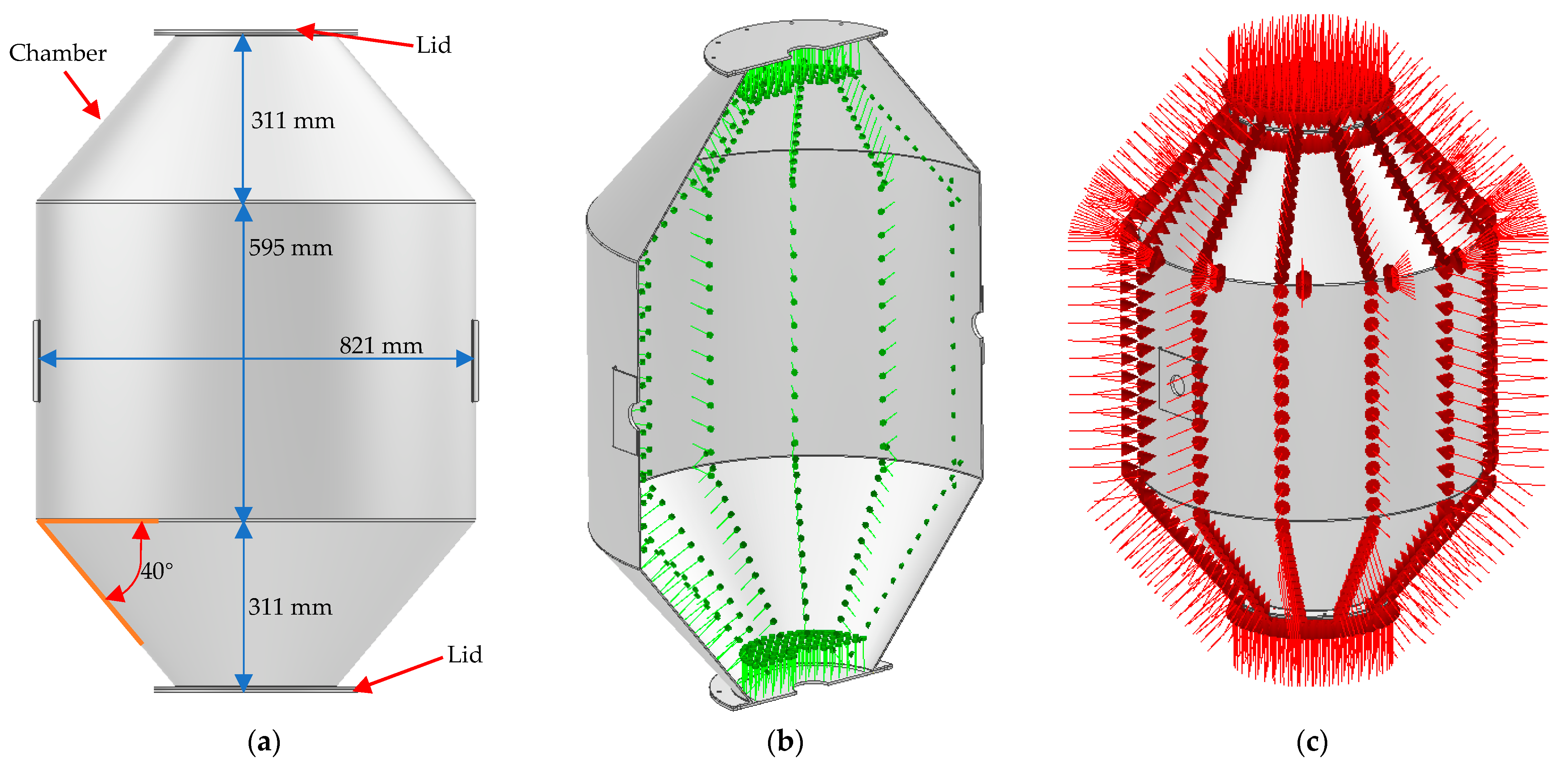
2.2.2. Structural Integrity of the Conditioning Chamber

In internal pressure vessel scenarios, the vessel remains intact if the hoop stress does not surpass the material’s yield strength. However, when under vacuum or external pressure, the vessel can fail in one of two ways [15]. If the vessel is short and has thin walls, it could fail when the stress in the walls reaches the material’s yield point. On the other hand, if the vessel is long and its walls are relatively thin, it could fail due to wall instability or buckling, even at stress levels well below the yield point. Validating the durability of the conditioning chamber under external pressure and high temperature is a quite complex issue. Computer-aided engineering (CAE) software is usually employed to simulate whether the conditioning chamber fails under buckling or not.
Using the computer-aided design (CAD) Fusion 360 software (Autodesk, San Francisco, CA, USA) [16] the chamber 3D model was drawn with three bodies: the chamber and the two lid covers (Figure 3a). This chamber model was then imported into Autodesk Inventor Nastran 2024 [17], where two numerical simulation analyses were performed. First, thermal stress simulations were carried out in two steps. In the first step, thermal analysis was conducted by selecting the linear steady-state heat-transfer function. A material composed of 304 stainless steel was applied to the 3D model at an initial body temperature of 20 °C. The lid cover and chamber were bolted together, but bonded connections between the touching surfaces were applied in the simulation. A bonded connection was acceptable since the pressure load was acting on the outside surfaces of the chamber and lid cover (Figure 3c). The pressure on the outer surface of the lid pushed the lid cover against the chamber, eliminating tension on the bolts. No constraint was applied in the model since it was not required in this type of analysis. The mesh setting was set to a 1-inch element size and a parabolic element order. To mimic the steam inside the chamber, a 100 °C temperature load (green probes) was applied to the inner surfaces of the chamber and lid cover (Figure 3b). The temperature of 100 °C is higher than the expected pasteurizing temperature, but it serves as a safety factor.
In the second step, the effects of vacuum and steam temperature on the thermal stress of the chamber were studied. The setup of the thermal stress analysis was the same as for the thermal analysis, but the linear steady-state heat-transfer function was changed to the linear static thermal stress function. An inertial relief constraint was applied in the model with the same mesh setting and element order as in the thermal analysis. The convergence setting was set to a local refinement with a maximum of 10 refinements, a convergence criterion of 5%, a refinement threshold of 0.9, and a refinement factor of 1.5. The result of the thermal analysis was used as a thermal-effect load in the thermal stress analysis, and an external pressure of 101.3 kPa (red arrows) was applied to the external surfaces of the chamber to imitate a perfect vacuum inside the chamber (Figure 3c). The buckling simulations address the issues raised by Windenburg and Trilling [15], who stated that a vessel exposed to external pressure can fail in buckling even if the actual stress does not reach the yield point of the material. The buckling simulations used the buckling function, where the setup, constraint, mesh setting, convergence setting, and loads were performed similarly to the thermal stress analysis (Figure 3c). The goal was to find the minimum external pressure the chamber would experience before buckling.
Finally, ASME Section VIII Division I guidelines were used to check the maximum allowable external pressure for the chamber to hold [18]. The chamber operates below 150 °C, and the external pressure should be less than the allowable pressure calculated using Equation (1). Where ( P a l l o w a b l e ) is the allowable external pressure the chamber should experience in [Pa], ( A ) is the equivalent strain from ASME Section II (0.000338), ( E ) is the modulus of elasticity of the 304 stainless steel (195 GPa), ( D o ) is the outside diameter of the chamber (821 mm), and ( t ) is the thickness of the chamber, which is 3.3 mm.
p a l l o w a b l e = 2 A E 3 D o t

2.3. Assessment of the GMC

2.3.1. Identification of Components for Modification

A visual inspection of the GMC was conducted to pinpoint components for modification, such as identifying and understanding the functions of critical parts like the water injection nozzles, water pipes, hollow shaft, bearings, conditioning chamber, mixing system, and structural frame. Second, the GMC was disassembled for a detailed study. Each component was measured using a Vernier absolute scale digital caliper, model 500-196-30, (Mitutoyo, Aurora, IL, USA) and tape measure (Stanley 33-735 Fatmax Tape Rule, Edmonton, AB, Cananda). These measurements were used to create a 3D model of the GMC using Fusion 360. The flange-bearing water system, including the pipes, hollow shaft, and water inlet port, were selected for modification. A preheater needed to be designed since the GMC does not have this feature. The existing mixing mechanism was left without any modification. Also, structural analysis of the frame was not considered since it had already proved to be able to withstand the loading (grains) during processing and, in addition, the frame was not exposed to heat from the steam.

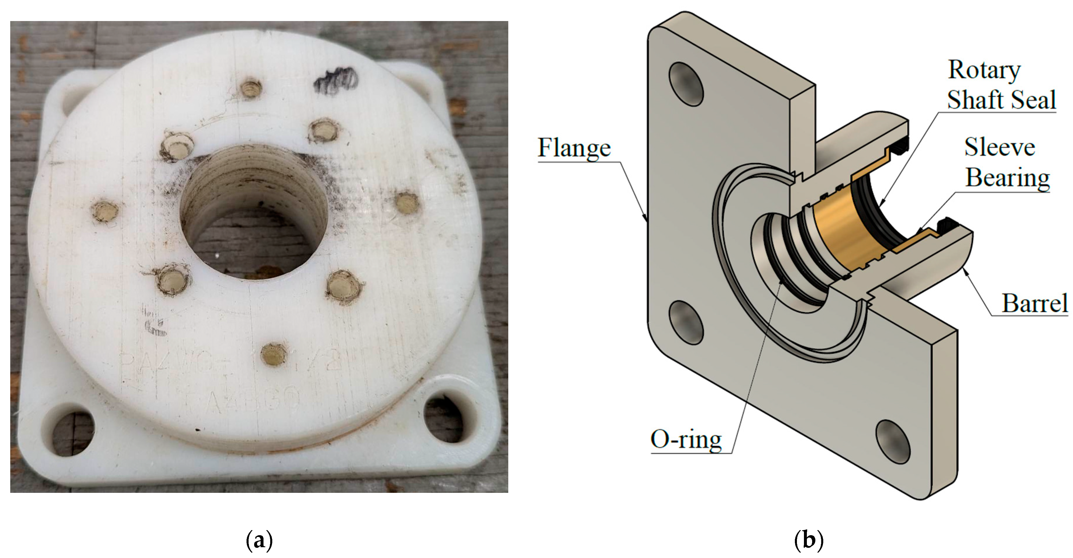
2.3.2. Modification Process

The GMC was successfully turned into a VSP system in four modification steps. The first step was to make the GMC conditioning chamber fully sealed. Sealing the chamber is necessary because VSP requires a vacuum environment, whereas GMC operates at atmospheric pressure. The chamber rotates to mix the grain, creating a challenge to make airtight the joints between the chamber and shaft to keep the vacuum condition inside the chamber. The hollow shaft and the chamber are connected by a 139 mm by 139 mm plastic flange bearing with a 38.1 mm diameter hole (Figure 4a) that is not designed to have an airtight gap between the hollow shafts. To make the connection airtight, a special flange with seals was necessary. This type of flange bearing is not readily available in the market. Therefore, a custom flange bearing was designed and 3D printed (Figure 4b).
The custom-designed flange bearing had three Buna-N rubber O-rings of 37.8 mm inside diameter, a brass flange sleeve bearing of 38.1 mm inside diameter, and a 38.1 mm spring-loaded rotary seal with a wiper lip. The prototype was made of 3D-printed ABS plastic. In the initial phase, the ABS plastic worked as intended, but later, cracks developed in layers where the materials had been deposited. The issue was resolved by changing into a 6061 aluminum flange bearing. The aluminum flange bearing was composed of two parts instead of one whole aluminum piece to save on material and machining costs. The flange had a dimension of 139 mm by 139 mm by 12.7 mm, while the nipple had a length of 58 mm with inside and outside diameters of 38.5 mm and 64 mm, respectively. The flanges and nipple were joined together using a 0.07 mm interference fit with the addition of high-temperature, high-strength Loctite. The custom flange bearing was attached to the chamber using four bolts; between the chamber and the flange bearing, a high-temperature O-ring was placed to make the connection airtight.
The hollow shaft was converted into a steam line by adding a vacuum and cooling line in the second step. The GMC water-injection system employs a nozzle linked to an internal pipe inside the hollow shaft for water-mist generation. The injected steam exists in a gaseous state. Therefore, the tube and nozzle were removed to convert the hollow shaft into a steam line. The diameter of the chamber is 821 mm, and the hole on each side of the hollow shaft is 200 mm away from the wall of the chamber. A 400 mm space is created between the holes, which means that all the steam is concentrated at the wall of the chamber. Using Autodesk CFD 2024 [19], the steam path was simulated, the hole’s locations were adjusted, and four additional holes were added to optimize the steam distribution inside the chamber. The existing holes of the hollow shaft were patched, and eight new holes with a diameter of 10 mm were drilled: four at the bottom and four at the top, with a 200 mm space between the centers of the holes (Figure 5).
The end of the hollow shaft on the left and right sides were modified to accommodate the steam, vacuum, preheater, and cooling line. A 25.4 mm by 19.1 mm galvanized iron (G.I.) bell reducer was welded onto both ends to allow easy connection of the G.I. nipple.
On the left-side end of the hollow shaft, a 19.1 mm G.I. nipple was connected to the bell reducer, followed by a 19.1 mm G.I. Tee fitting and 19.1 mm G.I. cross-connector fitting. All remaining connections on the Tee fitting and cross-connector had a 19.1 mm G.I. nipple followed by a 19.1 mm on/off brass valve, except on the top connection of the cross-fitting, where the vacuum gauge was installed. The on/off valve connects the preheater, the low-flow high-pressure vacuum, and cooling air. On the right-side end of the hollow shaft, a 19.1 mm G.I. nipple was connected to the bell reducer, followed by a 19.1 mm G.I. cross-connector fitting. All three connections on the cross-connector had a 19.1 mm G.I. nipple and a 19.1 mm on/off brass valve. The steam line, high-flow, low-pressure vacuum, and steam-trap drains were individually linked to its dedicated on/off valve.
The third step in the modification was to make an exhaust for the air heater during preheating. Adding an exhaust prevents the buildup of positive pressure inside the chamber and allows cool air to exit the chamber when hot air is injected. To achieve this, the chamber’s top and bottom lid covers were drilled to create a hole of 47.6 mm. A stainless-steel through-wall (thru-wall) connector with 25.4 mm sized pipes was installed at the hole, and a removable threaded plug was used to cover the through-wall connector to seal the chamber during vacuum operation (Figure 6). A high-temperature gasket was squeezed between the lid cover and the through-wall connector to make it airtight. The lid was bolted to the chamber, and a high-temperature gasket was placed between the touching surface of the lid and the chamber to create an airtight connection.
The final modification step was to cover the chamber with insulation material to reduce energy losses. The chamber is made of 3.33 mm thick 304 stainless steel with a thermal conductivity of 16.2 W/m-K. Using Fourier’s Law; the chamber overall heat-transfer coefficient (U-value) is approximately 4864 W/m2-K of energy when not insulated. Insulating the outer surfaces of the chamber reduces the heat loss. The external surfaces of the chamber were covered with a 12.7 mm flexible insulation material called NOMACO Insulation from Tarboro, NC, USA. This insulation material used has an estimated U-value or heat loss of 1.3 W/m2-K to 1.4 W/m2-K [20]. To calculate the thickness of the insulator, a U-value of 1.4 W/m2-K was used. The heat resistance (R-value) is the inverse of the U-value. Hence, taking the inverse of 1.4 W/m2-K, the heat resistance of the insulation is 0.7 (m2 × K/W). Since the insulator has a thermal conductivity of 0.018 W/m-K [20], the thickness of the insulator was calculated by multiplying the insulator’s thermal conductivity and heat resistance.

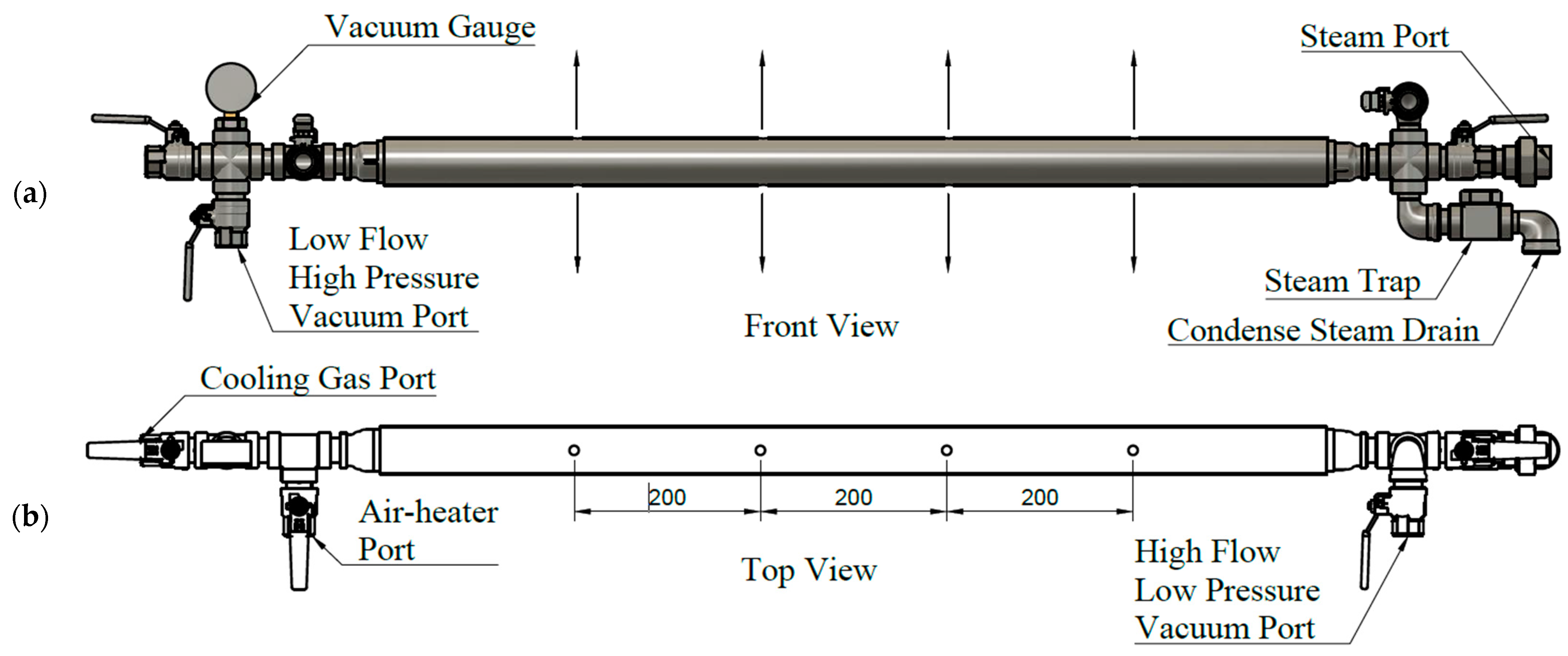
2.3.3. Air-Heater Design and Fabrication

The air-heater’s design target was to heat 50 kg of grain from an initial temperature ( T i w ) of 20 °C to a final temperature ( T f w ) of 40 °C, with a constant heated-air temperature ( T a ) of 100 °C at an injection velocity of 6 m/s. To ease the determination of the convective heat-transfer coefficient between the wheat and the heated air, the wheat shape was considered spherical even though its actual shape was oval. Equation (2), derived from Datta [2], was used to estimate the power ( P ) needed to elevate the temperature of the wheat from 20 °C to 45 °C. The Reynolds ( R e ) and Prandtl ( P r ) numbers were calculated from the air velocity, density, and viscosity, and by using the diameter ( D ) value of a single wheat grain. The thermal conductivity ( k ) and specific heat capacity ( c ) are the thermal properties of air. The estimated total surface area (A) of the wheat was calculated based on the estimated total amount of wheat present on the 50 kg of wheat multiplied by the surface area of one wheat grain. The time ( t ) was calculated from Fourier’s number from the Heisler chart [2].
P = 2 + 0.4 R e 0.5 + 0.06 R e ( 2 / 3 ) P r 0.4 k A c 2 T a T i w T f w 2 D t
The calculated total mass of air and power was used to choose an appropriate air heat gun. However, the default operation of air heat guns, which employ a fan to direct air into a heating coil, is not ideal for the VSP system due to the back pressure created by the grains in the pasteurizing chamber. To overcome this issue, the heating coils were extracted from the air heat gun and installed into a custom-built casing (Figure 7). The casing employs a forced-air mechanism driven by an air compressor, effectively dealing with the back-pressure issue. The casing was made from readily available G.I. pipe fittings. The core that houses the coils was made from a G.I. pipe nipple with a length of 152.2 mm and a diameter of 50.8 mm. At the intake and exhaust side of the core, a 50.8 mm by 38.1 mm G.I. bell reducer and a 38.1 mm to 19.1 mm bush adapter were installed.
During the preheating process, pressurized air was injected into the intake side of the preheater. The air expands before entering the heating coil, lowering its pressure and temperature. This condition created a problem because it allowed the moisture present in the pressurized air to condense back into water. To address this problem, stainless steel Scotch-Brite pads were installed on the intake-side bell reducer to trap the condensed water. A hole of 3 mm was drilled on the bell reducer to serve as a drain outlet for the condensed water.

2.3.4. Experimental Setup

The pasteurizing chamber has a volume capacity of 0.48 m3; however, the recommended usable volume is 0.2 m3, which is 40% of the total volume equivalent to a wheat capacity of 150 kg. However, the study used 50 kg of wheat, occupying 0.07 m3 of the chamber, which is 15% of the volume of the chamber. A load of 50 kg of wheat kernels was added into the chamber, and then the AC motor was switched on to rotate the chamber continuously at 9 rpm per minute. The wheat kernels were preheated to increase the wheat temperature to 40 ± 4 °C. The North Dakota State University Pilot Plant Service Center’s in-house low-pressure, high-flow vacuum pump accelerated the vacuum process from an atmospheric pressure of 101.3 kPa to 46.2 kPa. To push the pressure further to 11.7 kPa, a rotary vane 117 vacuum pump (Labconco, Kansas City, MO, USA) was employed. After the vacuum reached 11.7 kPa, it was turned off, and steam was injected inside the chamber until it reached 85 °C.
To monitor the vacuum inside the pasteurizing chamber, an Omega pressure transducer (model PX319-030AI) was used that has a pressure range of 0 kPa to 345 kPa, electrical output of 0 to 10 Vdc, operating temperature of −40 °C to 85 °C, and response time of <1 ms. It was mounted at the chamber’s top lid cover (Figure 8a), and pressure transducer readings were collected at a 0.2 Hz data sampling rate. Upon achieving an 11.7 kPa absolute pressure, steam was injected into the pasteurizing chamber via an Amerec AI Commercial Steam Boiler (model AI-12). To measure the temperature inside the chamber, K-type thermocouples were used. The thermocouples have a temperature range of −200 °C to 1260 °C, an accuracy of ±2.2 °C, and a response time of 500 ms. Seven thermocouples were installed within the pasteurizing chamber to measure the temperature at a sampling frequency of 0.2 Hz (Figure 8b). A wireless data acquisition unit, LabJack T7-Pro, with 24-bit resolution, was used to collect the pressure and temperature readings. The LabJack T7-Pro can only accommodate four sensors, but with a CB37 terminal board, the capacity was increased to eight. The steam was turned off once the chamber’s internal temperature attained 84 ± 1 °C. The steam inside the chamber was held for 1 min before activating the vacuum pump to remove the steam swiftly. After the pressure inside the chamber was lowered to 11.7 kPa, cool air was injected to reduce the grain temperature rapidly.

3. Results and Discussion

3.1. Numerical Simulation

3.1.1. Chamber Structural Integrity

The vacuum serves as an external pressure load on the pasteurizing chamber that can lead the chamber to fail. When the chamber is in a perfect vacuum, the atmospheric pressure (101.3 kPa) pushes the outer surfaces inward, which can cause the chamber to implode. The failure occurs when the chamber’s material, 304 stainless steel, cannot bear the stress generated by the atmospheric pressure. Also, with the addition of heat, the chamber’s strength is further reduced. Therefore, the GMC chamber was analyzed to see if it could withstand the 101.3 kPa (perfect vacuum) pressure at 100 °C. Figure 9a shows the heat distribution of the thermal analysis on the vessel. When the inner surface of the chamber was exposed to 100 °C, the heat was absorbed throughout the body until the body temperature equalized the 100 °C heat source. This absorbed heat changes the strength of the 304 stainless steel. At room temperature, the yield strength of the 304 stainless steel was 245 MPa, but when heated to 100 °C, the yield strength was reduced to 195 MPa [21]. The 195 MPa yield strength of the 304 stainless steel was used to determine the chamber’s safety factor against the working temperature and external pressure load. The chamber’s minimum safety factor was calculated by dividing the yield strength (195 MPa) and the equivalent stress of 81.95 MPa (Figure 9b). Based on the calculated safety factor, the chamber can withstand an external pressure of 202.6 kPa, which is twice the atmospheric pressure limit. The simulation result was consistent with the maximum allowable external pressure (199.6 kPa) that was calculated using the ASME simplified calculations for an external pressure vessel [19].
Figure 9c shows the buckling analysis that was performed. The chamber will collapse when the middle section of the chamber is deformed into a similar shape at a displacement of 25 mm in mode 1 and a 10.42 eigenvalue (buckling load multiplier) [15]. Multiplying 10.42 with the applied 101.3 kPa of external pressure will result in 1.1 MPa. This 1.1 MPa pressure is the minimum external pressure that will make the chamber fail in buckling. This pressure is over 10 times higher than the expected 101.3 kPa external pressure. The result of the buckling analysis proves that the chamber will not fail during the regular operation. Therefore, the chamber was proven safe to operate as a pasteurizing chamber without needing modification to make it durable enough to withstand the 101.325 kPa external pressure in a perfect vacuum at the 100 °C pasteurizing temperature.

3.1.2. Steam Distribution

Consistent steam distribution is essential for various food processing tasks, such as drying, cooking, and pasteurization. Therefore, ensuring uniform steam distribution within the pasteurizing chamber is crucial to guaranteeing that each wheat grain is equally exposed to the heat. The initial steam line featured four outlets (two on each side). Simulation of the system with four steam outlets on Autodesk CFD demonstrated a non-uniform steam concentration toward the chamber’s sides, as demonstrated by the blue lines (steam-path flow) in Figure 10a. On the other hand, adding four steam outlets, making a total of eight outlets, greatly enhanced the steam-path distribution and made the steam distribution more uniform within the chamber, as shown in Figure 10b.

3.2. Experimental Results

3.2.1. Vacuum Assessment

When implementing a vacuum in the pasteurizing chamber, a key consideration is the interface between the stationary steam injector that serves as the shaft and the rotating pasteurizing chamber. Introducing a custom flange bearing equipped with a sealing mechanism addresses this issue, creating a vacuum inside the chamber. To test the vacuum capacity of the chamber while rotating, an in-house low-pressure, high-volume-flow vacuum system was used to rapidly decrease the atmospheric pressure from 101.3 kPa to 46.2 kPa within 4 min (Figure 11). Following this, a high-vacuum, low-volume-flow vacuum pump was used for an additional 6 min to lower the pressure further to 11.7 kPa, passing the desired 32.4 kPa absolute pressure specified by [7,8]. Using only the high-vacuum, low-volume-flow vacuum pump would have significantly increased the time needed to achieve the required pressure. Hence, the two-step process was effective in providing the required pressure in 10 min. At 10 min, no additional vacuum was introduced; instead, the chamber was continuously rotating until it reached 23 min. Then, the vacuum was released, allowing the chamber pressure to equalize to the atmospheric pressure. As seen in the figure, maintaining the vacuum from 10 min to 23 min while rotating the chamber at 9 rpm resulted in a 344 Pa pressure increase per minute. From this result, the vacuum pressure can be held for more than 10 min, which would satisfy the 9 min pasteurizing time [8]. Even at 23 min, the vacuum pressure was above the target pressure. This creates enough excess pressure to absorb the positive pressure from a steam injection, and the system will still operate at the required vacuum pressure.

3.2.2. Heat Distribution

Subsequently, heat distribution tests were carried out using seven K-type thermocouples inside the chamber. This test was used to validate the steam distribution from the simulation. The sensor readings shown in Figure 12 demonstrate that the heat distribution inside the chamber was fairly distributed. This experiment was performed with 50 kg of wheat, with no vacuum and no preheating. The first temperature reading in the first 12 min was stable at 28 ± 0.9 °C. Once steam was injected into the chamber, the temperature increased to 70.71 ± 1.90 °C. Considering the thermocouple’s accuracy margin of ±2.2 °C, the inside temperature of the chamber displays a maximum temperature variation of 4 °C. This discrepancy is small and can be neglected because the chamber rotates during grain pasteurization, ensuring sufficient exposure to steam. Therefore, adding four more holes in the steam line improves the heat distribution inside the chamber. Also, a single temperature sensor will be adequate to monitor internal chamber temperatures.

3.2.3. Preheating Strategy

To optimize the VSP process, the product should preheat the samples from room temperature to 15–35 °C below the target pasteurization temperature [10]. Then, the injected steam brings the product’s surface temperature to the target temperature. Preheating is usually done using hot air, which helps to avoid the condensation issues that would have been caused if steam was used for preheating. By increasing the product temperature to at least 40–50 °C before steam injection, the preheater reduces the temperature difference between the steam and the pasteurizing products, which mitigates steam condensation and ensures a more efficient pasteurization process. Temperature regulation and steam distribution play critical roles in achieving successful pasteurization. For instance, when pasteurizing wheat arranged in a static sphere, the grains at the core require more time before they are exposed to steam, as steam penetration takes time. To overcome this, VSP incorporates a mixing mechanism of the GMC system that slowly rotates the chamber at 9 rpm. This keeps the grains in motion, ensuring that all grains are immediately exposed to the steam and significantly reducing the penetration time.
Additionally, the rate of heating the chamber was strongly correlated with the existence of insulation around the chamber. Figure 13 shows the temperature profile of the chamber with and without an insulator. At an ambient temperature of 20 °C without insulation in the chamber’s outer surfaces, the preheater needs 110 min to heat a 50 kg wheat kernel to 42 °C. This was due to the fact there was heat loss through the highly thermal-conductive stainless-steel walls. However, the addition of insulation on the outer surfaces of the chamber significantly shortened it from 110 min to 15 min.

3.2.4. A Modified VSP System and Its Operational Procedure

The purpose of the apparatus is to mimic the pasteurization process conditions of the VSP system from previous lab-scale experiments conducted on LMFs like wheat, flaxseed, and peppercorn [6,7,8,9,10] in a larger sample volume. These conditions include preheating the product to >40 °C, lowering the chamber pressure to 32.4 kPa absolute pressure, injecting steam to reach a temperature of 65 °C to 85 °C for 1 to 8 min, and, finally, removing steam through a vacuum. Figure 14 shows the modified VSP apparatus. It has a preheater, a low-flow, high-vacuum pump, an in-house high-flow, low-pressure vacuum pump, and a steam boiler. Compared with the laboratory scale setup with a sample capacity of less than 1 kg, the modified VSP system has a total volume of 0.48 m3 and can accommodate a maximum of 150 kg of grains. It also has a mixing mechanism to ensure uniform exposure of grains to the steam. The laboratory scale setup has a small chamber volume, making it easy to evacuate the steam rapidly. A high-flow, low-vacuum pump was used to attain similarly rapid steam evacuation of the steam in the larger VSP system. Another laboratory setup uses a separate forced-air drying oven to preheat the product. In the modified equipment, the preheater is integrated, hence eliminating the need for separate preheating equipment.
The VSP system adopts a batch processing method. Its operation is a sequence of grain loading, preheating, vacuum initiation, steam injection, steam holding, and steam evacuation (via vacuum), followed by simultaneous vacuum release and grain cooling. The 50 kg wheat kernels underwent preheating for 22 min to reach 45 °C (Figure 15). After reaching 45 °C, the heater was turned off and the exhaust was covered using a threaded plug to ensure that the vacuum pressure was maintained. Then the vacuum pump was activated for 10 min to lower the chamber pressure from 101.3 kPa to 12 kPa. During the vacuum depressurization, the temperature of the wheat dropped from 45 °C to 42 °C. This temperature drop was expected since the air inside the chamber was being removed. Upon reaching a pressure of 12 kPa, the vacuum pump was deactivated, and steam was injected into the chamber for 6 min, elevating the wheat temperature to 85 °C.
Upon reaching 85 °C, the steam boiler was turned off, and the steam inside the chamber was held for only 1 min. It has been shown that prolonged wheat exposure at this temperature alters some of its properties [8]. Also, the absolute pressure inside the chamber increased to 74 kPa during steam injection. This is expected as steam has positive pressure; hence, it was important to have a unit that can hold high vacuum pressure. After 1 min of steam-holding time, the vacuum pump was activated for 8 min, lowering the chamber pressure to 12 kPa. During the 8 min vacuum activation, the steam was also simultaneously removed, preventing additional condensation of the steam. In this operation section, the wheat temperature also dropped from 85 °C to 74 °C. The cycle concludes with the simultaneous release of the vacuum and the introduction of cool air, thereby lowering the wheat temperature to 30 °C, ensuring a minimal effect of heat on the wheat quality. The chamber was mixed thoroughly throughout the process.

4. Conclusions

The repurposed GMC demonstrates successful modification and conversion into a VSP system.
  • The chamber’s structural analysis illustrates its substantial resistance to external pressures. Thermal stress and buckling analyses confirm the chamber’s integrity and safety under operational conditions of 11.7 kPa absolute pressure and temperature values between 85 °C to 100 °C, effectively addressing structural failure concerns.
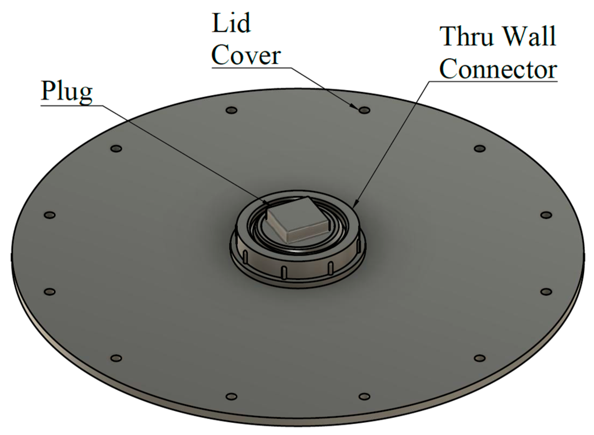
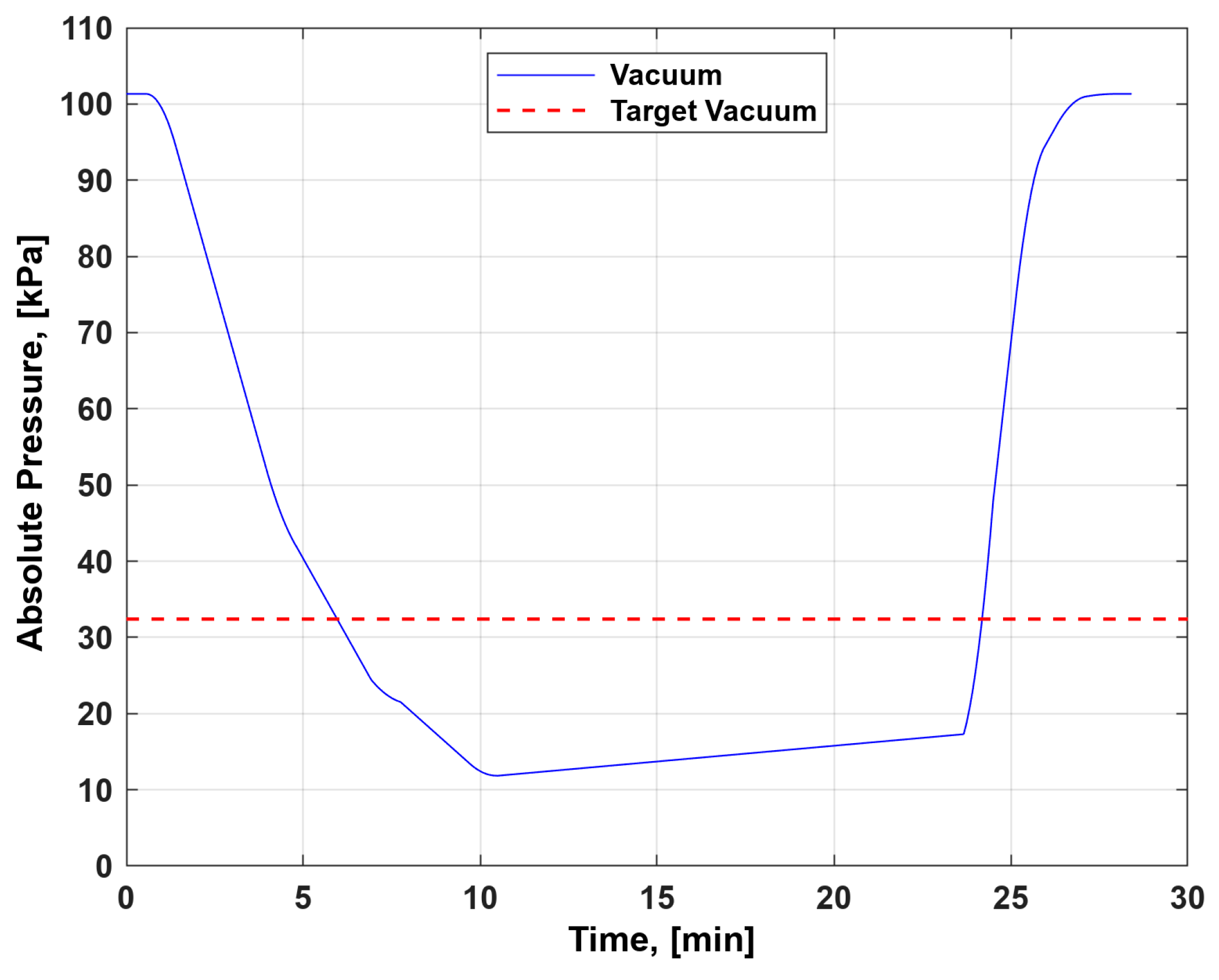
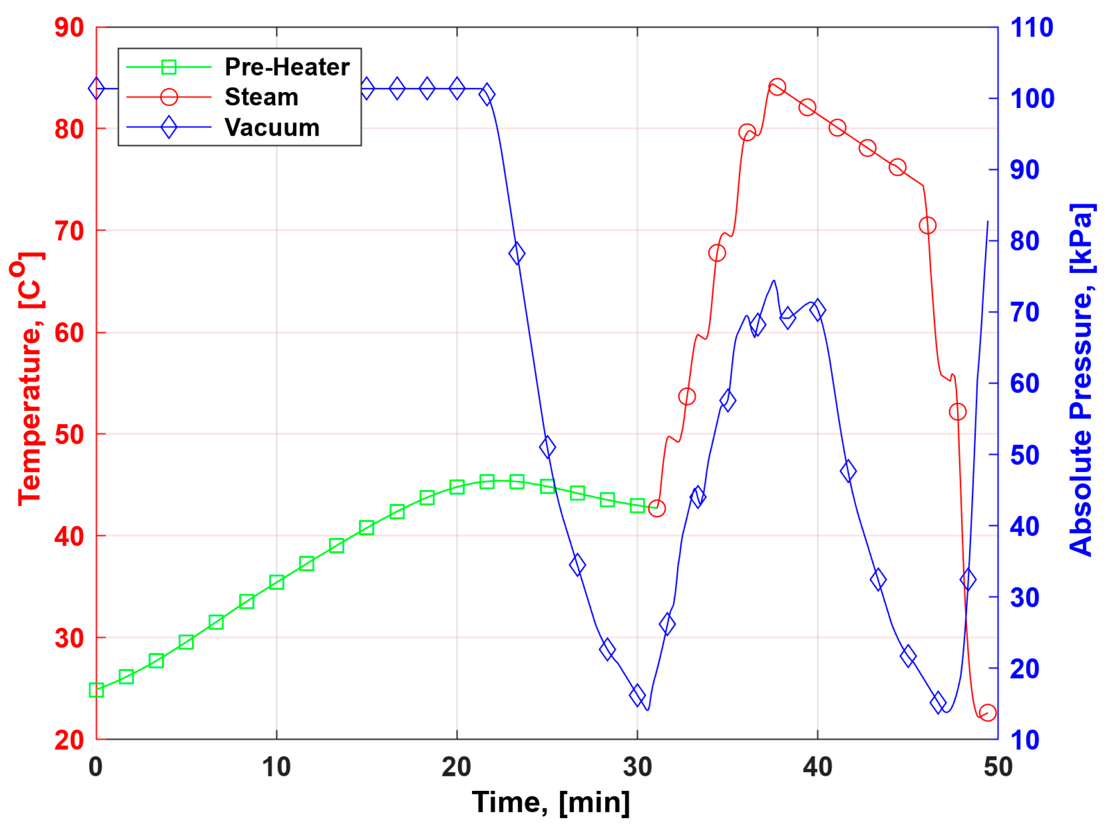
  • The vacuum capability has been deftly addressed. Introducing a custom flange bearing with a seal seals the joint between the stationary shaft and the rotating chamber. This design innovation ensures that the chamber can sustain an absolute pressure of 11.7 kPa for durations of 10 min at a pressure increase of 344 Pa per minute.
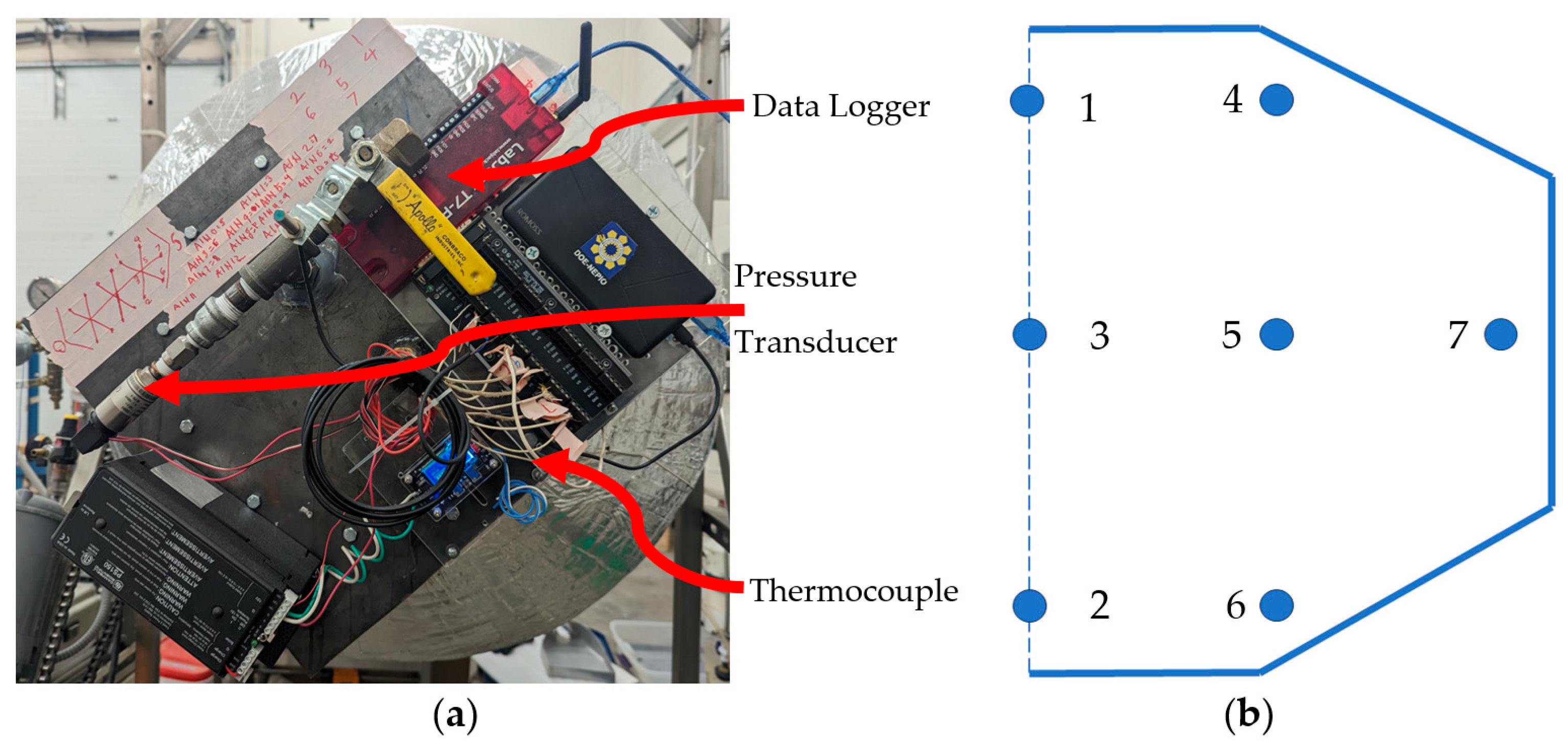
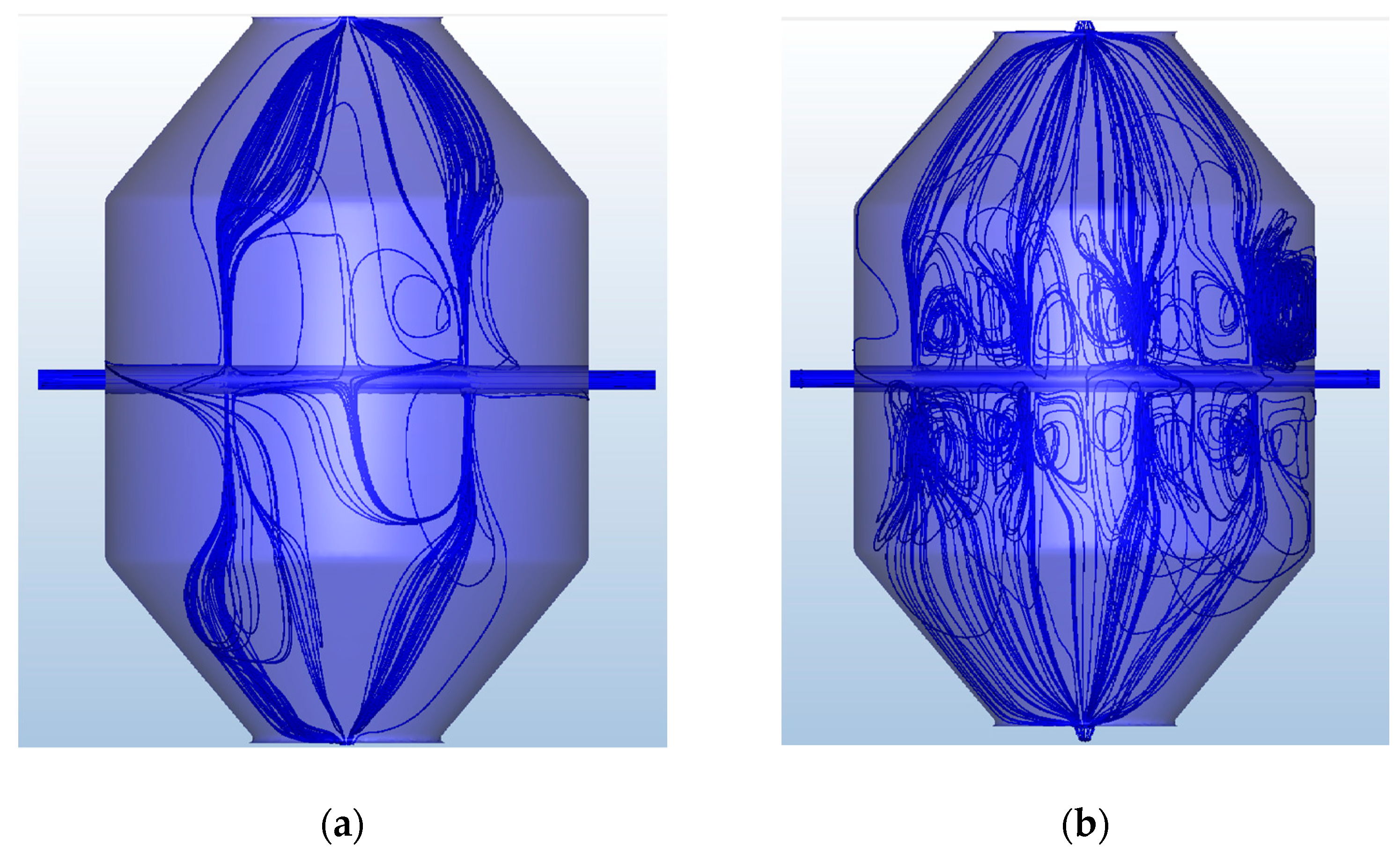
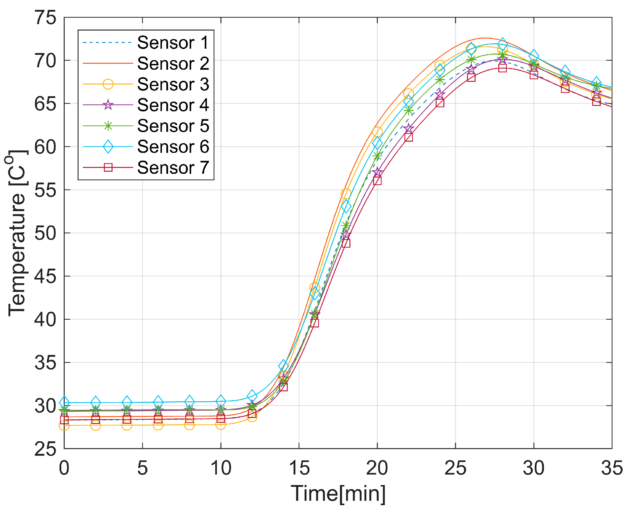
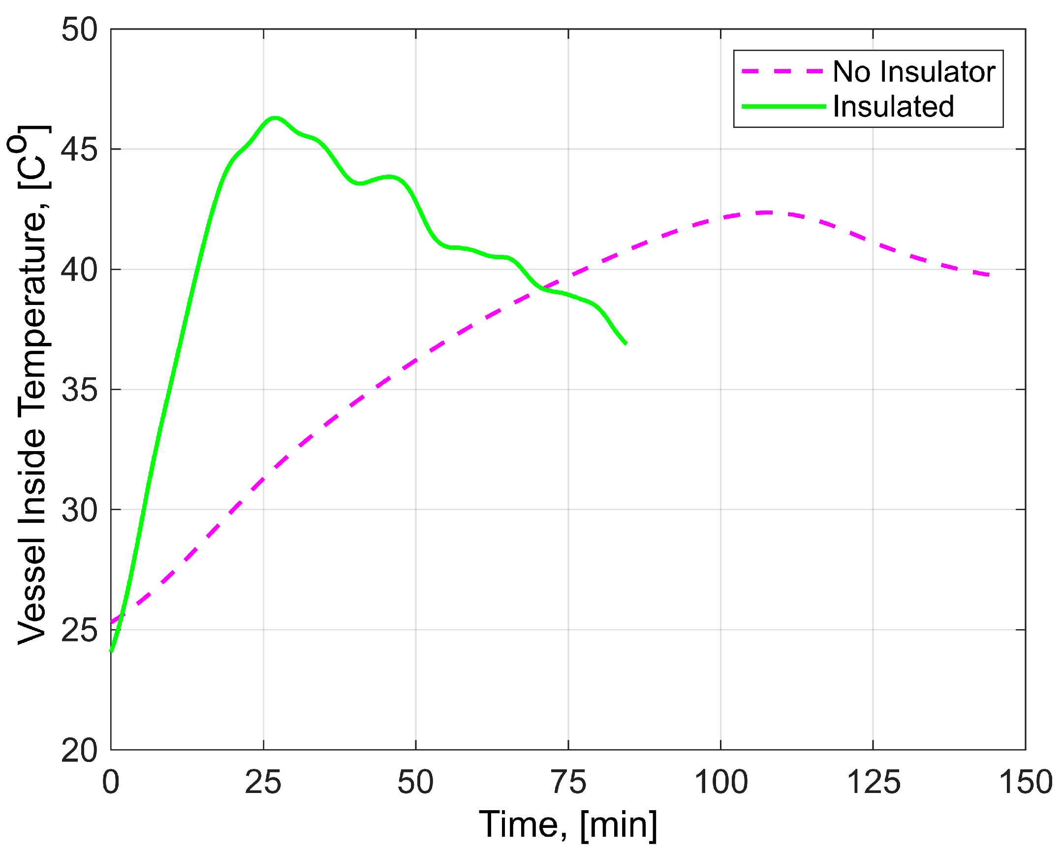
  • Heat distribution, an imperative condition for any pasteurization procedure, showed room for improvement in initial configurations. With the introduction of additional holes, there was a noticeable improvement in steam distribution. Actual measurements with K-type thermocouples further supported this, which showcased minimal temperature variances inside the chamber, suggesting that a singular temperature sensor is sufficient for internal temperature monitoring. A key challenge was the direct steam injection, which posed moisture concerns due to temperature disparities between the steam and the grains. Incorporating a preheater, complemented by adding insulation, addressed this challenge, ensuring an optimal pre-pasteurization temperature for grains and shortening the preheating time from 110 min to 15 min.
Testing the process conditions of the modified VSP system with 50 kg of wheat showed that the system can be successfully used to replicate the process conditions of laboratory-scale setups, bridging the gap between small-scale experiments and larger, more commercial applications.
Future research utilizing this apparatus will primarily focus on assessing and enhancing the microbial reduction efficiency toward LMFs, with the goal of fine-tuning the pasteurization process for maximum efficiency while maintaining the quality of the grains, thus making this technology a viable option for large-scale grain pasteurization in the industry.

Author Contributions

M.G.: writing—original draft, review and editing, investigation, software, validation, formal data analysis, and data visualization. S.E.: conceptualization, methodology, investigation, and writing—review and editing. E.M.: conceptualization, methodology, investigation, and writing—review and editing. All authors have read and agreed to the published version of the manuscript.

Funding

North Dakota Agricultural Experiment Station (FARG007277) and USDA-NIFA Hatch multistate ND01491 for funding the research. The Department of Science and Technology, Engineering Research for Technology (DOST-ERDT), Philippines, for funding MG’s tuition and stipend.

Data Availability Statement

The data will be provided upon request.

Conflicts of Interest

The authors declare that they have no known competing financial interests or personal relationships that could have appeared to influence the work reported in this paper.

Abbreviations

LMFsLow-moisture foods
VSPVacuum Steam pasteurization
GMCGrain Moisture Conditioner
CDCCenter for Diseases Control
FDAFood and Drug Administration
FSMAFood Safety Modernization Act
E. coliEscherichia coli
CFUColony-forming unit
CAEComputer-aided engineering
CADComputer-aided drafting
ASMEAmerican Society of Mechanical Engineers
ABSAcrylonitrile butadiene styrene
CFDComputational fluid dynamics
G.I.Galvanized iron
msMilliseconds
rpmRevolutions per minute

References

  1. Strauss, D.M. An Analysis of the FDA Food Safety Modernization Act: Protection for Consumers and Boon for Business. Food Drug Law J. 2011, 66, 353–376. [Google Scholar] [PubMed]
  2. Datta, A.K. Biological and Bioenvironmental Heat and Mass Transfer; Marcel Dekker Inc.: New York, NY, USA, 2002. [Google Scholar]
  3. Kittiworrawatt, S.; Devahastin, S. Improvement of a mathematical model for low-pressure superheated steam drying of a biomaterial. Chem. Eng. Sci. 2009, 64, 2644–2650. [Google Scholar] [CrossRef]
  4. Sánchez-Maldonado, A.F.; Lee, A.; Farber, J.M. Methods for the Control of Foodborne Pathogens in Low-Moisture Foods. Annu. Rev. Food Sci. Technol. 2018, 9, 177–208. [Google Scholar] [CrossRef] [PubMed]
  5. Newkirk, J.J.; Wu, J.; Acuff, J.C.; Caver, C.B.; Mallikarjunan, K.; Wiersema, B.D.; Williams, R.C.; Ponder, M.A. Inactivation of Salmonella enterica and Surrogate Enterococcus faecium on Whole Black Peppercorns and Cumin Seeds Using Vacuum Steam Pasteurization. Front. Sustain. Food Syst. 2018, 2, 48. [Google Scholar] [CrossRef]
  6. McEvoy, J.M.; Doherty, A.M.; Sheridan, J.J.; Blair, I.S.; McDowell, D.A. Use of steam condensing at subatmospheric pressures to reduce Escherichia coli O157:H7 numbers on bovine hide. J. Food Prot. 2001, 64, 1655–1660. [Google Scholar] [CrossRef] [PubMed]
  7. Simsek, S.; Snelling, J.; Malekmohammadi, S.; Bergholz, T.M. Vacuum steam treatment of soft wheat: Quality and reduction of Escherichia coli O121 and Salmonella Enteritidis PT30. Cereal Chem. 2021, 98, 123–134. [Google Scholar] [CrossRef]
  8. Snelling, J.; Malekmohammadi, S.; Bergholz, T.M.; Ohm, J.; Simsek, S. Effect of Vacuum Steam Treatment of Hard Red Spring Wheat on Flour Quality and Reduction of Escherichia coli O121 and Salmonella Enteritidis PT 30. J. Food Prot. 2020, 83, 836–843. [Google Scholar] [CrossRef] [PubMed]
  9. Hwang, S.H.; Joe, S.Y.; So, J.-H.; Lee, S.H. Development of Vacuum-Steam Combination Heating System for Pasteurization of Sprout Barley Powder. Foods 2022, 11, 3425. [Google Scholar] [CrossRef] [PubMed]
  10. Shah, M.; Eklund, B.; Conde Lima, L.G.; Bergholz, T.; Hall, C., III. Microbial and Chemical Shelf-Life of Vacuum Steam-Pasteurized Whole Flaxseed and Milled Flaxseed. J. Food Sci. 2018, 83, 300–308. [Google Scholar] [CrossRef]
  11. Flessner, M.L.; Burke, I.C.; Dille, J.A.; Everman, W.J.; VanGessel, M.J.; Tidemann, B.; Manuchehri, M.R.; Soltani, N.; Sikkema, P.H. Potential wheat yield loss due to weeds in the United States and Canada. Weed Technol. 2021, 35, 916–923. [Google Scholar] [CrossRef]
  12. Liu, S.; Roopesh, M.S.; Tang, J.; Wu, Q.; Qin, W. Recent development in low-moisture foods: Microbial safety and thermal process. Food Res. Int. 2022, 155, 111072. [Google Scholar] [CrossRef]
  13. Wason, S.; Verma, T.; Subbiah, J. Validation of process technologies for enhancing the safety of low-moisture foods: A review. Compr. Rev. Food Sci. Food Saf. 2021, 20, 4950–4992. [Google Scholar] [CrossRef]
  14. Stavropoulos, P.; Papacharalampopoulos, A.; Tzimanis, K.; Petrides, D.; Chryssolouris, G. On the Relationship between Circular and Innovation Approach to Economy. Sustainability 2021, 13, 11829. [Google Scholar] [CrossRef]
  15. Windenburg, D.F.; Trilling, C. Collapse by Instability of Thin Cylindrical Shells Under External Pressure. Trans. Am. Soc. Mech. Eng. 2023, 56, 819–825. [Google Scholar] [CrossRef]
  16. Verma, G. Autodesk Fusion 360 Black Book; BPB Publications: Delhi, India, 2018. [Google Scholar]
  17. Verma, G.; Samar. Basics of Autodesk Nastran In-CAD 2018; CADCAMCAE Works: Eastman, GA, USA, 2018. [Google Scholar]
  18. Vinayka, S. Simplified External Pressure Design of ASME Pressure Vessels Using Closed Form Solution. J. Press. Vessel Technol. 2020, 142, 054504. [Google Scholar] [CrossRef]
  19. Madej, J.; Będkowski, B. Air Flow Analysis for Electrical Motor’s Cooling System With Autodesk Simulation Cfd 2013 Program. Acta Mech. Autom. 2013, 7, 89–92. [Google Scholar] [CrossRef]
  20. Li, F.G.N.; Smith, A.Z.P.; Biddulph, P.; Hamilton, I.G.; Lowe, R.; Mavrogianni, A.; Oikonomou, E.; Raslan, R.; Stamp, S.; Stone, A.; et al. Solid-wall U-values: Heat flux measurements compared with standard assumptions. Build. Res. Inf. 2015, 43, 238–252. [Google Scholar] [CrossRef]
  21. Soares, G.C.; Rodrigues, M.C.M.; de Arruda Santos, L. Influence of Temperature on Mechanical Properties, Fracture Morphology and Strain Hardening Behavior of a 304 Stainless Steel. Mater. Res. 2017, 20, 141–151. [Google Scholar] [CrossRef]
Figure 1. Typical lab-scale vacuum steam pasteurizer.
Designs 08 00001 g001
Figure 2. Grain moisture conditioner before modification. The cross-sectional view showing the internal components of the conditioner.
Designs 08 00001 g002
Figure 3. Conditioning chamber: (a) Chamber 3D model; (b) Thermal analysis setup; (c) Thermal stress and buckling analysis setup. The arrows represent thermal and pressure stress.
Designs 08 00001 g003
Figure 4. Flange bearing: (a) Original flange bearing; (b) Custom flange bearing.
Designs 08 00001 g004
Figure 5. Modified hollow shaft for the steam, vacuum, and cooling line: (a) Front view; (b) Top view.
Designs 08 00001 g005
Figure 6. Design of a new chamber lid cover.
Designs 08 00001 g006
Figure 7. Design of an air heater for preheating.
Designs 08 00001 g007
Figure 8. Data collection: (a) Sensors and data logger setup, (b) Points in the chamber of the thermocouple position.
Designs 08 00001 g008
Figure 9. Thermal stress analysis of the chamber: (a) Heat distribution on the chamber walls; (b) Thermal stress on the chamber; and (c) Chamber buckling analysis.
Designs 08 00001 g009
Figure 10. Steam path and distribution with (a) four holes and (b) eight holes.
Designs 08 00001 g010
Figure 11. Vacuum inside the pasteurizing chamber.
Designs 08 00001 g011
Figure 12. Temperature inside the pasteurizing chamber.
Designs 08 00001 g012
Figure 13. Temperature progression in the pasteurizing chamber.
Designs 08 00001 g013
Figure 14. Modified VSP apparatus.
Designs 08 00001 g014
Figure 15. Preheater, vacuum, and steam interaction during operation.
Designs 08 00001 g015
Disclaimer/Publisher’s Note: The statements, opinions and data contained in all publications are solely those of the individual author(s) and contributor(s) and not of MDPI and/or the editor(s). MDPI and/or the editor(s) disclaim responsibility for any injury to people or property resulting from any ideas, methods, instructions or products referred to in the content.

