Abstract
In the realm of high-pressure vessel simulation, conventional finite element method (FEM) approaches, as per ASME standards, may inadequately predict the behavior of flat surfaces under elevated temperatures. This study challenges the efficacy of shell-type mesh modeling for high-temperature flat plates, demonstrating that the thermal conditions within such high-pressure vessels can induce thermal instability and buckling, not accounted for by traditional FEM methods recommended by ASME. Through comprehensive analytical investigations, we reveal that traditional shell-type meshing techniques, while suitable for certain applications, fail to capture the intricate thermal stresses and deformation patterns inherent in high-temperature flat plate configurations. Our analysis delineates distinct stability regimes governed by key design parameters, including plate thickness, operating temperature, and geometric dimensions, profoundly impacting the structural integrity of heating plates under thermal loading. Specifically, we found that increasing the plate thickness enhances resistance to thermal buckling, clamping the plate edges raises the critical buckling temperature, and selecting materials with lower thermal expansion coefficients improves stability. These findings provide engineers with critical insights necessary for optimizing the design and performance of high-temperature equipment. This includes the design of high-pressure vessels with flat surfaces for heating materials, flanges in high-temperature environments, and fins in heat exchangers across various industries such as oil and gas, pyrolysis, and power plants. The findings presented herein serve as a valuable reference for engineers seeking to comprehend and mitigate instability phenomena in solid mechanics, offering practical guidance for developing robust and reliable high-temperature structures in demanding industrial environments.
1. Introduction
Designing pressure vessels for heating purposes presents significant challenges, especially in high-temperature environments and where corrosive substances are present [1,2]. The growing demand for advanced thermal processing systems underscores the need for robust heating surfaces that can withstand extreme conditions [3,4]. These systems typically involve heat transfer fluid on one side and processed materials on the other, necessitating materials with both corrosion resistance and mechanical strength at elevated temperatures [5,6]. The presence of high-pressure fluids, combined with temperature gradients causing thermal expansion and resulting thermal stresses, further complicates the design. Additionally, ensuring corrosion resistance adds another layer of complexity to the configuration of heating surfaces [7,8].
In the conventional design of typical high-pressure vessels, which are commonly fabricated with curved bodies, the primary design consideration is often centered around the pressure exerted by the fluid contained within [9]. This assumption holds true for curved vessels where thermal expansion has minimal impact on the overall stress state, aligning well with ASTM recommendations that advocate for shell-type mesh in finite element method (FEM) analysis of such vessels [10]. However, a critical question arises when high-pressure vessels incorporate flat components or are entirely composed of flat plates: can the same recommendation guarantee a reliable safety factor under these conditions?
This scenario presents a real-world industry problem where a high-pressure vessel, constructed from two parallel circular hollow plates interconnected by pins, contained a heating fluid under 50 psi pressure (see Figure 1). Initially, the system was assumed to maintain uniform temperature. Finite element method (FEM) modeling, employing a shell-type mesh as recommended by ASME, suggested a safety factor of 2. However, several weeks into operation, symmetrical patterns indicative of plastic deformations appeared on the heating plates (see Figure 2). Despite initial assessments using FEM modeling to ensure structural integrity, the design was compromised, resulting in permanent deformations of heating surfaces made from 304 stainless steel with a thickness of 0.5 in. This begs the questions: What was the root cause of this oversight? Which parameter was overlooked or underestimated? These were the inquiries driving engineers and researchers to seek answers.
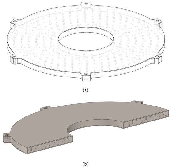
Figure 1.
The configuration involves a pressure vessel with two flat plates as the heating surface, enabling heat transfer fluid to flow through it and heat material on the top surface: (a) complete view; (b) section view.
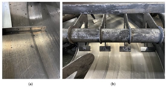
Figure 2.
The deformation pattern of the heating surface, (a) the size of permanent deformation, (b) the position of sliders and the grooves.
Initial analyses initially suggested that friction between sliders and plates could be a potential cause of the observed deformations. However, this hypothesis was refuted by the absence of corresponding deformations in sliders with similar material properties. Instead, hypotheses surrounding localized temperature increases at contact points, possibly influenced by variations in material temperatures introduced by processed substances, have emerged as more plausible explanations. The irregular and symmetrical nature of the observed deformations, which do not align with the expected patterns from material conveyance mechanisms, further complicates our understanding of these failure modes.
Given that material design considerations must adhere to the linear elastic regime of stainless steel, we can address the problem by employing the superposition principle, dividing it into two distinct issues: one focusing on pressure and the other on temperature. Regarding pressure, finite element method (FEM) modeling using a shell-type mesh has highlighted the critical role of pressure in design, providing assurance that the current design is safe for operation. However, a key question remains as follows: does temperature contribute significantly to the design force or is its impact negligible?
Fortunately, the analysis of a hollow circular plate under thermal loading represents one of the few mechanical engineering problems with a viable analytical model [11,12]. This analytical model significantly enhances our understanding of the plate’s response to high temperatures, enabling us to explore the influence of temperature conditions on stress distribution within the plate. Boley et al. have extensively studied the thermal deflections of axisymmetrically heated circular plates with fixed and simply supported edges [13]. They approached the problem by considering the plate exposed to a temperature gradient as a 2D body. The resulting displacement and stress equations for a disk free of traction on the boundaries, subject to plane stress conditions due to thermal stresses, are as follows:
The parameters corresponding to Equations (1) and (2) are detailed in Table 1. It is important to note that these equations apply specifically to the context of plane stress conditions within a thin plate, where the plate’s thickness is significantly smaller than its diameter—akin to the assumption underlying the shell-type mesh recommended by ASME for high-pressure vessels.

Table 1.
The geometrical parameters and material properties of the real case study.
Expanding on Equations (1) and (2), it may initially seem that a uniform temperature () would not induce any stress within the plate. However, is this truly accurate? Can we continuously raise a plate’s temperature without inducing stress? The response is affirmative under ideal conditions of uniform temperature application and the absence of external perturbations in order to keep the plate stress-free. Nevertheless, this ideal scenario is somewhat detached from reality, as the world rarely provides a disturbance-free environment. In essence, while the equilibrium equation may hold, the stability of this equilibrium under real-world conditions is a distinct matter—a concept known as the stability of equilibrium. In this context, it appears that temperature plays a critical role in inducing instability within high-pressure vessels, while pressure acts more like a disturbance force. This hypothesis forms the basis of the investigation that we aim to clarify in this article.
Another probable explanation for the observed deformations in the heating plates could be attributed to thermal buckling phenomena. Buckling phenomena, characterized by sudden structural instability under compressive stress, can occur across a diverse range of problems, including granular materials [14,15], fluid mechanics [16], and solid mechanics [17,18], profoundly impacting the behavior and integrity of systems in these fields. Thermal buckling, characterized by symmetrical deformation patterns, is a credible scenario for several reasons [19]. Studies have demonstrated that thermal buckling in circular plates can generate symmetric deformations under specific conditions [20,21]. Furthermore, thermal buckling can occur at stress levels lower than those typically captured by FEM simulations [22,23]. The disparity between FEM predictions and observed deformations underscores the credibility of this hypothesis. It is crucial to note that while FEM modeling predicts material behavior based on equilibrium equations, it may overlook the stability of these equations, particularly under thermal stress conditions. Therefore, an examination of the stability of equilibrium equations related to thermal stresses in circular plates could provide valuable insights into the root cause of these deformations.
This study seeks to deepen the understanding of mechanisms underlying thermal instabilities and deformations in high-temperature environments, providing insights into material behavior and critical design considerations essential for enhancing the reliability and performance of thermal processing systems.
This article presents the derivation of equilibrium equations governing thermal stress in circular annular plates (Section 2), followed by an evaluation of the stability of these equations (Section 3). Subsequently, it explores the factors that influence the thermal stability of these heating surfaces, along with an analysis of how design parameters impact thermal stability (Section 4). Finally, it provides a comprehensive discussion of critical design considerations (Section 5).
2. Mathematical Model of Circular Annular Plate
2.1. Kinetic and Kinematic Equations
Consider an annular plate of thickness h, inner radii b, and outer radii a, referred to as the polar coordinates (r, h, z), resting on an elastic foundation, as shown in Figure 3. In the present work, we assume that the modulus of elasticity E, thermal conductivity K, the thermal expansion coefficient , and Poisson’s ratio are considered to be constant across the thickness.
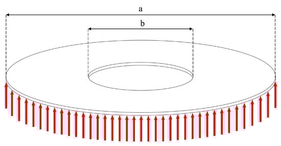
Figure 3.
Geometry and configuration of a thin circular annular plate on an elastic foundation.
The displacement field for the thin plate () may be written as [24]
where , , and represent the displacements on the middle surface () along the r, , and z directions, respectively. In this work, the assumption of classical plate theory (CPT) is adapted, and the effect of the transverse strains is ignored. Hence, based on the linear deformation assumptions in the polar coordinate system, the out-of-plan strains ( and ) can be written as follows [24]:
The last term of Equation (4) demonstrates that based on the assumption of CPT, the deflection does not vary through the thickness. In addition, the functions of and can be described as follows [24]:
Substituting Equation (5) into Equation (3) gives the displacement field equations for the thin circular plate as follows:
From Equation (6), the nonlinear strain-displacement relations will be written as follows [25]:
Based on Equation (7), the strain components consist of two terms. Therefore, the stain components can be written as
where , , , , , and are defined as follows [26]:
Within the framework of linear thermoelasticity, consistent with plane stress conditions, stress–strain relations are described as follows [27]:
where is the difference between the temperature distribution through the plate and the reference temperature.
Although the transverse strains (, , and ) are assumed to be identically zero based on the kinematics assumption of the classical plate theory, in reality, their energy conjugates (, , and ) are present to keep the plate in equilibrium. These stress components may be specified on the boundary. Thus, the transverse stresses must be accounted for in the boundary conditions and equilibrium of forces.
Stress resultants, based on the classical plate theory are related to the stress tensor components:
Substituting Equations (7) and (8) into Equation (9) give the stress resultants in terms of the mid-plane displacement as
where , , , , , and are defined by Equation (9). and are the thermal force and moment resultants are calculated as
If the temperature varies linearly within the thickness of the plate (, in which and are the temperature of the bottom and top of the plate, respectively), the thermal force and moment resultants can be calculated as
2.2. Equations of Motion
The equations of motion in classical plate theory are derived using the principle of virtual displacements. In these derivations, we incorporate thermal effects under the assumption that material properties remain independent of temperature, and the temperature T is known as a function of position (). Consequently, the temperature parameter only affects the formulation through constitutive equations (Equation (10)).
The dynamic version of the principle of virtual displacements or the minimum total potential energy, , is
where U is the strain energy, V is the work carried out by external forces, and K is the kinetic energy. Suppose that and are the distributed linear and rotational springs of the foundation. The virtual strain energy is given by
and the virtual work carried out by the external loads is given by
To derive the equilibrium equations of the classical plate, we substitute Equations (18) and (19) into Equation (17), utilize Equation (12), integrate the displacement gradients by parts to accommodate virtual displacements, and then perform mathematical simplifications. This process yields the following equilibrium equations for the classical plate [28]:
3. Stability Analysis of Circular Annular Plate
For all boundary conditions, in-plane compressive thermal loads are generated when immovability and periodicity conditions are met. The superscript 0 denotes the pre-buckling conditions. By neglecting the lateral deflection of the plate in the pre-buckling state and solving the symmetrical equilibrium equations, the results can be determined as
Therefore, by ignoring the nonlinear terms of Equation (12), the pre-buckling forces are obtained as follows:
while the extra pre-buckling moments exist which are equal to
According to Equation (23), in the pre-buckling state, no deflection occurs in the plate due to thermal loading, and the temperature gradient through the plate’s thickness is disregarded. Assuming an equilibrium state defined by displacement components , , and , the displacement components of a neighboring stable equilibrium state are , , and relative to the equilibrium position. Therefore, the total displacements of a neighboring state are [25,29]
Similar to displacements, the stress resultants are split into two components: one representing stable equilibrium and the other the neighboring state. The stress resultants with a superscript 1 are linear functions of the displacement with a superscript 1. Taking this into account, and utilizing Equations (12) and (20), the stability equations are simplified to become [30]
To derive the stability equations based on the displacement field, Equation (12) must be substituted into the preceding equations. After substitution, second and higher-order terms of incremental displacements can be omitted. The resulting equations are three stability equations derived from the classical plate theory for a circular annular plate in contact with two parameters of an elastic foundation, as
Equation (26) shows that the stability equations are decoupled by themselves if the material properties of the plate are assumed to be constant through the thickness direction. The last relation of Equation (26) can be written as
in which is defined as a flexural rigidity of the plate. Also, the above equation can be written as
For the sake of simplicity and generality, the following non-dimensional parameters are introduced:
By substituting Equation (29) into Equation (28), the stability equation of a circular annular plate in the form of non-dimensional can be written as
Hence, the thermal buckling condition can be driven by the equation below as follows:
In the pressure vessels system under analysis, the pins between the plates act as an elastic foundation to stabilize the heating surface. Therefore, the values of and for the pin system can be simplified as
in which is the cross-section area of each pin, is the polar moment of inertia of each pin, is the length of pins, is the number of pins, and and are the elastic and shear modulus of the pins, respectively.
3.1. Solving the Stability Equation
In order to solve Equation (31), it can be assumed that one suggested solution can be [31]
where n is the number of nodal diameters. The value of indicates the symmetric buckled shape of the plate, while is associated with the asymmetric buckled shape. By substituting Equation (33) into Equation (31), the following is obtained:
A non-trivial solution for Equation (34) is [31]
in which and are the Bessel functions of the first and second kind, respectively, and , , are constants that are evaluated by applying the associated boundary conditions. The top form of Equation (35) () is associated with symmetric buckling, while the bottom one () is related to asymmetric buckling.
As the heating surfaces are clamped at both inner and outer edges, they exhibit the bifurcation-type buckling for transverse thermal loading. Therefore, the boundary conditions are
By applying the boundary conditions from Equation (36) to Equation (35), a system of homogeneous equations is formed. For the symmetric buckling :
and for asymmetric buckling ():
To obtain a non-trivial solution for Equations (37) and (38), the determinant of the coefficient matrices must be set to zero, resulting in a nonlinear equation involving n and . To determine the non-dimensional critical buckling loads of the plate for every positive integer n, the corresponding determinant equations need to be solved [25]. This equation defines the stability criterion for the thermal buckling of circular annular plates. By identifying the smallest positive root of the equations for each n and selecting the smallest among them, the critical value of , denoted as , is obtained.
The amount of Equations (37) and (38) for are depicted in Figure 4, Figure 5, Figure 6 and Figure 7. The borders between the yellow and the blue in the figures indicate the zero amount of the determinant of Equations (37) and (38). Figure 4, Figure 5, Figure 6 and Figure 7 show that the minimum amount of , which is called , occurred when .
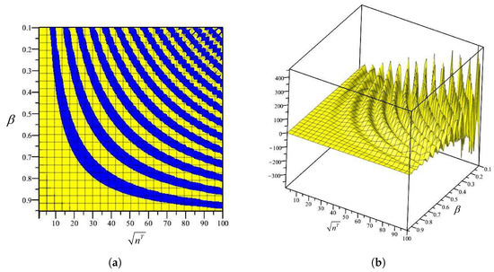
Figure 4.
The amount of determinant of Equation (37) for (the blue indicates a positive and the yellow shows a negative amount). (a) two-dimensional view of the solution, (b) three-dimensional view of the solution.
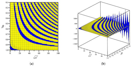
Figure 5.
The amount of determinant of Equation (38) for (the blue indicates a positive and the yellow shows a negative amount). (a) two-dimensional view of the solution, (b) three-dimensional view of the solution.
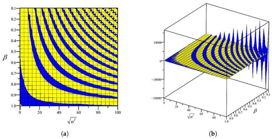
Figure 6.
The amount of determinant of Equation (38) for (the blue indicates a positive and the yellow shows a negative amount). (a) two-dimensional view of the solution, (b) three-dimensional view of the solution.

Figure 7.
The amount of determinant of Equation (38) for (the blue indicates a positive and the yellow shows a negative amount). (a) two-dimensional view of the solution, (b) three-dimensional view of the solution.
3.2. Case Study: A Real Heating Surface with Molten Salt
To explore the initial hypothesis regarding plastic deformation of a heating plate, a practical case study was conducted under controlled conditions using molten salt as a heat transfer fluid to ensure uniform radial temperature distribution [32]. The selection of 304 stainless steel (SS304) for the heating plate reflects a careful balance between corrosion resistance and cost-effectiveness in industrial applications [33,34]. This study exemplifies thermal stability analysis in a real-world heat transfer system, focusing on the behavior of a specific heating plate under operational conditions. By investigating thermal buckling phenomena, the analysis demonstrates that the heating plate operates within an unstable zone, where any perturbations could disrupt its equilibrium and potentially lead to plastic deformation or failure.
In this study, the heating plate is assumed to be clamped at both its inner and outer edges due to welding at these boundaries. The inner diameter ( inches) and outer diameter ( inches) of the plate configuration are chosen to represent typical dimensions encountered in industrial heating surface designs. The thermal properties of SS304, including its elastic modulus ( GPa), Poisson’s ratio (), and thermal expansion coefficient ( ), provide critical insights into material behavior under high-temperature conditions [35]. This case study serves as a practical demonstration of thermal instability in heating surface configurations, underscoring the importance of robust design considerations for ensuring structural integrity and performance in heat transfer systems.
To perform thermal stability analysis, we substitute into Equations (37) and (38) and utilize MAPLE 2022.0 software to solve these equations, yielding the non-dimensional critical buckling parameter . This parameter is then used to calculate the critical temperature of buckling for the circular annular plate using the formula:
The results of these calculations are summarized in Table 2.
Table 2.
Critical buckling temperature difference of the heating surfaces (thickness = in).
4. Design Parameters Analysis
Designing plates for high-temperature applications presents significant challenges in selecting appropriate dimensions and materials. In this section, key design parameters essential for the design of pressure vessels operating at elevated temperatures are explored. Specifically, the scalability of the vessel, the utilization of alternative stainless steel compositions, and the impact of increased plate thickness are investigated. Each of these design parameters influences the critical thermal buckling temperature, providing valuable insights into optimizing plate design for high-temperature environments.
4.1. Scalability Assessment
The scalability of a heating system in certain applications could offer economic benefits. For instance, employing larger heating plates could enhance the overall heating process efficiency. Therefore, assessing the performance of larger heating plates under similar clamping conditions at both inner and outer edges, constrained by welding considerations, is advantageous. The material of choice is assumed to be SS304, with specified inner and outer diameters of inches and inches, respectively.
To assess the critical temperature for thermal buckling of these larger plates, the non-dimensional critical buckling parameter is calculated using the value , substituted into Equations (37) and (38). The resulting values are computed using MAPLE software to determine the critical buckling temperature difference based on Equation (39). The summarized outcomes of these calculations are presented in Table 3 and Table 4 for plate thicknesses of 0.375 and 0.5 inches, providing insights into the critical buckling behavior under varying thicknesses for the planned larger heating plates. These findings contribute to the ongoing design considerations aimed at optimizing the thermal stability and performance of the heating surfaces.
Table 3.
Critical buckling temperature difference of the larger heating plates (thickness = in).
Table 4.
Critical buckling temperature difference of the larger heating plates (thickness = in).
By comparing the critical thermal buckling temperatures of the initial case study problem where the inner and outer diameters were 34 and 96 inches (as summarized in Table 3) with the current scaled-up heating plate featuring inner and outer diameters of 42 and 144 inches (as summarized in Table 3), it can be concluded that increasing the outer diameter may decrease the critical temperature for thermal buckling of the plate. This finding is valuable for engineers seeking to balance economic efficiency with ensuring the stability of heating surfaces.
4.2. Effect of Thermal Expansion Coefficient ()
Given the presence of molten salts and the associated high risk of corrosion, the selection of materials for heating surfaces is considerably restricted. Consequently, our options for heating plates are primarily limited to austenitic stainless steel due to its robust performance under such demanding conditions. Austenitic stainless steels are renowned for their ability to withstand high temperatures while retaining excellent corrosion resistance.
To facilitate informed material selection for future heating plate designs, Table 5 summarizes some of the most commonly used austenitic stainless steels along with their respective critical buckling temperatures. This information serves as a valuable reference for identifying suitable materials that can effectively withstand the thermal and corrosive challenges posed by molten salt environments, supporting the development of durable and reliable heating surfaces for industrial applications.
Table 5.
Comparison of the critical temperature for a symmetric buckling of different stainless steels for the larger heating surface (thickness = in).
As is shown in Table 5, using SS310 instead of SS304 will increase the critical temperature of buckling by 20%. Therefore, it can be suggested as a solution for enhancing the critical temperature difference for the buckling of heating plates.
4.3. Effect of Thickness of Plate (h)
The thickness of the plate not only impacts the cost and weight of the system but also plays a critical role in influencing the thermal buckling behavior of heating surfaces. In this section, we explore the effect of thickness on thermal buckling. As shown in Figure 8, increasing the plate thickness enhances its resistance to buckling, as evidenced by the relationship between thickness and critical buckling temperature difference illustrated in the figure.

Figure 8.
Effect of the thickness of plate on the critical thermal buckling temperature for the larger heating surface (, in).
Based on Figure 8, it is evident that thicker plates exhibit higher critical buckling temperatures, indicating improved buckling resistance with increased thickness. However, the relationship between thickness and critical thermal buckling temperature is nonlinear. For instance, increasing the thickness from 1 to 2 inches raises the critical thermal buckling temperature by 78 °C, whereas increasing the thickness from 4 to 5 inches results in a 256 °C increase in critical temperature. Therefore, one effective approach to mitigate thermal buckling in heating surfaces could be to increase plate thickness. This strategy enhances the structural integrity of heating surfaces, reducing the risk of buckling under high-temperature conditions. Engineers can leverage this insight when designing high-temperature flanges to prevent mechanical instability.
4.4. Effect of the Inner and Outer Diameter Ratio ()
Another variable that significantly influences the critical thermal buckling temperature is the ratio of the inner diameter to the outer diameter of the plate. This ratio, depicted in Figure 9, demonstrates the relationship between the critical temperature and the diameter proportions for plates with thicknesses of 0.375 and 0.5 inches.
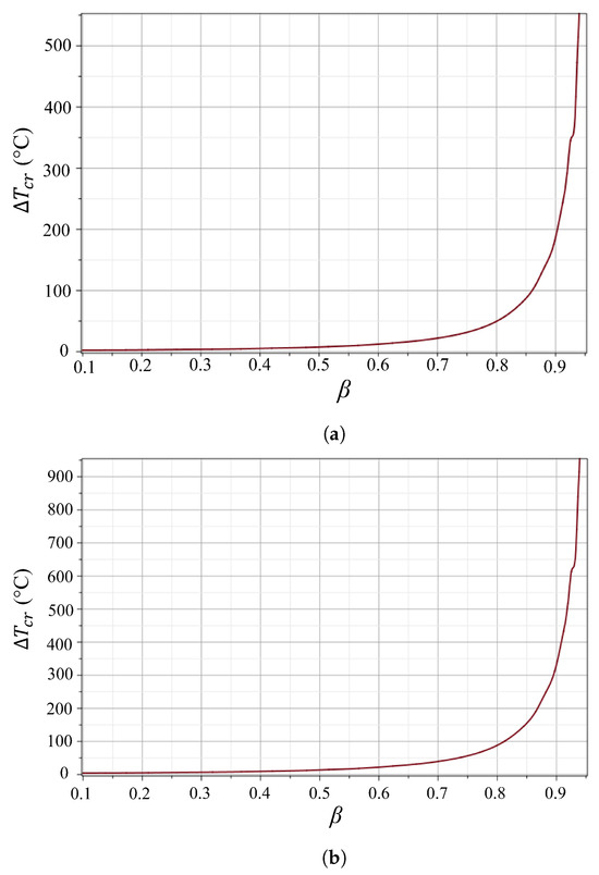
Figure 9.
The effect of the inner and outer diameter ratio () on the critical temperature of thermal buckling: (a) the thickness of plate = 0.375 in; (b) the thickness of plate = 0.5 in.
In Figure 9, we observe that the effect of the diameter ratio on the critical temperature is most pronounced when the ratio exceeds 0.8. Below this threshold, the influence of the diameter ratio on the critical temperature appears to be minimal or negligible. This observation underscores the importance of considering the diameter ratio when designing heating surfaces to mitigate thermal buckling, particularly for ratios exceeding 0.8, where changes in the diameter proportions can notably impact the critical buckling temperature. Understanding this relationship is crucial for optimizing the design parameters of heating surfaces to ensure stability and performance under high-temperature conditions. This insight can also be valuable for engineering applications, particularly in designing flanges for high temperatures to mitigate the risk of permanent deformation and prevent seal failure under elevated temperature conditions.
5. Conclusions
The aim of this article is to demonstrate how elevated temperatures in pressure vessels composed of flat plates can induce an unstable condition, where any perturbation could lead to structural failure. This study highlights that, even when adhering to ASME guidelines for employing shell-type mesh in FEM simulations of pressure vessels, the critical influence of temperature on destabilizing equilibrium is not adequately captured by the ASME-recommended FEM modeling.
In conclusion, this work has investigated the potential for thermal buckling in pressure vessels at elevated temperatures, yielding several key findings:
- Edge Boundary Conditions: Clamped edges increase the critical buckling temperature, enhancing stability.
- Plate Thickness: Thicker plates show greater resistance to thermal buckling.
- Diameter Ratio: Increasing the inner diameter, while keeping the outer diameter constant, raises the critical buckling temperature.
- Material Selection: Materials with lower thermal expansion coefficients improve thermal buckling resistance.
- Elastic Foundation: Clamping the plates together, effectively creating an elastic foundation through additional pinning and fixing between the plates, increases the critical buckling temperature.
These findings offer crucial insights for optimizing the design and material selection of heating surfaces, thereby reducing the risk of thermal buckling and enhancing the reliability and performance of high-temperature processing systems. By focusing on these key design parameters, engineers can develop more robust heating surfaces capable of withstanding extreme thermal conditions.
Further research and experimentation in these areas can lead to more effective strategies for designing robust heating surfaces capable of withstanding extreme thermal conditions. Engineers and designers should prioritize understanding thermal buckling phenomena when designing high-temperature pressure vessels. Based on the findings of this study, it is recommended to explore alternative mesh types, such as 3D solid mesh, for FEM modeling of pressure vessels composed of flat plates operating at high temperatures. This approach will help ensure accurate safety predictions and enhance the reliability of pressure vessel designs under extreme thermal conditions.
Author Contributions
Conceptualization, methodology, validation, formal analysis, investigation, data curation, and writing—original draft preparation, A.S.-C.; writing—review and editing, F.A.-M.; supervision, A.S.-C.; project administration, A.S.-C. All authors have read and agreed to the published version of the manuscript.
Funding
This research received no external funding.
Data Availability Statement
Data are contained within the article.
Conflicts of Interest
The authors declare no conflicts of interest.
References
- Singh, K.P.; Soler, A.I. Mechanical Design of Heat Exchangers: And Pressure Vessel Components; Springer Science & Business Media: Berlin/Heidelberg, Germany, 2013. [Google Scholar] [CrossRef]
- Moyya, S.; Thejasree, P.; Abraham, B.C.; Mangalathu, G.S. Design and analysis of single and multi-layer pressure vessel. Mater. Today Proc. 2023; in press. [Google Scholar] [CrossRef]
- Vignarooban, K.; Xu, X.; Wang, K.; Molina, E.; Li, P.; Gervasio, D.; Kannan, A.M. Vapor pressure and corrosivity of ternary metal-chloride molten-salt based heat transfer fluids for use in concentrating solar power systems. Appl. Energ. 2015, 159, 206–213. [Google Scholar] [CrossRef]
- Mahmoudinezhad, S.; Sadi, M.; Ghiasirad, H.; Arabkoohsar, A. A comprehensive review on the current technologies and recent developments in high-temperature heat exchangers. Renew. Sustain. Energy Rev. 2023, 183, 113467. [Google Scholar] [CrossRef]
- Mohiddin, M.N.B.; Tan, Y.H.; Seow, Y.X.; Kansedo, J.; Mubarak, N.; Abdullah, M.O.; San Chan, Y.; Khalid, M. Evaluation on feedstock, technologies, catalyst and reactor for sustainable biodiesel production: A review. J. Ind. Eng. Chem. 2021, 98, 60–81. [Google Scholar] [CrossRef]
- Thakur, A.; Kumar, R.; Kumar, S.; Kumar, P. Review of developments on flat plate solar collectors for heat transfer enhancements using phase change materials and reflectors. Mater. Today Proc. 2021, 45, 5449–5455. [Google Scholar] [CrossRef]
- Kruizenga, A.; Gill, D. Corrosion of iron stainless steels in molten nitrate salt. Energ. Proc. 2014, 49, 878–887. [Google Scholar] [CrossRef]
- Ali, M.; Ul-Hamid, A.; Alhems, L.M.; Saeed, A. Review of common failures in heat exchangers—Part I: Mechanical and elevated temperature failures. Eng. Fail. Anal. 2020, 109, 104396. [Google Scholar] [CrossRef]
- Toudehdehghan, A.; Hong, T.W. A critical review and analysis of pressure vessel structures. In Proceedings of the 1st International Postgraduate Conference on Mechanical Engineering (IPCME2018), Pekan, Malaysia, 31 October 2018; IOP Conference Series: Materials Science and Engineering. IOP Publishing: Bristol, UK, 2019; Volume 469, p. 012009. [Google Scholar] [CrossRef]
- ASME BPVC Section VIII-Rules for Construction of Pressure Vessels-Div. II—Alternative Rules; The American Society of Mechanical Engineers. 2023. Available online: https://www.asme.org/codes-standards/find-codes-standards/bpvc-viii-2-bpvc-section-viii-rules-construction-pressure-vessels-division-2-alternative-rules/2023/print-book (accessed on 1 July 2024).
- Khodamorad, S.; Alinezhad, N.; Fatmehsari, D.H.; Ghahtan, K. Stress corrosion cracking in Type. 316 plates of a heat exchanger. Case Stud. Eng. Fail. Anal. 2016, 5, 59–66. [Google Scholar] [CrossRef]
- Jabbari, M.; Nejad, M.Z. Mechanical and thermal stresses in radially functionally graded hollow cylinders with variable thickness due to symmetric loads. Aust. J. Mech. Eng. 2020, 18, S108–S121. [Google Scholar] [CrossRef]
- Boley, B.A.; Weiner, J.H. Theory of Thermal Stresses; Wiley: Hoboken, NJ, USA, 1960. [Google Scholar] [CrossRef]
- Sadeghi-Chahardeh, A.; Mollaabbasi, R.; Picard, D.; Taghavi, S.M.; Alamdari, H. Discrete element method modeling for the failure analysis of dry mono-size coke aggregates. Materials 2021, 14, 2174. [Google Scholar] [CrossRef]
- Sadeghi-Chahardeh, A.; Mollaabbasi, R.; Picard, D.; Taghavi, S.M.; Alamdari, H. Effect of particle size distributions and shapes on the failure behavior of dry coke aggregates. Materials 2021, 14, 5558. [Google Scholar] [CrossRef]
- Sarbanha, A.A.; Larachi, F.; Taghavi, S.M. Bubble and particle dynamics in a thin rectangular bubbling fluidized bed under emulated marine instabilities. Chem. Eng. Sci. 2023, 280, 119041. [Google Scholar] [CrossRef]
- Li, X.; Shlosman, I.; Pfenniger, D.; Heller, C. The origin of buckling instability in galactic bars: Searching for the scapegoat. Mon. Not. R. Astron. Soc. 2023, 520, 1243–1257. [Google Scholar] [CrossRef]
- Yang, Z.; Liu, A.; Lai, S.K.; Safaei, B.; Lv, J.; Huang, Y.; Fu, J. Thermally induced instability on asymmetric buckling analysis of pinned-fixed FG-GPLRC arches. Eng. Struct. 2022, 250, 113243. [Google Scholar] [CrossRef]
- Hajlaoui, A.; Chebbi, E.; Dammak, F. Three-dimensional thermal buckling analysis of functionally graded material structures using a modified FSDT-based solid-shell element. Int. J. Press. Vessel. Pip. 2021, 194, 104547. [Google Scholar] [CrossRef]
- Wang, C.M.; Wang, C.Y. Exact Solutions for Buckling of Structural Members; CRC Press: Boca Raton, FL, USA, 2004. [Google Scholar] [CrossRef]
- Zhang, J.; Zhao, Q.; Wang, X.; Ullah, S.; Zhao, D.; Civalek, Ö.; Xue, C.; Qi, W. New exact analytical thermal buckling solutions of composite thin plates with all edges rotationally-restrained. Mech. Adv. Mater. Struct. 2024, 31, 3518–3530. [Google Scholar] [CrossRef]
- Ghiasian, S.; Kiani, Y.; Sadighi, M.; Eslami, M. Thermal buckling of shear deformable temperature dependent circular/annular FGM plates. Int. J. Mech. Sci. 2014, 81, 137–148. [Google Scholar] [CrossRef]
- Weisz-Patrault, D.; Margerit, P.; Constantinescu, A. Residual stresses in thin walled-structures manufactured by directed energy deposition: In-situ measurements, fast thermo-mechanical simulation and buckling. Addit. Manuf. 2022, 56, 102903. [Google Scholar] [CrossRef]
- Reddy, J.N. Theory and Analysis of Elastic Plates and Shells; CRC Press: Boca Raton, FL, USA, 2006. [Google Scholar] [CrossRef]
- Kiani, Y.; Eslami, M. An exact solution for thermal buckling of annular FGM plates on an elastic medium. Compos. B Eng. 2013, 45, 101–110. [Google Scholar] [CrossRef]
- Eslami, M.R. Buckling and Post-buckling of Beams. In Buckling and Postbuckling of Beams, Plates, and Shells; Springer International Publishing: Cham, Switzerland, 2018; pp. 7–110. [Google Scholar] [CrossRef]
- Eslami, M.R. Thermal Stresses in Plates. In Thermal Stresses in Plates and Shells; Springer: Berlin/Heidelberg, Germany, 2024; pp. 43–143. [Google Scholar] [CrossRef]
- Javani, M.; Kiani, Y.; Eslami, M.R. Nonlinear dynamic response of a temperature-dependent FGM spherical shell under various boundary conditions and thermal shocks: Examination of dynamic snap-through. Thin-Walled Struct. 2024, 199, 111796. [Google Scholar] [CrossRef]
- Babaei, H.; Kiani, Y.; Reza Eslami, M. Perturbation method for thermal post-buckling analysis of shear deformable FG-CNTRC beams with different boundary conditions. Int. J. Struct. Stab. Dyn. 2021, 21, 2150175. [Google Scholar] [CrossRef]
- Qolipour, A.M.; Eipakchi, H.; Nasrekani, F.M. Asymmetric/Axisymmetric buckling of circular/annular plates under radial load using first-order shear deformation theory. Thin-Walled Struct. 2023, 182, 110244. [Google Scholar] [CrossRef]
- Bagheri, H.; Kiani, Y.; Eslami, M. Asymmetric thermal buckling of annular plates on a partial elastic foundation. J. Therm. Stress. 2017, 40, 1015–1029. [Google Scholar] [CrossRef]
- Kuchibhotla, A.; Banerjee, D.; Dhir, V. Forced convection heat transfer of molten Salts: A review. Nucl. Eng. Des. 2020, 362, 110591. [Google Scholar] [CrossRef]
- Fernández, A.; Galleguillos, H.; Fuentealba, E.; Pérez, F. Corrosion of stainless steels and low-Cr steel in molten Ca(NO3)2-NaNO3-KNO3 eutectic salt for direct energy storage in CSP plants. Sol. Energy Mater. Sol. Cells 2015, 141, 7–13. [Google Scholar] [CrossRef]
- Walczak, M.; Pineda, F.; Fernandez, A.G.; Mata-Torres, C.; Escobar, R.A. Materials corrosion for thermal energy storage systems in concentrated solar power plants. Renew. Sustain. Energy Rev. 2018, 86, 22–44. [Google Scholar] [CrossRef]
- Sheets, A.S.G.D. Atlas steels technical handbook of stainless steels. Stainl. Steel 2013, 630, 17–4PH. [Google Scholar] [CrossRef]
- Cverna, F. (Ed.) ASM Ready Reference: Thermal Properties of Metals; ASM International: Almere, The Netherlands, 2002. [Google Scholar]
Disclaimer/Publisher’s Note: The statements, opinions and data contained in all publications are solely those of the individual author(s) and contributor(s) and not of MDPI and/or the editor(s). MDPI and/or the editor(s) disclaim responsibility for any injury to people or property resulting from any ideas, methods, instructions or products referred to in the content. |
© 2024 by the authors. Licensee MDPI, Basel, Switzerland. This article is an open access article distributed under the terms and conditions of the Creative Commons Attribution (CC BY) license (https://creativecommons.org/licenses/by/4.0/).