Abstract
Quadrupedal robots are now not just prototypes as they were a decade ago. This field now focuses on finding new application areas for robots rather than solving pure locomotion problems. Although the price of quadrupedal robots has decreased significantly during the last decade, it is still relatively high and can be considered as one of the limiting factors for research, especially for multi-agent scenarios involving multiple robots. This paper proposes a simple and easily reproducible approach to integrating the cheapest robot from the Unitree Go1 series with controllers running the ArduPilot firmware without disassembling the robot itself or modifying its hardware. Experimental studies show that the average latency introduced by the proposed control method over Wi-Fi is 206.7 ms, and its standard deviation is below 53 ms, which is suitable for following the mission route using the Global Navigation Satellite System (GNSS). At the same time, control using Ethernet reduces mean latency down to 78.3 ms and provides additional functionality (e.g., the ability to configure step height). Finally, in the range of standard Go1 speeds, both proposed control interfaces, based on Wi-Fi and Ethernet, are suitable for most practical indoor and outdoor tasks.
1. Introduction
Quadrupedal robots have made a giant leap from simple prototypes to market-ready products over the past few decades [1,2,3]. Currently, the focus in this field has started to shift from pure locomotion problems to finding new application areas for these robots [2,4]. In such projects, researchers and engineers often do not use low-level access to motion control. Instead, they need to move the robot in the environment, utilizing the advantages of quadrupedal locomotion. There are also many applications, such as street cleaning [5], where walking locomotion can provide additional benefits, but engineers are motivated to implement an off-the-shelf solution instead of designing a quadruped robot from scratch.
The price of quadrupedal robots has decreased significantly during the last decade. For example, in 2015, the cost below USD 10,000 was considered low for such a class of robots, and by the beginning of 2021, there were already several open-source quadrupedal robots with costs starting from USD 3000. Moreover, in 2021, the Chinese company Unitree introduced the Go1 series (Table 1 (https://shop.unitree.com/products/unitreeyushutechnologydog-artificial-intelligence-companion-bionic-companion-intelligent-robot-go1-quadruped-robot-dog, (accessed on 1 April 2025))), the price of which started from USD 2700, making it the most affordable robot on the market at the end of 2021 [6]. Up to the date of current research, according to Google Scholar, several dozen papers have published experiments performed using Go1 robots. At the same time, nearly all researchers chose to use the most expensive robot from the series: Go1 Edu. Although it is equipped with additional sensors and provides more computational resources, the main reason for using this robot for many researchers is that it is the only one Unitree provides a programming interface for (Table 1). The Go1 Air modification is presented as a high-technology toy designed for fun but not for research. The actual price of the Go1 Edu is not public and may differ between customers, but according to our knowledge and the data provided by [7], it is more than three times the price of the Air version. The price of a single robot around USD 10,000 is mainly a problem for students and independent researchers. However, when it comes to multi-agent scenarios requiring many robots, it becomes a limiting factor, even for laboratories and universities, especially in developing countries.

Table 1.
Unitree Go1 series robots comparison.
The Go1 software and hardware analysis performed by the users’ community showed that all three versions (Air, Pro, and Edu) are very similar [7]. Moreover, some Edu features are locked (or not provided) on the software level. They can be activated/added by changes in the onboard computer’s operating system configuration and using the community open source software development kit [8]. Thus, gaining control over any Go1 robot is possible by executing custom software on its onboard computer. At the same time, the legality of running such solutions on Air and Pro versions still needs to be investigated as it requires logging into the onboard computer using credentials not provided to the customer by a vendor. Also, it can be a reason for the vendor to cancel the warranty.
In recent years, there have been several attempts to create a low-cost quadruped robot for education and research. The Pusan National University team introduced the PADWQ robot [9], which is built entirely from off-the-shelf components and standard 3D-printed plastic structural parts. This robot is capable of highly dynamic locomotion and is reliable and robust for long, continuous operation. At the same time, its price is over USD 7000. MIT Super Mini Cheetah [10] is another quadruped robot that the authors claim to have a cost of less than USD 10,000. Its well-known successor, MIT Mini Cheetah [11], costs over USD 3600. These robots are comparable to Unitree in terms of dynamics and have a lower cost than the Go1 Edu version, making them promising for research focused on locomotion. At the same time, their price is still significantly higher than that of Go1 Air. Moreover, building one of them from scratch requires a lot of effort.
There are cheaper quadruped robot projects (e.g., Pupper, Solo, D’Kitty) [12]. Their hardware and “out-of-the-box” locomotion capabilities are less than those of Unitree Go1 Air. At the same time, their price is comparable or higher, making them a less attractive choice for research focused on applications of quadruped robots.
As an alternative, we propose a simple solution to control the robot via the internal Ethernet interface or its wireless MQTT interface provided by the vendor and supported by all Go1 modifications. This approach works on any Go1 robot «out-of-the-box» without any changes in its hardware or software.
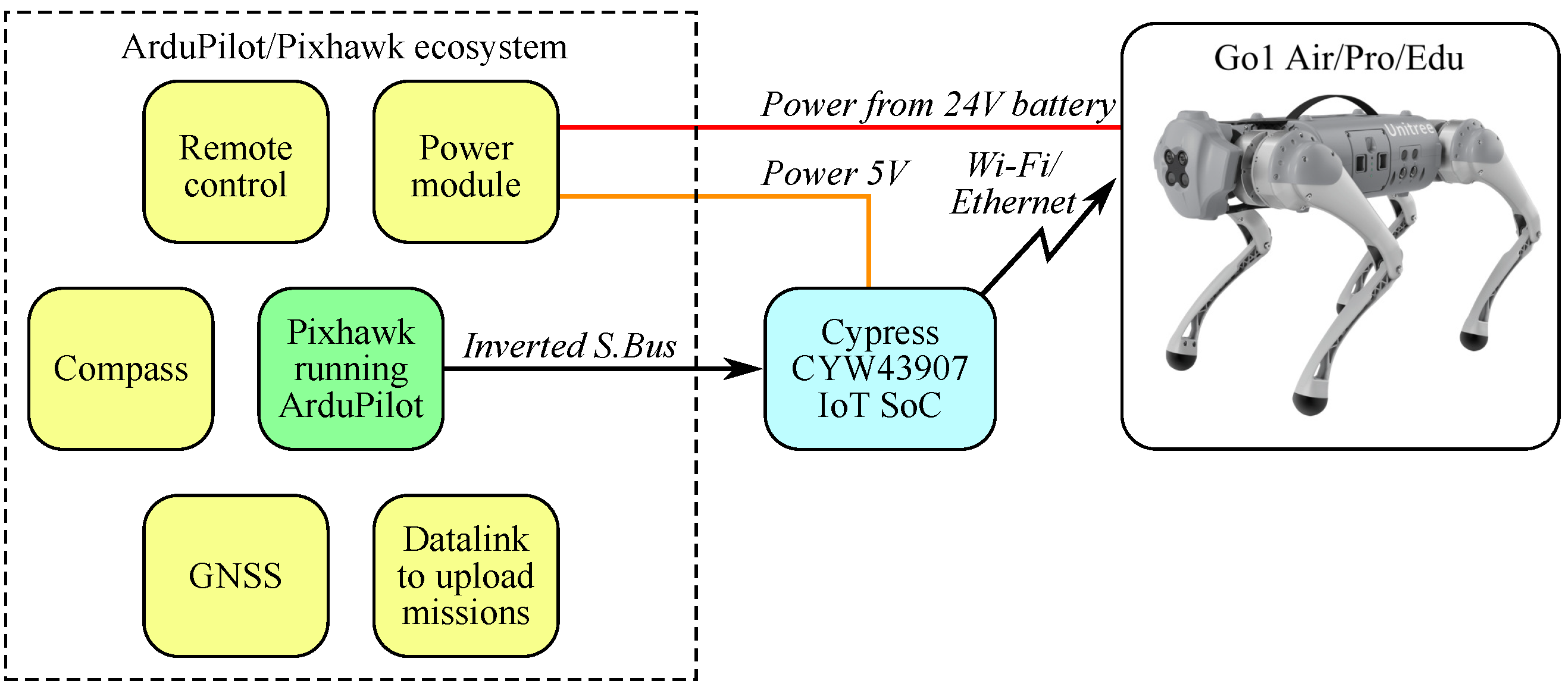
The control signals in our design are provided by the Pixhawk rover controller running ArduPilot firmware using S.Bus protocol (Figure 1). The ArduPilot ecosystem is well known by many researchers [13,14,15,16] and supports many peripheral devices, making it possible to customize robots for different applications, both indoor and outdoor. For example, ref. [17] in-detail describes an easy-to-customize, low-cost solution for remote imagery designed for vehicles controlled by ArduPilot. Finally, using an ArduPilot-based controller simultaneously provides navigation, including Inertial Measurement Unit (IMU) and Global Navigation Satellite System (GNSS) sensor fusions, remote control commands processing, following predefined missions, detecting failsafe conditions, and solving many other tasks of autonomous mobile robot control. Additionally, the application-specific functionality can be integrated into ArduPilot by using Lua scripts without recompiling the core source code of the firmware. However, it should be mentioned that the computing resources of the ArduPilot-based controller are limited. Therefore, if the application requires complex calculations, using a dedicated embedded computer connected to ArduPilot through MAVLink is better.
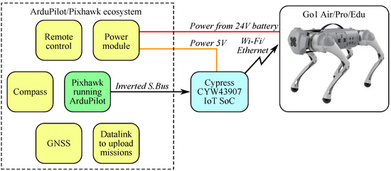
Figure 1.
Structure of the proposed Go1 control system.
The key contributions of this paper are as follows: (1) a schematic and corresponding open-source IoT SoC firmware to control the Go1 quadruped robot with ArduPilot using only five wires and a single low-cost development kit; (2) an experimental analysis and comparison of latencies introduced by Wi-Fi/MQTT and Ethernet/UDP interfaces between ArduPilot and Go1; (3) experimental results demonstrating that both proposed interfaces are suitable for indoor and outdoor mission-based control of the Go1 robot.
2. Materials and Methods
The aim of this paper is to demonstrate that the Go1 Air quadruped robot, positioned as a toy by its manufacturer (Unitree Robotics, Hangzhou City, China), can be transformed with minimal modifications into an autonomous robot capable of executing a pre-programmed mission. Our approach is initially focused on using Go1 Air’s “out-of-the-box” capabilities instead of practicing with new types of locomotion. We chose Pixhawk with ArduRover firmware as the navigation controller for the following reasons: It is low cost and open source, can be customized by Lua scripts without recompiling, solves both navigation and mission control tasks, and supports a wide range of accessory hardware. Typically, ArduPilot’s legged robot control is based on defining the entire locomotion pattern through the Lua scripts. At the same time, the internal motion controller of the Go1 Air robot already perfectly solves the task of moving the robot and adjusting its orientation, but it lacks navigation and autonomous capabilities. Instead of developing a new locomotion controller for ArduPilot or a new navigation controller for Go1 Air from scratch, we introduced a converter module that allows Go1 Air to be controlled directly by a navigation controller with ArduRover firmware. Our approach uses widely available hardware and can be easily replicated with minimal effort.
Initially, Go1 robots in Air or Pro versions could not be integrated with third-party sensors. Even the most expensive version, Expensive Edu, can only connect to sensors with a USB or Ethernet interface. In addition, configuring and integrating these sensors requires significant effort in terms of driver support and programming. At the same time, the PixHawk platform supports a wide range of low-cost navigation and obstacle avoidance sensors that are out-of-the-box. Most of them can be configured directly from the MissionPlanner software (v.1.3.80 or higher, the rest require the execution of Lua scripts provided by the manufacturers or the ArduPilot community. In addition, if the engineer prefers to use ROS/ROS2 for a custom solution, there is a ready-to-use MAVROS package v.2.9.0 or higher to control the whole robot through the MAVLink interface. The MAVLink interface can also be used to integrate the Go1 robot with application-specific solutions designed for supervised control of ArduPilot/PX4 rovers. Thus, the proposed approach reduces the cost and effort of integrating additional sensors and/or external software.
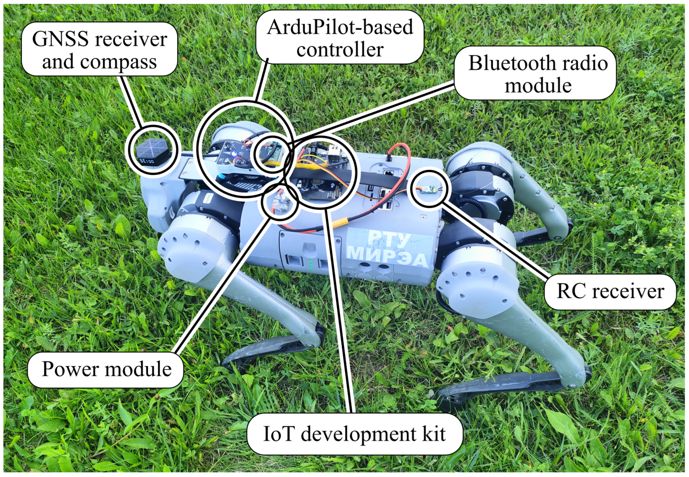
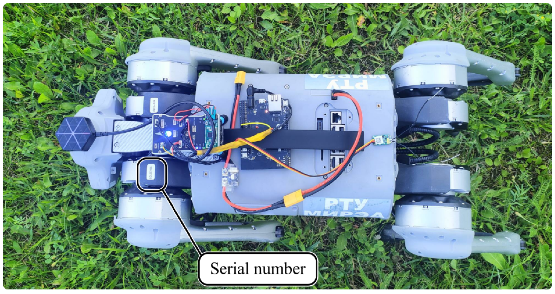
The structure of the proposed Go1 control system is introduced in Figure 1. The ArduPilot ecosystem of the prototype (Figure 2) used for experimental studies included the Pixhawk 2.4.8 controller, Radiolink SE100 GNSS/compass module, FrSky XM+ remote control (RC) receiver, and HC-42 Bluetooth Serial Port, which was used as datalink to upload missions. These components are inexpensive and available worldwide. There are many ArduPilot-compatible controllers on the market, both proprietary and open-source (https://ardupilot.org/rover/docs/common-autopilots.html, (accessed on 1 April 2025)), creating an opportunity to precisely tune the tradeoff between cost and performance of the control system. The setup described in this paper can be considered one of the cheapest and still suitable for outdoor control of the Go1 Quadrupedal Robot. Meanwhile, its IMU, compass, and GNSS receiver cannot provide sub-meter precision during autonomous missions. For such cases, we recommend using the CUAV X7 controller and CUAV C-RTK 9P GNSS, with which we had a positive experience in a previous industrial-grade project. At the same time, using more advanced controllers and peripheral components will raise the cost of the overall setup, but even so, in most cases, it will be cheaper than Go1 Edu. If the quadrupedal robot should operate indoors, ArduPilot-based system navigation can be implemented using MarvelMind ultra-sonic beacons (https://marvelmind.com/, (accessed on 1 April 2025)). They can successfully replace both GNSS and a compass (replacing the compass will require using two beacons: one near the head and the other mounted in the rear part of the robot on a distance ≥0.4 m from the first one). We previously used those ultra-sonic beacons to navigate the ArduPilot-based multicopter in one of our previous studies [18] and tested it with the Go1 Air setup described in the current paper. In both cases, the precision and update rate of the MarvelMind indoor navigation was satisfactory for autonomous mission following (indoor version of Go1 Air control system setup is not described in this paper, because MarvelMind navigation system configuration highly depends on the specific room conditions and will shift too much attention from the general control concept). In the current paper, the GNSS sensor is used as the main example because it is much easier to configure than other navigation approaches. A detailed description of other alternatives can be found in the ArduPilot documentation.
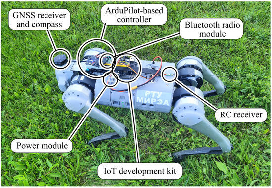
Figure 2.
Go1 Air robot equipped with the proposed control system.
In this project, ArduPilot Rover firmware v.4.2.3 was used (the support of all the used features in previous and newer versions should be further investigated). The controller was configured to output all control signals through the S.Bus interface using one of its Universal Asynchronous Receiver/Transmitter (UART) ports. S.Bus is a well-known protocol in remote control vehicles and drone design. Futaba introduced it as a proprietary digital protocol that connects remote controller receivers and RC-model servo actuators. By the current date, it was successfully reversed engineered (Concise S.Bus protocol description can be found at https://github.com/uzh-rpg/rpg_quadrotor_control/wiki/SBUS-Protocol, (accessed on 1 April 2025)) and supported by many other vendors. S.Bus protocol cyclically transmits immediate values of 16 11-bit control channels, two dual-state channels, and two failsafe flags. Native S.Bus devices use inverted 100 kbps UART on the physical layer. ArduPilot-compatible controllers usually have one S.Bus output, but to receive its data, the external microcontroller should have an onboard inverter connected to its UART port. Another alternative is configuring ArduPilot firmware to use one of the controller’s UART ports to transmit S.Bus frames. In this case, data are transmitted non-inverted (assuming that inverter is installed externally (https://ardupilot.org/rover/docs/common-sbus-out.html, (accessed on 1 April 2025)) and can be processed by most of the devices on the market. The default S.Bus frame rate is 50 Hz. Dedicated SBUS output can be tuned in a range from 25 to 250 Hz, but in the firmware version used in the current project, this tuning does not affect SBUS output over UART. At the same time, 50 Hz is a good compromise for the proposed approach: A lower rate may degrade control performance, and at a higher rate, it would be challenging to send MQTT messages over Wi-Fi using low-cost wireless SoCs. At the same time, the experimental results presented in Section 4 show that the latency of communication protocols implemented using the proposed approach exceeds 50 ms. Therefore, there is no practical reason to reduce the control cycle below 20 ms.
All Unitree Go1 robots are equipped with a Wi-Fi access point, which is used for communication with the Unitree mobile application. The list of MQTT topics published by this application was revealed by [7] and presented in Table 2. Symbols , , , in the last row of Table 2 define position of the left (, ) and right (, ) control sticks. Additionally, Table 2 contains information about the Quality of Server (QoS) level chosen for each topic in the current project.

Table 2.
MQTT topics used to control Go1.
ArduRover-based controllers do not natively support MQTT and generally do not have an in-built Wi-Fi transceiver. Thus, an external device is needed to decode S.Bus messages from the ArduRover firmware and retransmit them to Go1 as MQTT messages. In the initial stage of this project, we tried to use the ESP32 module for this purpose, but it was not able to provide robust transmission of MQTT messages at a 50 Hz rate synchronously to S.Bus decoding. To overcome this problem, we switched to Cypress IoT SoC CYW43907 (Infineon Technologies, Neubiberg, Germany). Additional motivation to use this SoC was that the firmware of its wireless transceiver is compatible with the Nexmon framework [19] and can be patched to implement additional functionality. For example, in [20], we already used this opportunity to provide precise synchronization between several IoT modules. The same approach was used to implement WiFi-based navigation on the wireless chip patched by Nexmon [21]. Thus, implementing Go1 control on Nexmon-compatible SoC was considered an additional benefit, providing more research opportunities.
Go1 Air can be controlled through Ethernet as an alternative to wireless MQTT communication. In this case, each time the command is received from ArduPilot, it is converted into a corresponding UDP frame and sent directly to the motion controller of the quadruped robot. The details of the Unitree Go1 protocol are provided in Appendix A. Our work in this part was deeply inspired by the free-dog SDK project (https://github.com/Bin4ry/free-dog-sdk/tree/, (accessed on 1 April 2025)).
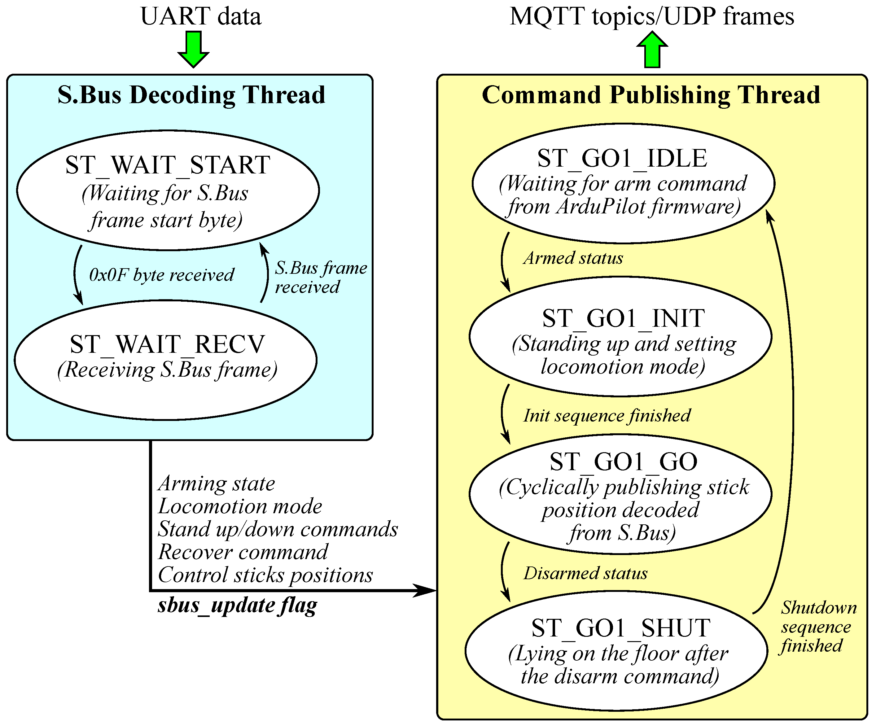
In the proposed design, Cypress IoT SoC CYW43907 is running basic firmware that decodes S.Bus frames received over UART; it extracts control commands from them and retransmits these commands as MQTT topics through Wi-Fi to Go1 (Figure 3). The firmware includes two independently running threads. The first thread waits for the S.Bus start byte (0 × 0f) and receives the following 24 bytes of the S.Bus frame. If the received frame is valid (the last byte is 0 × 00 and both failsafe and frame lost flags are zero), the thread is raising sbus_update flag, simultaneously evaluating the arming state, locomotion mode, stand up/down commands, recover command, and control stick positions from S.Bus channels data. It is worth mentioning that the proposed approach can be directly applied to Unitree Go2 because it has a built-in S.Bus input port.
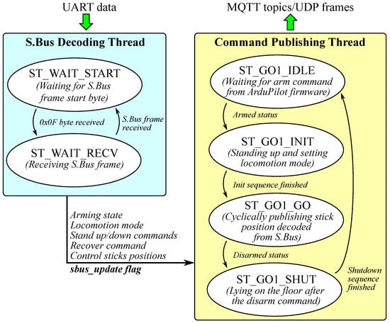
Figure 3.
Cypress IoT SoC CYW43907 application processor firmware structure. Arrow demonsrate signals triggering state machines.
The CYW43907 firmware is created assuming that the channel mapping configured in ArduRover firmware meets the requirements in Table 3. The value ranges in Table 3 are given in the same scale, defined in the ArduRover configuration. At the same time, S.Bus uses another scale compatible with FrSky receivers. Thus, to recover ArduRover output signals right after decoding, S.Bus channels are scaled and shifted according to (1).
where s is the channel value decoded from S.Bus and p is the corresponding value of the ArduRover output channel.

Table 3.
Requirements on ArduRover firmware S.Bus channel mapping.
Any Go1 robot is controlled by two sticks: The left performs forward and side movements, and the right changes the robot’s pitch and yaw. The stick position that will be cyclically transferred to the robot through MQTT is evaluated from the first four channels ( … ) received from ArduRover firmware according to (2). The default values of scale and bias parameters used in (2) are listed in Table 4. The rest of the channels are considered discrete and evaluated according to the last column of Table 3.

Table 4.
Constants defined in the Cypress IoT SoC CYW43907 firmware.
The Command Publishing Thread cyclically monitors sbus_update flag and processes simple state machine introduced in Figure 3. In the ST_GO1_IDLE state, firmware waits until the arming status received from S.Bus changes to “Armed”. Then, the state machine switches to ST_GO1_INIT and sequentially performs “stand up”, “recover after fall”, and “set the chosen locomotion mode” commands.
The time to perform each command is defined by TIME_TO_STAND, TIME_TO_RECOVER, and TIME_TO_CHG_MODE constants, respectively. After the last command is successfully executed, the state machine switches to the ST_GO1_GO state. In this state, the Command Publishing Thread generates an outgoing command («controller/stick» MQTT message in case of Wi-Fi-based control or UDP frame in case of Ethernet-based control) each time it receives the sbus_update flag from the S.Bus decoding thread. If the flag is not received during TIMEOUT_TO_STOP, the thread publishes the “controller/stick” topic with zero , , , and values to stop the robot in case of S.Bus communication loss. If the sbus_update flag will not be received after TIMEOUT_TO_SHUTDOWN (the timeout is greater than TIMEOUT_TO_STOP), the state machine will switch to ST_GO1_SHUT. In the ST_GO1_SHUT state, the robot is forced to lie on the floor to minimize possible damage caused by the possible fall if S.Bus communication is not restored before the battery runs out. Also, the state machine switches to ST_GO1_SHUT from ST_GO1_GO in case the arming status changes to “Disarmed”.
Also, during ST_GO1_GO, discrete control signals (locomotion mode, “stand up/down” commands, and “recover from fall” command) decoded from S.Bus are monitored. In case of their change, a corresponding MQTT topic is published. All the discrete signals are processed sequentially.
The aforementioned firmware serves to demonstrate the proposed hardware and control concept. It is simplified for easier analysis and requires modifications for further use outside research activities. For example, the current version of the firmware does not reconnect if the robot’s Wi-Fi connection is lost.
Possible application areas of the proposed control approach are as follows:
- Research activities focused on the practical applications of quadrupedal robots instead of their locomotion;
- Experimental studies requiring a large number of quadrupedal robots;
- Education in the field of robotics.
It can also be combined with an embedded computer running the Robotic Operation System (ROS) using the MAVROS package [22]. In this case, the ROS software will take advantage of the ready-to-use ArduPilot functionality, including navigation, sensor fusion, data logging, etc.
3. Prototyping
The overall price of the quadrupedal robot controlled by an ArduRover-compatible controller is approximately USD 3000. It includes a Go1 Air robot for USD 2700 and USD 306.36 for additional electronics components and wiring. The complete bill of materials can be found in the Appendix B. We also provide the repository, which includes all design files [23]. The design files include schematic.pdf, which contains a schematic of electrical connections between different parts of the hardware. go1.param contains a full parameter list of the ArduRover firmware used in the current project. The remaining files make up the CYW43907 firmware project for WICED Studio 6.2.
3.1. Assembling of the Prototype
The assembling began with wiring. Wiring between the PixHawk 2.4.8 controller, power module, GNSS receiver, and HC-42 module, used as Bluetooth telemetry, is performed using standard cables according to the schematic provided in design files (schematic.pdf). The GNSS receiver should be connected to the GPS port and HC-42 – to TELEM1 port of the PixHawk controller (A detailed description of other ArduRover hardware configurations and their wiring is provided on the official ArduRover documentation portal (https://ardupilot.org/rover/index.html, (accessed on 1 April 2025)) to be compatible with ArduRover configuration. The input of the power module should be connected to the power supply port on the back of the robot [7,24] using the XT60-XT30 cable listed in Appendix B. To achieve control over Ethernet, an Ethernet cable should be connected to the RJ-45 connectors on CYW943907AEVAL1F and Go1.
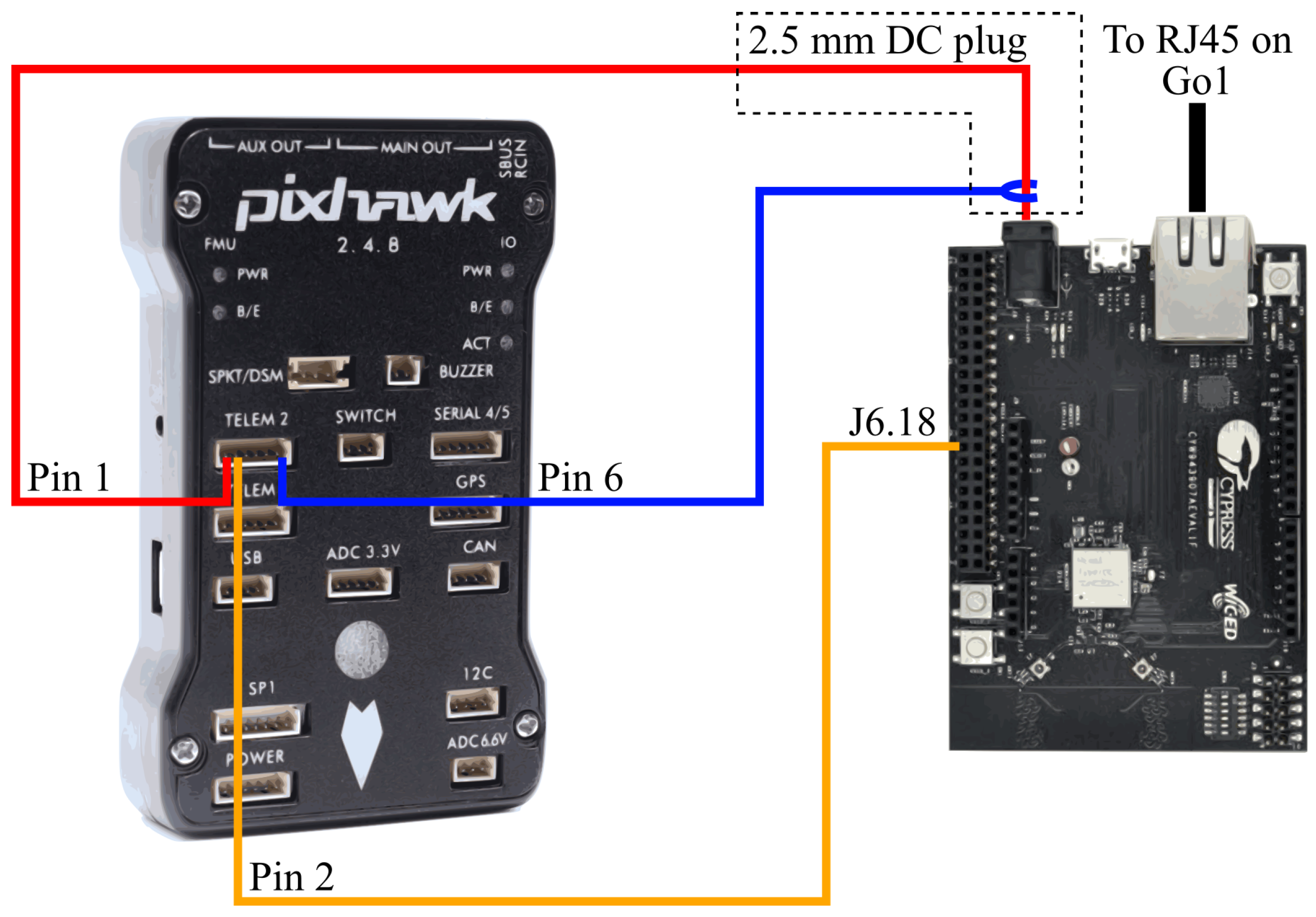
The only custom cable that should be soldered to reproduce the proposed design is the one that connects PixHawk with the CYW943907AEVAL1F development kit (Figure 4). This cable is created by cutting standard telemetry cable delivered with the PixHawk controller, attaching a 2.5 mm power DC plug to pins 1 (+5 V) and 6 (ground), and connecting pin 2 to the breadboard male connector. The last will be connected to pin J6.18 of the CYW943907AEVAL1F (UART receiver’s pin). It is worth mentioning that if it is possible, it is better to solder pin 2 of the telemetry cable directly to the CYW943907AEVAL1F, as breadboard connectors are not reliable enough, especially in conditions of vibrations caused by the run of the quadrupedal robots.
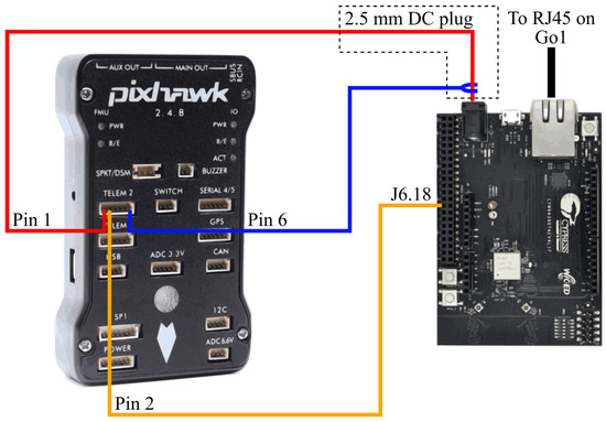
Figure 4.
Wiring between PixHawk 2.4.8 and CYW943907AEVAL1F kit.
For simplicity of reproduction, all electronic components were mounted on the back of the Go1 Air robot with 3M double-sided adhesive tape (Figure 5). The PixHawk controller was mounted on an anti-vibration plate.
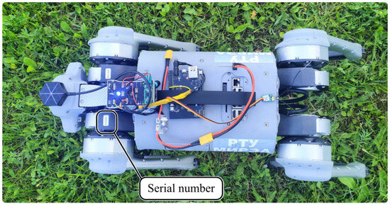
Figure 5.
Location of the components on the robot.
3.2. ArduRover Firmware Configuration
Configuration of ArduRover firmware can be performed using various software tools. We recommend to use Mission Planner (https://ardupilot.org/planner/, (accessed on 1 April 2025)). Instructions on first-time setup presented in official ArduRover documentation (https://ardupilot.org/rover/docs/apmrover-setup.html, (accessed on 1 April 2025)) should be followed to load ArduRover firmware into the new controller. In this project, ArduPilot Rover firmware v.4.2.3 was used. There is no clarity on whether previous or newer versions support all features. The compatibility of the developed firmware with other versions of ArduPilot software is the subject of an investigation.
After firmware is successfully installed on the controller, ArduRover parameters should be set up correctly by using Mission Planner software. This can be performed manually following the guide from the ArduRover documentation (https://ardupilot.org/rover/docs/rover-code-configuration.html, (accessed on 1 April 2025)), or if hardware setup is the same as described in the current paper, parameters can be loaded using go1.param from design files. To load parameters from the file, choose the Config tab in Mission Planner, then choose the Full Parameter List option in the menu, and press the Load from file button. After loading parameters, they should be written into the controller by pressing the “Write Params” button. As some parameters only appear after the others are set into specific values, several write cycles may be required to fully reproduce the parameter list stored in go1.param. After each write cycle, it is recommended to reboot the controller by performing the power sequence (another alternative to reboot the controller is to go to “Setup→Mandatory Hardware→Compass” tab and press the “Reboot” button).
After parameters are successfully loaded, it is necessary to check INS_POS1_X, INS_POS1_Y, INS_POS2_Z, INS_POS2_X, INS_POS2_Y, INS_POS2_Z, INS_POS3_X, INS_POS3_Y, INS_POS3_Z, GPS_POS1_X, GPS_POS1_Y, and GPS_POS1_Z parameters. They define the placement of the controller and GNSS antenna relative to the robot’s center of gravity. A detailed description of these parameters and the coordinate system in which they are defined is provided in the ArduRover documentation (https://ardupilot.org/rover/docs/common-sensor-offset-compensation.html, (accessed on 1 April 2025)).
The main modification introduced into the parameter list to control Go1 Air is the configuration of the TELEM2 to output an inverted S.Bus signal. It requires to set up three parameters:
- Set SERIAL2_PROTOCOL to 15 to change TELEM2 output protocol to S.Bus.
- Set SERIAL2_BAUD to 100 to change TELEM2 baud rate to 100 kbps to meet S.Bus requirements (this parameter will be set automatically after SERIAL2_PROTOCOL will become 15).
- Set BRD_SER2_RTSCTS to 0 to disable hardware flow control on TELEM2 output.
Also, in the provided parameter list, SCR_ENABLE is set to 1, enabling Lua scripts. Lua script will be further used to transmit the arming state into the output S.Bus channel. Finally, the pitch and throttle channels of the RC are swapped using the RCMAP_THROTTLE and RCMAP_PITCH parameters to configure both yaw and throttle to be controlled by the RC’s left stick. This setting depends on the preferences of the operator. It does not affect the rest of the functionality (more information about changing RC channel mapping can be found in ArduRover documentation: https://ardupilot.org/rover/docs/common-rcmap.html, (accessed on 1 April 2025)).
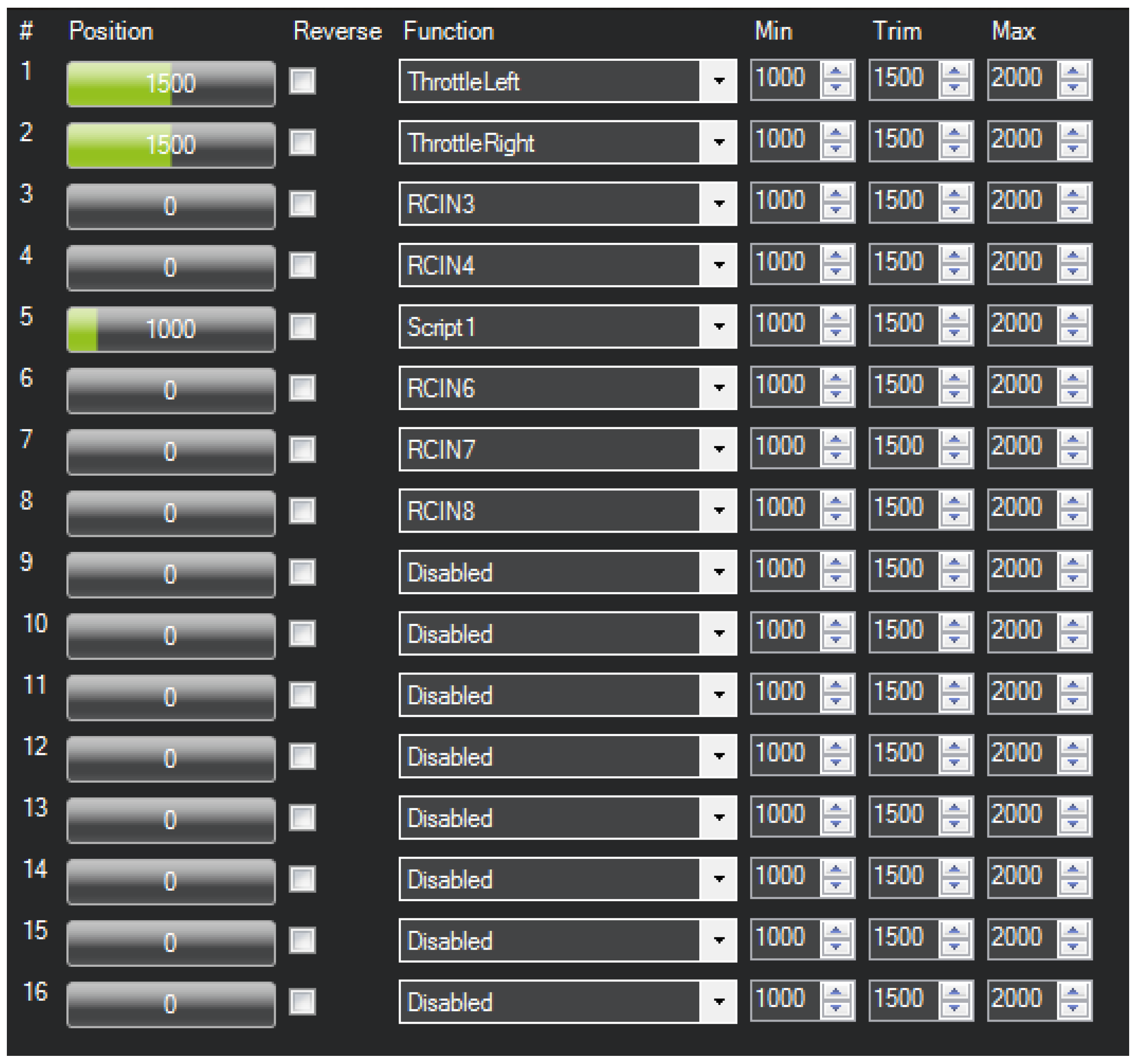
After the main parameters are set, it is necessary to check servo channel mapping. It can be found on the “Setup→Mandatory Hardware→Servo Output” tab. The channels’ functions on this tab should be set as shown in Figure 6.
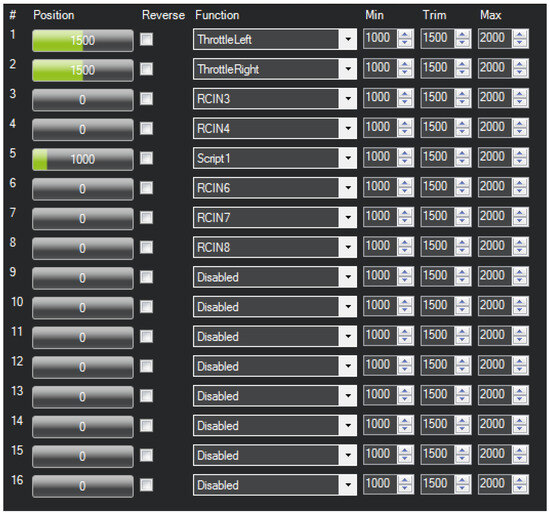
Figure 6.
ArduRover servo output configuration.
Any other variations of the servo output settings may require changes in Cypress IoT SoC CYW43907 firmware.
Then, it is required to configure an RC switch that controls modes. Further, this RC channel will be used to execute autonomous missions and to switch back into manual mode. The identifier of the channel used to change control modes is defined by MODE_CH parameters, while the relationships between its values and specific control modes are defined on the “Setup→Mandatory Hardware→Flight Modes” tab (additional information on configuring ArduRover’s control modes can be found on https://ardupilot.org/rover/docs/common-rc-transmitter-flight-mode-configuration.html, (accessed on 1 April 2025)). In the current project, MODE_CH was set to 9.
The last part of the configuration is uploading Lua script arm_srv.lua into ArduRover’s filesystem. This is carried out using Mission Planner’s “Config→MAVFtp” tab. First, one should create the APM/scripts folder and then, upload arm_srv.lua there from design files (Figure 7) (additional information on uploading Lua scripts can be found on https://ardupilot.org/rover/docs/common-lua-scripts.html, (accessed on 1 April 2025)).

Figure 7.
The location of the Lua script in the ArduRover filesystem.
After all the configuration settings are complete, a reboot of the controller is necessary.
3.3. Cypress IoT SoC CYW43907 Firmware Building
The firmware for Cypress IoT SoC CYW43907 was developed and built using WICED Studio 6.2 (https://www.infineon.com/cms/en/design-support/tools/tools-archive/wiced-studio-archive/, (accessed on 1 April 2025)), but most likely will work with later versions of this Integrated Development Environment (IDE). Before building firmware, it is highly recommended to read CYW943907AEVAL1F’s Evaluation Kit User Guide that describes the basics of software development in WICED Studio (https://www.infineon.com/cms/en/product/evaluation-boards/cyw943907aeval1f/, (accessed on 1 April 2025)).
After WICED Studio is successfully installed, the go1_base folder should be created in 43xxx_Wi-Fi/apps directory in WICED Studio’s “Project Explorer”. The open source code of our solution [23] includes the archives “wired.zip” and “wireless.zip”, containing projects implementing Ethernet/UDP and Wi-Fi/MQTT transport, respectively. Then, one should extract .project,go1_base.c, go1_base.mk, and wifi_config_dct.h design files from the corresponding archive to the created go1_base folder.
Before building firmware, updating the Service Set Identifier (SSID) of the Go1 robot’s access point is necessary. The following line defines SSID:
- #define CLIENT_AP_SSID "Unitree_Go138799A"
The easiest way to find the right SSID is to turn on the Go1 robot and scan Wi-Fi networks for its access point. Usually, it is “Unitee_Go1” followed by a serial number printed on the left forward leg of the robot (Figure 5).
Multiple constants defined in the go1_base.c can be changed to tune different timeouts and thresholds before building. All of them are listed in Table 4.
To build and upload firmware, create a target named “go1_base-CYW943907AEVAL1F download run” in the “Make Target” tab of the WICED Studio and double click on it. Section 3.4 of the CYW943907AEVAL1F’s Evaluation Kit User Guide provides detailed instructions on target creating and firmware building. It should be noted that the above-created target automatically uploads firmware after the build process is over. Thus, CYW943907AEVAL1F must be connected by USB to a PC running WICED Studio before the build starts to avoid errors.
Additional instructions for running the prototype can be found in Appendix C.
4. Experimental Results
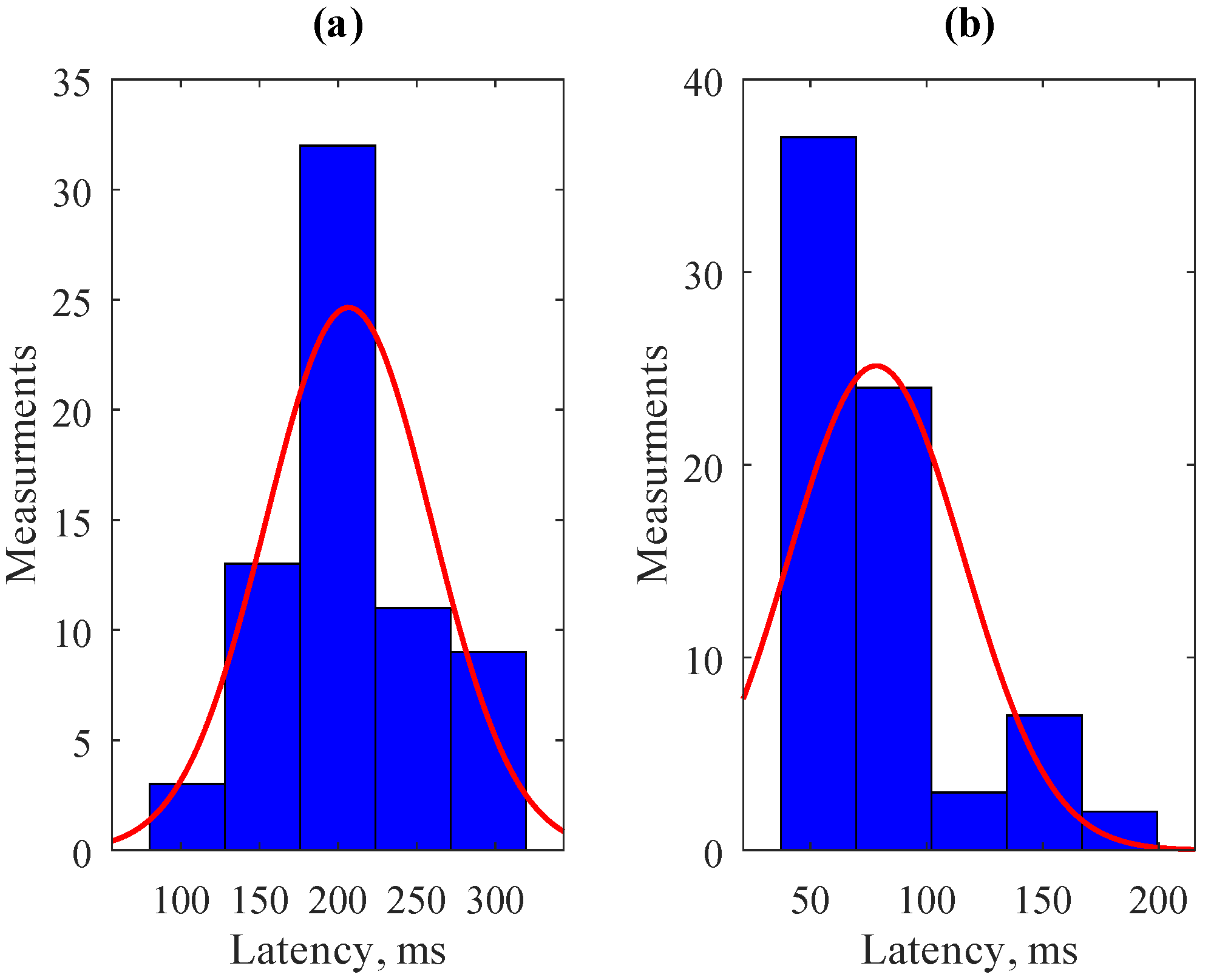
Two experiments were set up to characterize the proposed design and validate its feasibility. The first experiment focused on estimating the latency of the developed S.Bus-WiFi and S.Bus-Ethernet communication channels. During the experiment, multiple yaw angle changes were initiated using RC control. Simultaneously, the actual yaw was measured using the controller’s IMU. Both control inputs and IMU measurements were logged by ArduRover firmware. Then, the collected log data were used to estimate latency between the RC command and the beginning of the IMU Z channel change (Figure 8).
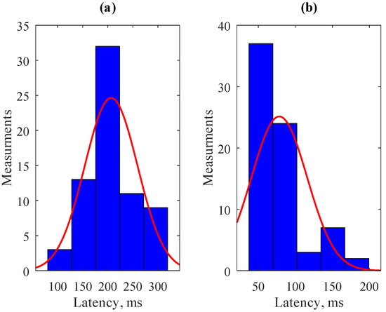
Figure 8.
Histogram of the latency between yaw RC command and beginning of the IMU Z channel change for different communication channels: (a) S.Bus-Wi-Fi; (b) S.Bus-Ethernet.
The average latency introduced by the S.Bus-WiFi communication (Figure 8a) is 206.7 ms, and its standard deviation is below 53 ms. Generally, it is suitable for following the mission route using a GNSS because its data rate is typically ≈5 Hz. As can be seen from (Figure 8b), Ethernet-based communication, which interacts directly with the Go1 robot’s motion controller, has a much lower mean latency of only 78.3 ms and a standard deviation of 37.6 ms. Moreover, the maximum delay of the wired interface is below 200 s, and in most cases, it is ≈50 ms. Thus, Ethernet/UDP control is preferable in cases where a direct connection to the RJ-45 on the back of the robot is possible. Also, Ethernet/UDP provides additional functionality, e.g., the ability to configure step height (see Appendix A). At the same time, the Wi-Fi/MQTT approach can be helpful in cases where additional water/dirt protection is needed.
It is also worth mentioning that measured latencies include not only communication delays introduced by the proposed hardware but also latencies of ArduRover firmware and the Go1 in-built control system. Moreover, quadrupedal kinematics may introduce additional latencies because the robot’s legs should perform a complex motion sequence to change yaw on RC command (at the beginning of this sequence, the yaw may change very slowly or even stay constant). Meanwhile, none of these latencies can be avoided using the proposed hardware, making the above estimations relevant for engineers and researchers to understand the applicability of this approach to their tasks. However, these latencies do not strongly affect the capabilities of the Unitree Go 1 robot in terms of navigation. Since, in this approach, the control commands are sent to the internal dedicated motion controller, which is responsible for leg kinematics, there are no strict requirements in terms of latencies for such high-level commands. If control commands were given directly to the robot’s leg drives with such a delay, this would lead to the inability to maintain balance due to the higher frequency of external disturbances. The only limitation our approach imposes on the robot’s navigation is that the control latencies of Wi-Fi communication ranging from 200–300 ms are not suitable for the routes with sharp turns that should be passed at a high speed. At the same time, considering the maximum speed of Go1, the latencies of Ethernet communication are suitable for most practical applications.
The second experiment aimed to validate the capability of the Go1 Air robot to follow an autonomous mission loaded into the ArduRover controller. The experiment was divided into two tests. In the first test, the test route was 26 m long and included four waypoints. According to [25] RadioLink SE100 GNSS receiver can positions 20 satellites providing 50 cm accuracy. Due to the fact that the experiment was performed in an urban area, the number of simultaneously received satellites ranged from 9 to 12. According to [26], with such a number of tracked satellites, RadioLink SE100 GNSS can provide 2 m positioning accuracy. Thus, the waypoint radius for the test route was set to 2 m. Also, during this experiment, it was mentioned that the Go1 robot often falls while moving in “Walk” mode in outdoor conditions. The problem was solved by switching it to “Run” locomotion mode, which we recommend as the most universal one. During the experiment, the robot consequentially ran along the route three times. After each run, it was returned to the area of the first waypoint in the manual mode. After the experiment was over, ArduRover logs were uploaded and analyzed from the PixHawk controller. This test was performed only for the S.Bus-Wi-fi communication channel.
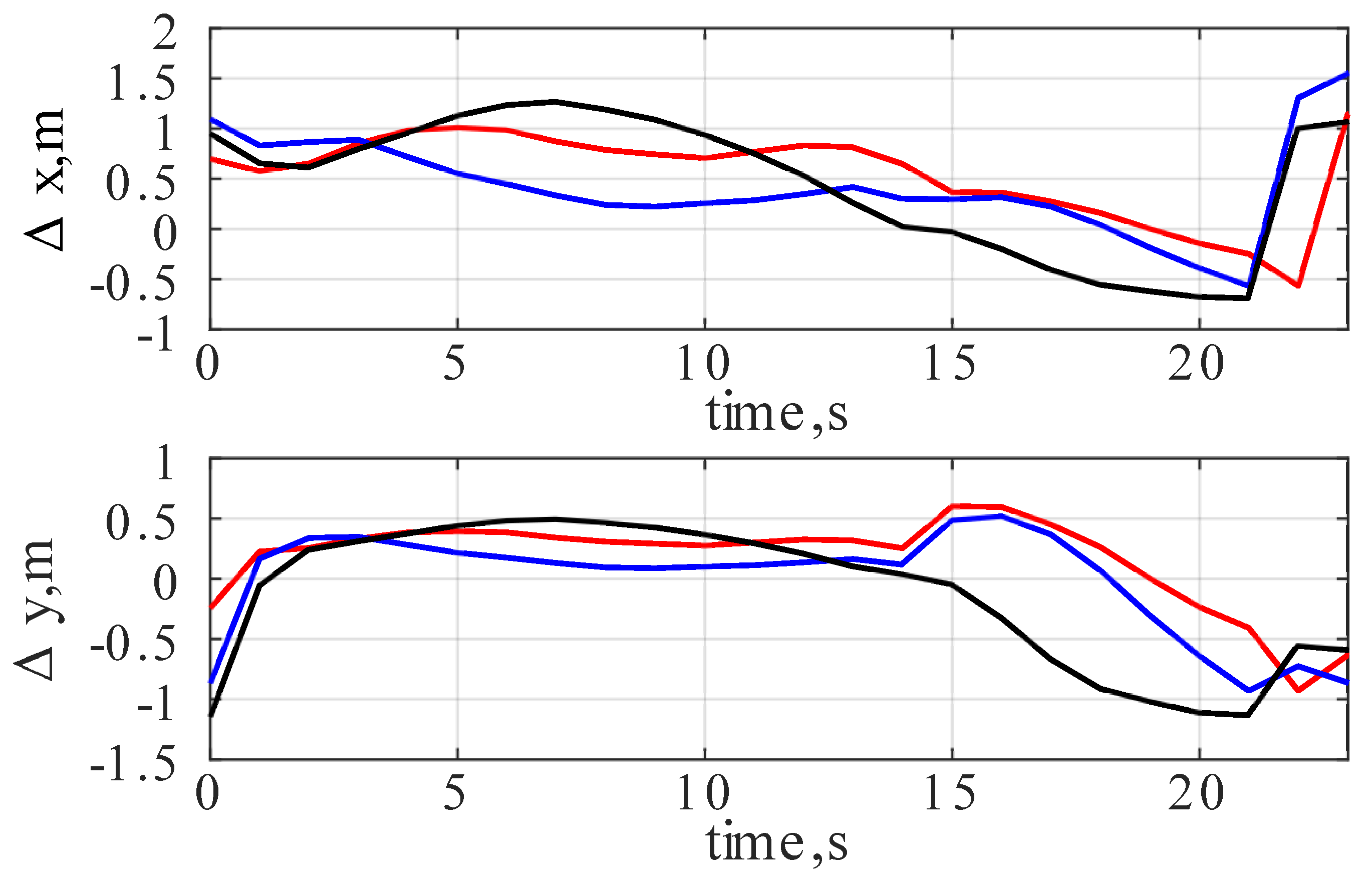
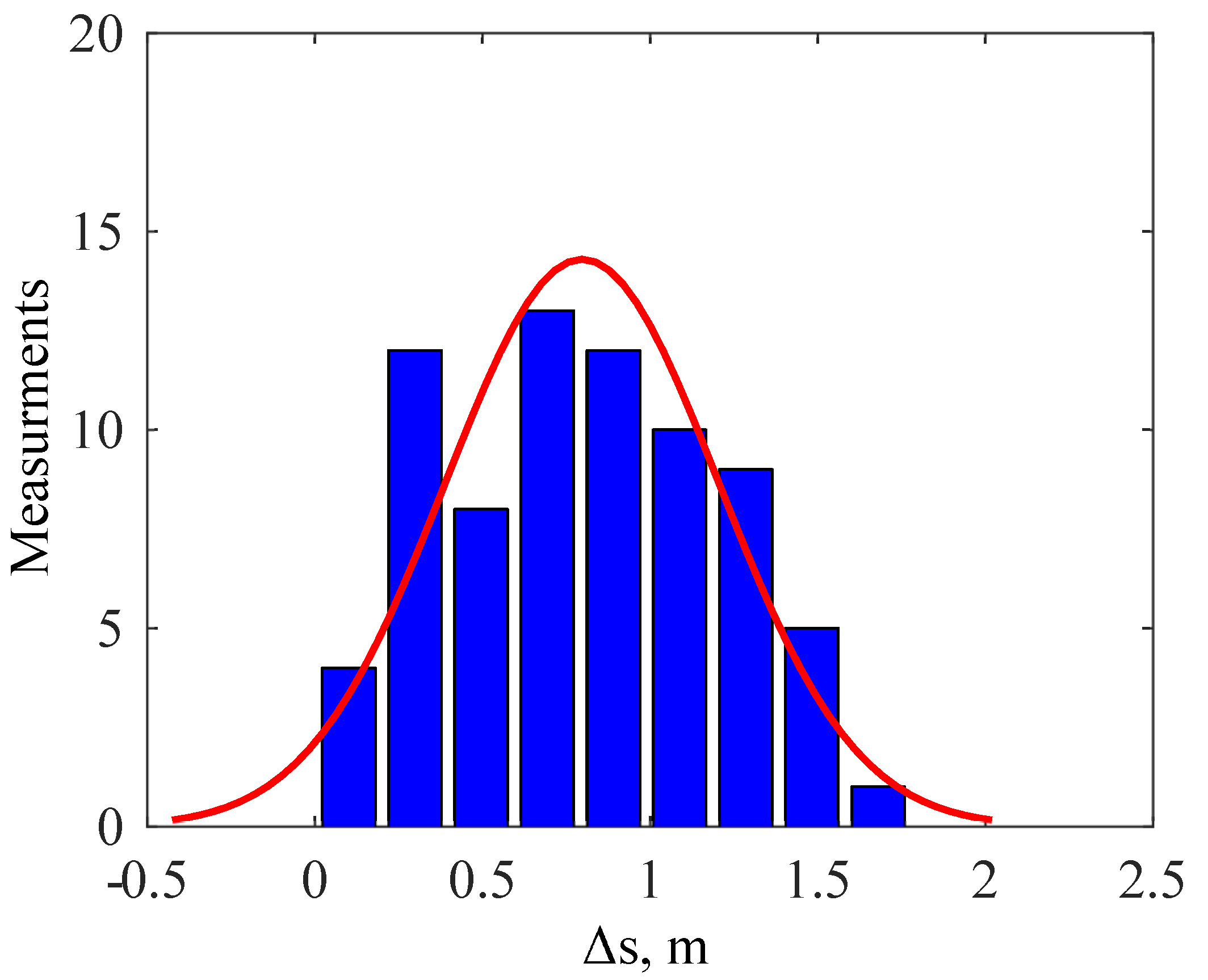
Figure 9 shows the positioning error along the x and y axes ( and , respectively) in the orthogonal coordinate system. Each line color on the figure corresponds to one attempt to run the route. Figure 10 demonstrates a histogram of the distances from the robot to the ideal test route () among all runs performed during the first test of the second experiment.
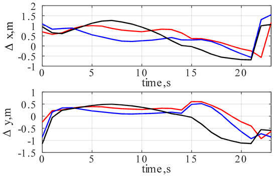
Figure 9.
Positioning error along the x and y axes ( and , respectively) during the first test of the second experiment. Line colors correspond to different attempts to run the test route.
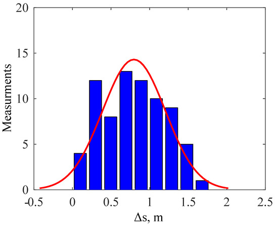
Figure 10.
Histogram of the distances from the robot to the ideal test route () among all runs performed during the first test of the second experiment.
As seen from the Figure 9 and Figure 10, the positioning error never exceeds the defined margin of 2 m. Moreover, the mean distance between the robot and the ideal route was 0.8 m, while the standard deviation of the distance was 0.4 m among all the test runs performed during the experiment. Such precision is typical for ArduRover-based mobile robots that are using GNSS-only navigation without real-time kinematic positioning (RTK).
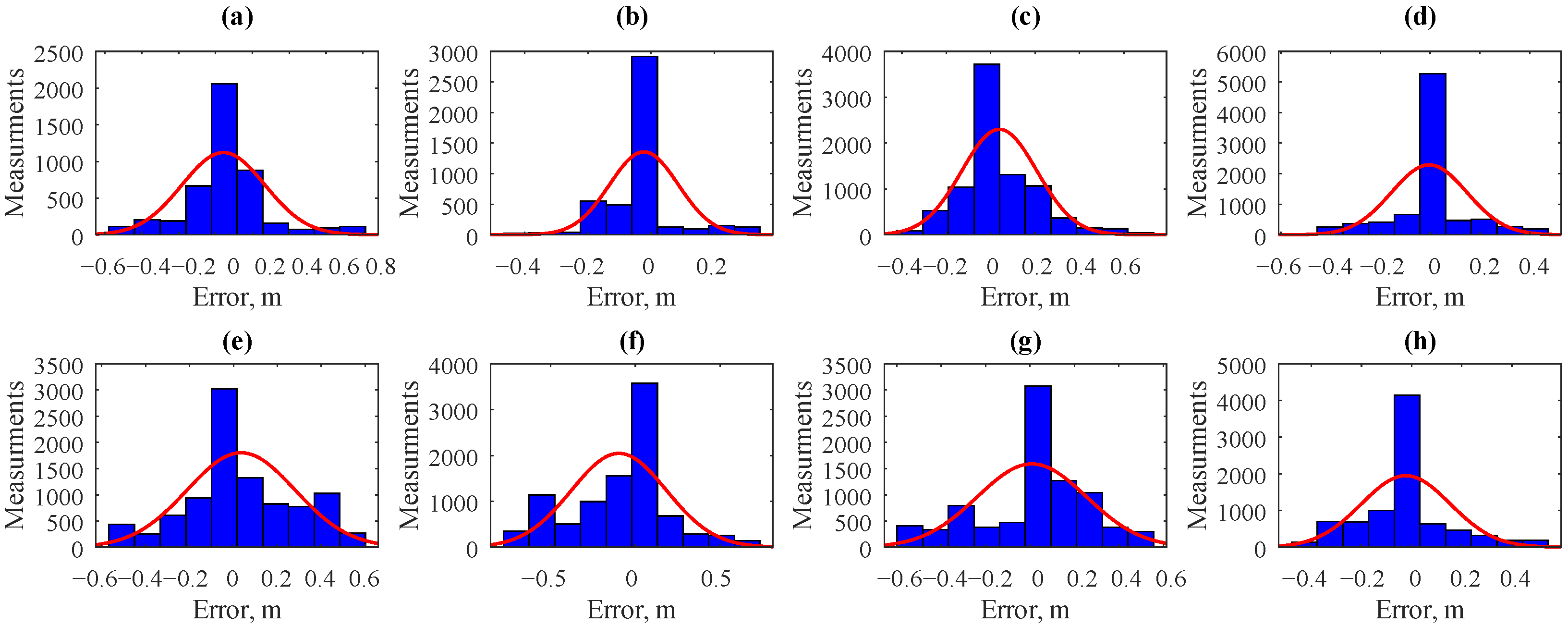
The previous experiment demonstrated that the GPS error is too large, which does not allow to properly compare the influence on the positioning error of S.Bus-Ethernet and S.Bus-WiFi communication channels. That is why we used the MarvelMind navigation system in the second indoor test. Its error is at least 10 times smaller than the one provided by the RadioLink SE100 GNSS receiver. During the test, the robot followed the -shaped route. The test was repeated eight times for the S.Bus Wi-Fi communication channel and another eight times for S.Bus Ethernet. Half of the tests for each communication interface were performed with a walking gait and the other half with a running gait. Figure 11 demonstrates histograms of the positioning error along the x and y axes (x and y, respectively) during the second test of the second experiment.
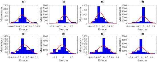
Figure 11.
Histograms of the positioning error along the x and y axes during the second test of the second experiment for different communication channels: (a,b,e,f) S.Bus-Wi-Fi; (c,d,g,h) S.Bus-Ethernet. Gait types: (a–d) walking; (e,f) running. Error type: (a,c,e,g) x; (b,d,f,h) y.
Table 5 summarizes the parameters of the positioning error distribution estimated during the second test of the second experiment. Surprisingly, both types of interfaces between the ArduPilot controller and the quadruped robot lead to similar error values in both walking and running modes. It can be noted that the system equipped with the wired interface provided a slightly lower standard deviation and maximum error, but this difference is much smaller than the ratio between the previously measured interface latencies.

Table 5.
Positioning error distribution’s parameters estimated during the second test of the second experiment.
As seen in Figure 8, the latency of the wired communication channel is usually lower than that of the wireless communication at 150 ms. Thus, 150 ms can be considered as the latency introduced by Wi-Fi and MQTT. It is not easy to distinguish mechanical response latencies introduced by quadruped kinematics from those introduced by the motion controller because the latter runs proprietary firmware. The latencies introduced by the real-time operating system of the Cypress IoT chip running WICED-based firmware were previously investigated in [20] and are less than 5 s. Therefore, they can be considered negligible compared to the others. Thus, switching to a wired communication interface is the proposed design’s main method to reduce latency. At the same time, the results shown in Figure 11 and Table 5 show that due to the relatively low speed of the robot, the difference in the positioning error is comparable for both communication channels and very close to the actual precision of MarvelMind [18]. Thus, the navigation system’s performance and update rate are currently a bottleneck of the proposed design. For example, the position update rate of the MarvelMind navigation system during the experimental studies was below 10 Hz.
Summarizing the experimental results, the hardware proposed in the current paper can successfully control even the cheapest robot from the Unitree Go1 series (Go1 Air) using ArduRover firmware. This capability introduces support for a wide range of sensors and actuators designed for mobile robotics (GNSS receivers, indoor beacons, range finders, gimbals, etc.) and provides autonomous mission execution for only USD ≈300, which is much cheaper than the Go1 Edu version (recommended for autonomous control by Unitree).
Finally, the latency of the proposed control method was estimated, providing engineers and researchers with valuable information required to understand the applicability of this approach to their tasks.
5. Conclusions
This paper proposes an easy-to-implement solution to introduce autonomous navigation and mission execution functionality into the cheapest member of the Unitree Go1 quadruped robot family. The cost of Go1 Air is less than or equal to the cost of open source robot components, including the cost and labor required to build a robot. At the same time, its locomotion capabilities are completely the same as those of the Edu version. Thus, if the research focuses on the application of quadruped robots but not on low-level gait synthesis, the proposed approach saves money and time by going directly to the stage where the robot is controlled like a rover. Moreover, Go2 Air costs only USD 1600 and can even be easily controlled by the proposed method due to its built-in S.Bus interface.
We provide all the necessary source files and comprehensive tutorials to reproduce our approach regarding hardware and software. The experimental studies showed that Wi-Fi control introduces an average latency of 206.7 ms with a standard deviation of less than 53 ms into the ArduPilot control loop. Such latencies are acceptable in many cases because quadruped walking locomotion is implemented by a dedicated controller pre-installed on all Unitree Go1 robots, but it still limits the ability to follow high-speed missions that include sharp turns precisely. At the same time, Wi-Fi control allows the covers on the back of the robot to be closed, increasing protection from environmental factors. At the same time, Ethernet control reduces average latencies to 78.3 ms and provides additional functionality (e.g., the ability to configure step height). Finally, in the range of the standard Go1 speeds, both proposed control interfaces for ArduRover are suitable for most of the practical tasks.
Author Contributions
Conceptualization, N.G. and A.M.R.; methodology, M.P.R. and A.M.R.; software, N.G., Y.Y.T. and A.M.R.; validation, N.G. and Y.Y.T.; formal analysis, N.G. and A.M.R.; investigation, N.G.; resources, M.P.R.; data curation, N.G. and A.M.R.; writing—original draft preparation, N.G. and A.M.R.; writing—review and editing, N.G., M.P.R. and A.M.R.; visualization, N.G.; supervision, M.P.R.; project administration, M.P.R.; funding acquisition, A.M.R. All authors have read and agreed to the published version of the manuscript.
Funding
This research received no external funding.
Institutional Review Board Statement
Not applicable.
Informed Consent Statement
Not applicable.
Data Availability Statement
Data available in a publicly accessible repository.
Conflicts of Interest
The authors declare no conflicts of interest.
Abbreviations
The following abbreviations are used in this manuscript:
| GNSS | Global Navigation Satellite System |
| IDE | Integrated Development Environment |
| IMU | Inertial Measurement Unit |
| IoT | Internet of Things |
| MQTT | Message Queuing Telemetry Transport |
| QoS | Quality of Server |
| RC | Remote Control |
| ROS | Robotic Operation System |
| RTK | Real-time Kinematic Positioning |
| RTL | Return-To-Launch |
| SoC | System-on-a-Chip |
| SSID | Service Set Identifier |
| UART | Universal Asynchronous Receiver/Transmitter |
| UDP | User Datagram Protocol |
Appendix A. Unitree Go1 Ethernet Control Protocol
The Unitree Go1 motion controller has an IP address of 192.168.123.10. It is controlled by UDP unified frames sent on port 8082. Each frame is 171 bytes long (excluding the Ethernet checksum), including 42 bytes of UDP header and 129 bytes of Go1-specific payload. The description of the frame contents is given in Table A1. The same frame is used for both low-level servo drive control and high-level walking locomotion. The fields that are not used for high-level control should be filled with zeros, as shown in Table A1. The X-axis of the velocity is aligned in the direction of the forward movement of the robot body, and the Y-axis is perpendicular to X.

Table A1.
The Go1-specific payload of the UDP control frame.
Table A1.
The Go1-specific payload of the UDP control frame.
| Bytes | Values | Type | Description |
|---|---|---|---|
| 0–1 | 16’hEFFE | uint16 | Predefined header |
| 2–21 | 0 | Array 20×(uint8) | Service fields (works when filled with zeros) |
| 22 | 0—Idle 1—Force stand 2—Walking controlled by 2—Running 3—Climbing | uint8 | Gait type |
| 23 | 0—Idle 1—Walking 2—Running 3—Climbing | uint8 | Gait type |
| 24 | 0—Low speed 1—Medium speed 2—High speed | uint8 | Gait type |
| 25–28 | 0.08–0.12 m | Single | Height on which foots are raised |
| 29–32 | −0.16–0.04 m | Single | Height of the body relative to the default height |
| 33–40 | (0, 0) | 2×(Single) | Position (X,Y) |
| 33–36 | (0, 0) | 2×(Single) | Roll angle |
| 37–40 | (0, 0) | 2×(Single) | Pitch angle |
| 41–44 | (0, 0) | 2×(Single) | Yaw angle |
| 45–48 | −1–1 m/s | Single | X velocity |
| 49–52 | −1–1 m/s | Single | Y velocity |
| 45–48 | 0–3.14 rad/s | Single | Yaw rate |
| 65–128 | 0 | Array 64×(uint8) | Service fields (works when filled with zeros) |
Appendix B. Bill of Materials
The bill of materials is presented in Table A2. The overall price of the quadrupedal robot controlled by an ArduRover-compatible controller is approximately USD 3000. It includes a Go1 Air robot for USD 2700 and USD 306.36 for additional electronics components and wiring. The components listed below should be considered only as a reference example. The ArduPilot ecosystem includes a wide range of compatible components from different vendors with different performances and prices. They would be compatible with the proposed approach as soon they support S.Bus over UART output.
It is worth mentioning that the bill of materials listed below does not include equipment that is not installed on the robot and can be shared between several robots: a remote controller compatible with FrSky XM+ receiver, a Bluetooth Low Energy module for a personal computer (PC) compatible with HC-42 Bluetooth, and a PC to run Mission Planner software to configure and control the ArduRover firmware.

Table A2.
Bill of materials.
Table A2.
Bill of materials.
| Designator | Component | Number | Cost Per Unit, Currency | Total Cost, Currency | Source of Materials | Material Type |
|---|---|---|---|---|---|---|
| Unitree Robotics | Go 1 Air | 1 | USD 2700 | USD 2700 | Unitree Robotics Online Shop | Quadrupedal robot |
| RCToSky | Pixhawk 2.4.8 | 1 | USD 159 | USD 159 | Amazon | ArduPilot compatible flight controller |
| ShareGoo | RC Anti-Vibration Plate | 1 | USD 7.99 | USD 7.99 | Amazon | Anti-Vibration Plate compatible with PixHawk controller |
| Hobbypower | Pixhawk Power Module V1.0 Output BEC 3A XT60 Plug 28 V 90 A 2.4.8 | 1 | USD 13.68 | USD 13.68 | Amazon | ArduPilot compatible flight controller |
| RadioLink | SE100 | 1 | USD 39.99 | USD 39.99 | Amazon | ArduPilot compatible GNSS receiver |
| FrSky | FrSky XM+ 2.4 GHz Micro Receiver | 1 | USD 19.83 | USD 19.83 | RaceDayQuads | RC receiver |
| Guangzhou HC Information Technology | HC-42 | 1 | USD 15.5 | USD 15.5 | Smart Prototyping | Bluetooth Serial Port |
| Infineon Technologies | CYW943907-AEVAL1F | 1 | USD 87.8 | USD 87.8 | Infineon Technologies | Cypress IoT SoC CYW43907 |
| Haoyull | Converter Adapter Female XT60 to Male XT30 | 1 | USD 2.8 | USD 2.8 | Amazon | XT60 to XT30 adapter |
| Jiefei | 2 PCS 5.5 × 2.5 mm 18AWG Right angle 90 degrees DC Power Plug with Cable Black Charging Connector 25 cm | 1 | USD 0.86 | USD 0.86 | AliExpress | 2.5 mm DC power plug |
| California JOS | Breadboard Jumper Wires | 1 | USD 4 | USD 4 | Amazon | Male breadboard wires 2.54 mm |
| Eventronic | 560 PCS Heat Shrink Tubing 2:1, Eventronic | 1 | USD 6 | USD 6 | Amazon | Shrinking cable insulation |
| 3M | Super-Strength Molding Tape | 1 | USD 10.6 | USD 10.6 | Amazon | Double sided adhesive tape |
| Unknown | Pure copper wire CAT6 Flat UTP Ethernet Network Cable RJ45 | 1 | USD 0.75 | USD 0.75 | AliExpress | Patch cord 0.25 m |
Appendix C. Operation Instruction
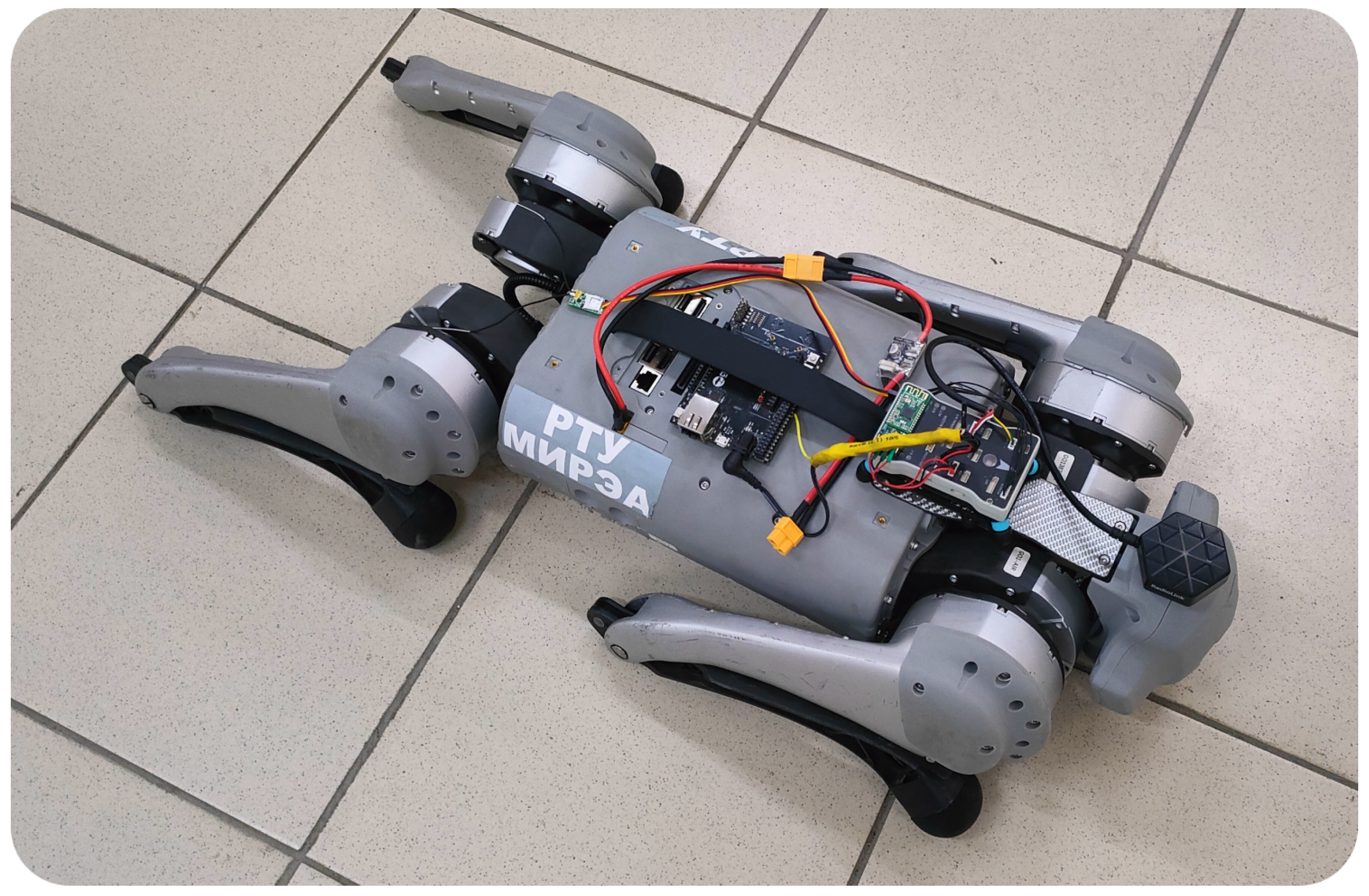
Before starting up, it is important to place the robot in the initial position from which it can stand up (Figure A1). The Go1 user manual [24] describes this position as follows: “Horizontal boot: please make sure that the robot is placed on the leveling ground before starting the machine. The robot’s abdominal support pad should be flat on the ground. The body level is not tilted on the ground. The robot calf is fully stowed, make sure that the robot’s thighs and calves are not pressed by the body, otherwise the robot may fail to boot”.
The turning on sequence for Go1 with the proposed control system is similar to that for the standalone Go1 robots [24]: “short press the power switch once, then press and hold the power switch for more than 2 s to turn on the battery (when the battery is turned on, the indicator light is the green light is always on and the indicator shows the current battery level)”. From our experience, even if the robot is correctly placed in the initial position, it is better to belay it using a handle on its back and prepare to rapidly switch it off in case it fails to stand up.
Turning off is performed using the same sequence of pressing and holding the power switch battery as startup. It should be kept in mind that after switching off, Go1 will immediately turn off all its motors. Thus, it is safer to perform this operation when Go1 is lying on the floor or when the robot is belayed using its handle.
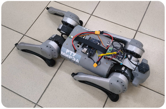
Figure A1.
Initial robot position that should be placed before power up.
Figure A1.
Initial robot position that should be placed before power up.
When the robot is successfully booted and stands on its legs, it is possible to connect to it using Mission Planner software and Bluetooth telemetry. The procedure is identical to that of any other ArduRover-based system (https://ardupilot.org/rover/docs/common-connect-mission-planner-autopilot.html, (accessed on 1 April 2025)).
Before the first startup with a new RC, it is necessary to calibrate its channels. To perform this, open the “Setup→Mandatory Hardware→Radio Calibration” tab and press the “Calibrate Radio” button. Then, it is required to move all sticks and switches to all possible positions and then click the “Ok” button (additional information on RC calibration can be found on https://ardupilot.org/rover/docs/common-radio-control-calibration.html, (accessed on 1 April 2025)).
In each new place where the robot is going to operate, recalibration of the controller’s compass and accelerometers is recommended. This is performed using the “Setup→Mandatory Hardware→Compass” and “Setup→Mandatory Hardware→Accel Calibration” tabs of the mission planner. The detailed description of both procedures is provided in the official ArduPilot documentation (https://ardupilot.org/rover/docs/common-compass-calibration-in-mission-planner.html, https://ardupilot.org/rover/docs/common-accelerometer-calibration.html, (accessed on 1 April 2025)).
After all calibrations, the robot can be operated in Manual (controlled from RC) and Automatic (following preloaded mission) modes. The rest of the ArduRover modes, like Guided or Return-To-Launch (RTL), are also supported.
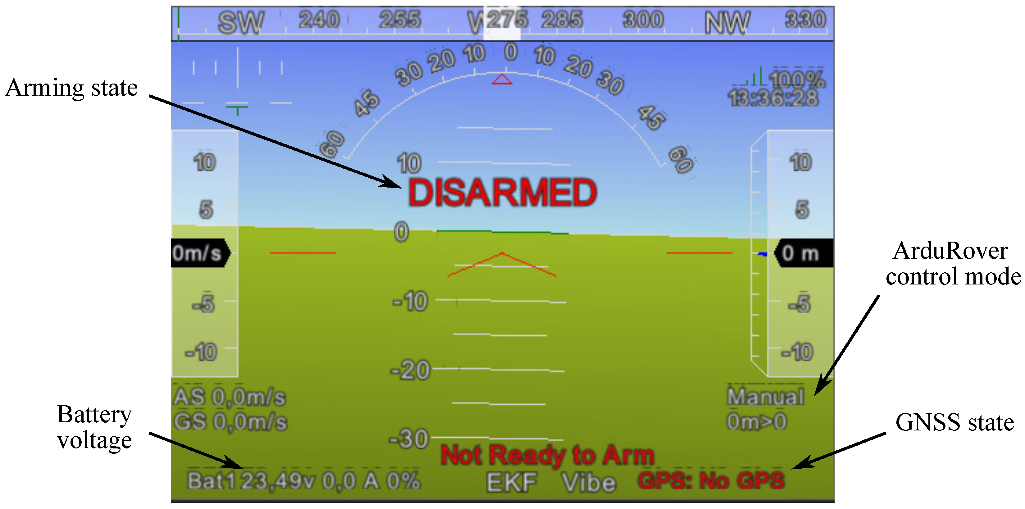
In the left top part of the Mission Planner’s “Data” tab, there is an indicator showing the main system parameters, such as battery voltage, arming state, GNSS state, and current ArduRover control mode (Figure A2). Battery voltage is one of the key parameters that should be monitored. A fully charged battery has a voltage close to 24 V. It is highly recommended to keep the voltage above 21 V to guarantee that the robot will not shut down and fall due to voltage sag. Due to the presence of an ArduRover-compatible power module in the proposed design, it is possible to perform a standard failsafe procedure to disarm the system in case of low battery (https://ardupilot.org/rover/docs/rover-failsafes.html, (accessed on 1 April 2025)).
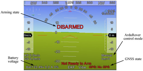
Figure A2.
Main system parameters, shown on the indicator of Mission Planner software.
Figure A2.
Main system parameters, shown on the indicator of Mission Planner software.
After ArduRover indicates that it is ready to arm, it is possible to execute the “Arm” command either using RC control or from the Mission Planner interface using interface (https://ardupilot.org/rover/docs/arming-your-rover.html, (accessed on 1 April 2025)). After the command is executed, first, it will arm the controller running ArduRover firmware. The arming state will be transmitted through S.Bus to CYW943907AEVAL1F, and its firmware will perform an initialization sequence to prepare the Go1 robot for operation.
After the robot is armed, it can be controlled manually using RC. The list of the RC channels configured in ArduRover firmware parameters provided in the design file and the functionality of these channels are listed in Table A3.

Table A3.
Configured RC channels and their functionality.
Table A3.
Configured RC channels and their functionality.
| RC Channel | Type | Function |
|---|---|---|
| 1 | Stick axis | Yaw |
| 2 | Stick axis | Forward movement (throttle) |
| 3 | Stick axis | Side movement |
| 4 | Stick axis | Robot’s body tilt |
| 5 | Two position switch | Arm/disarm |
| 6 | Three position switch | Locomotion mode |
| 7 | Two position switch | Stand up/down |
| 8 | Two position switch | Recover after fall |
| 9 | Two-Six position switch | ArduRover control mode |
The mission should be created in the Mission Planner’s “Plan” tab to run an autonomous mode. Then, it should be loaded into the controller’s memory using the “Write” button on the same tab. After loading the mission, it can be started by switching the ArduRover control mode into “Auto”. More details of mission planning can be found in the official ArduRover documentation (https://ardupilot.org/rover/docs/common-planning-a-mission-with-waypoints-and-events.html, (accessed on 1 April 2025)).
The robot should be disarmed before shutdown. The disarm command can be initiated from RC and the Mission Planner interface. After the disarming procedure, the robot will lie on the floor. Then, it can be powered down by pressing and holding the power switch battery in the same sequence as that for startup.
References
- Hutter, M.; Gehring, C.; Höpflinger, M.A.; Blösch, M.; Siegwart, R. Toward Combining Speed, Efficiency, Versatility, and Robustness in an Autonomous Quadruped. IEEE Trans. Robot. 2014, 30, 1427–1440. [Google Scholar] [CrossRef]
- Biswal, P.; Mohanty, P.K. Development of quadruped walking robots: A review. Ain Shams Eng. J. 2021, 12, 2017–2031. [Google Scholar] [CrossRef]
- Xu, R.W.; Hsieh, K.C.; Chan, U.H.; Cheang, H.U.; Shi, W.K.; Hon, C.T. Analytical review on developing progress of the quadruped robot industry and gaits research. In Proceedings of the 2022 8th International Conference on Automation, Robotics and Applications (ICARA), Prague, Czech Republic, 18–20 February 2022; pp. 1–8. [Google Scholar] [CrossRef]
- Bellicoso, C.D.; Bjelonic, M.; Wellhausen, L.; Holtmann, K.; Günther, F.; Tranzatto, M.; Fankhauser, P.; Hutter, M. Advances in real-world applications for legged robots. J. Field Robot. 2018, 35, 1311–1326. [Google Scholar] [CrossRef]
- Beliakov, M.E.; Diane, S.A.K. Algorithms for the visual analysis of an environment by an autonomous mobile robot for area cleanup. Russ. Technol. J. 2023, 11, 26–35. [Google Scholar] [CrossRef]
- Chae, H.; Ahn, M.S.; Noh, D.; Nam, H.; Hong, D. Ballu2: A safe and affordable buoyancy assisted biped. Front. Robot. AI 2021, 8, 730323. [Google Scholar] [CrossRef] [PubMed]
- MAVProxyUser. HangZhou Yushu Tech Unitree Go1. 2023. Available online: https://github.com/MAVProxyUser/YushuTechUnitreeGo1 (accessed on 1 April 2025).
- Bin4ry. Unitree Go1 Free-Dog SDK Featuring ‘Faux-Level’ Support. 2023. Available online: https://github.com/Bin4ry/free-dog-sdk/tree/main (accessed on 1 April 2025).
- Kim, J.; Kang, T.; Song, D.; Yi, S.J. Design and control of a open-source, low cost, 3D printed dynamic quadruped robot. Appl. Sci. 2021, 11, 3762. [Google Scholar] [CrossRef]
- Bosworth, W.; Kim, S.; Hogan, N. The MIT super mini cheetah: A small, low-cost quadrupedal robot for dynamic locomotion. In Proceedings of the 2015 IEEE International Symposium on Safety, Security, and Rescue Robotics (SSRR), West Lafayette, IN, USA, 18–20 October 2015; pp. 1–8. [Google Scholar] [CrossRef]
- Katz, B.; Di Carlo, J.; Kim, S. Mini cheetah: A platform for pushing the limits of dynamic quadruped control. In Proceedings of the 2019 International Conference on Robotics and Automation (ICRA), Montreal, QC, Canada, 20–24 May 2019; pp. 6295–6301. [Google Scholar]
- Kau, N. Stanford pupper: A low-cost agile quadruped robot for benchmarking and education. arXiv 2021, arXiv:2110.00736. [Google Scholar]
- Raber, G.T.; Schill, S.R. Reef Rover: A low-cost small autonomous unmanned surface vehicle (USV) for mapping and monitoring coral reefs. Drones 2019, 3, 38. [Google Scholar] [CrossRef]
- Romanov, A.M. A review on control systems hardware and software for robots of various scale and purpose. Part 2. Service robotics. Russ. Technol. J. 2020, 7, 68–86. [Google Scholar] [CrossRef]
- Zaman, A.M.; Seo, J. Development of an Autonomous Flying Excavator. Eng. Proc. 2022, 24, 4. [Google Scholar] [CrossRef]
- Oyelami, A.T.; Bamgbose, O.M.; Akintunlaji, O.A. Mission-Planner Mapped Autonomous Robotic Lawn Mower. J. Eur. Syst. Autom. 2023, 56, 253–258. [Google Scholar] [CrossRef]
- Liardon, J.L.; Barry, D.A. Adaptable imaging package for remote vehicles. HardwareX 2017, 2, 1–12. [Google Scholar] [CrossRef]
- Romanov, A.M.; Romanov, M.P.; Morozov, A.A.; Slepynina, E.A. A navigation system for intelligent mobile robots. In Proceedings of the 2019 IEEE Conference of Russian Young Researchers in Electrical and Electronic Engineering (EIConRus), Saint Petersburg and Moscow, Russia, 28–31 January 2019; pp. 652–656. [Google Scholar] [CrossRef]
- Schulz, M.; Wegemer, D.; Hollick, M. Nexmon: The C-Based Firmware Patching Framework. 2017. Available online: https://nexmon.org (accessed on 1 April 2025).
- Romanov, A.M.; Gringoli, F.; Alkhouri, K.; Tripolskiy, P.E.; Sikora, A. Enabling Time-Synchronized Hybrid Networks with Low-Cost IoT Modules. IEEE Internet Things J. 2023, 10, 9966–9978. [Google Scholar] [CrossRef]
- Pizarro, A.B.; Beltrán, J.P.; Cominelli, M.; Gringoli, F.; Widmer, J. Accurate ubiquitous localization with off-the-shelf IEEE 802.11ac devices. In Proceedings of the 19th Annual International Conference on Mobile Systems, Applications, and Services, Online, 24 June–2 July 2021; pp. 241–254. [Google Scholar] [CrossRef]
- Simon, G.A.; Moore, J.M.; Clark, A.J.; McKinley, P.K. Evo-ROS: Integrating evolution and the robot operating system. In Proceedings of the Genetic and Evolutionary Computation Conference Companion, Kyoto, Japan, 15–19 July 2018; pp. 1386–1393. [Google Scholar]
- Gyrichidi, N.; Romanov, M.; Tsepkin, Y.; Romanov, A. Enabling Navigation and Mission-Based Control on a Low-Cost Unitree Go1 Air Quadrupedal Robot. 2025. Available online: https://zenodo.org/records/15021612 (accessed on 1 April 2025).
- Unitree. Go1 User Manual v.14, 2021. Available online: https://github.com/MAVProxyUser/YushuTechUnitreeGo1/blob/main/Go1%20User%20Manual%201.4.pdf (accessed on 1 April 2025).
- Noori, R.; Dahnil, D.P. The Effects of speed and altitude on wireless air pollution measurements using hexacopter drone. Int. J. Adv. Comput. Sci. Appl. 2020, 11, 268–276. [Google Scholar] [CrossRef]
- Khyasudeen, M.F.; Buniyamin, N.; Azzuhri, S.R.; Noor, M.B.M.; Bakar, M.H.B.A.; Rahman, M.F.A.; Kamel, N.I.; Shariffuddin, A.; Amiri, I.S. The development of a GPS-based autonomous quadcopter towards precision landing on moving platform. Int. J. Veh. Auton. Syst. 2022, 16, 108–126. [Google Scholar] [CrossRef]
Disclaimer/Publisher’s Note: The statements, opinions and data contained in all publications are solely those of the individual author(s) and contributor(s) and not of MDPI and/or the editor(s). MDPI and/or the editor(s) disclaim responsibility for any injury to people or property resulting from any ideas, methods, instructions or products referred to in the content. |
© 2025 by the authors. Licensee MDPI, Basel, Switzerland. This article is an open access article distributed under the terms and conditions of the Creative Commons Attribution (CC BY) license (https://creativecommons.org/licenses/by/4.0/).

