Article

Mitigating Settlement and Enhancing Bearing Capacity of Adjacent Strip Footings Using Sheet Pile Walls: An Experimental Approach

by
Ali M. Basha
1,
Ahmed Yousry Akal
2,* and
Mohamed H. Zakaria
1,*
1
Civil Engineering Department, Faculty of Engineering, Kafrelsheikh University, Kafrelsheikh City 33511, Egypt
2
Civil Engineering Department, Higher Institute of Engineering and Technology—Kafr El Sheikh, Kafrelsheikh City 33511, Egypt
*
Authors to whom correspondence should be addressed.
Infrastructures 2025, 10(4), 83; https://doi.org/10.3390/infrastructures10040083
Submission received: 14 February 2025 / Revised: 28 March 2025 / Accepted: 31 March 2025 / Published: 2 April 2025
(This article belongs to the Section Infrastructures and Structural Engineering)

Abstract

:
In construction, closely spaced footings cause stress interactions that impact bearing capacity, settlement, and stability. This study experimentally evaluates the role of sheet pile walls (SPWs) in improving the performance of two adjacent strip footings—an existing footing and a newly placed footing—on sandy soil. The influence of SPW penetration depth (Ls) and center-to-center spacing between footings (X) on settlement and bearing resistance under vertical loads was investigated. Experiments were conducted in a large-scale soil tank (330 × 30 cm, depth 210 cm), with X ranging from 300 mm to 1000 mm and SPW lengths varying from 0 mm to 1500 mm. The results show that SPWs significantly enhance foundation performance by reducing settlement and increasing bearing capacity. When Ls/B = 6, the settlement of the new footing (F1) decreases by 48%, while the existing footing (F2) sees reductions of 47%, 67%, and 77% at Ls/B = 3, 4, and 5, respectively, under 500 kN/m2 stress. The bearing capacity of F1 increases by 53% when X = 300 mm, demonstrating strong interference effects. Conversely, the F2 settlement increases as X decreases, with a 96% rise at X = 300 mm, but it stabilizes at Ls/B = 5. SPWs also shift failure from general shear to punching shear, modifying soil–structure interaction. These findings highlight the effectiveness of SPWs in mitigating settlement, enhancing load-bearing capacity, and optimizing foundation design in closely spaced footing systems. The results suggest that an SPW length-to-footing width ratio (Ls/B) between 4 and 5 is optimal for minimizing settlement and improving stability, with only a slight difference in effectiveness between these two ratios.

1. Introduction

Due to population expansion and land scarcity, structures are currently built close to each other. Differences in stresses of adjacent or nearby shallow foundations design can cause an interference problem. Interference issues in shallow foundation design have been the subject of investigation for decades, with numerous researchers, including [1,2,3], contributing to the understanding of this phenomenon. The stability of nearby buildings is compromised when heavy structures are constructed in close proximity, as the additional surcharge can induce uneven settlement, posing a significant risk to structural integrity [4]. The numerous complaints and appeals each year about disruptions caused by new constructions in densely populated areas reflect public dissatisfaction with current design and construction practices. This underscores the lack of consideration for existing structures and community impact when planning new buildings [1]. Investigating the impact of adjacency and possible mitigation strategies on settlement and bearing capacity thus seems to be crucial. Settlement of nearby foundations was found to be much higher compared with single isolated footing [5]. The effect of interference on the bearing stress and stress bulb under the footings was investigated by Selvadurai and Rabbaa [6]. Experimental results implied that with the decrease in the distance between the foundation the stress bulb became asymmetrical. Moreover, the effect of interference on the bearing capacity of two near footing rested on dense sand above a soft clay layer showed that bearing capacity increased with the increase in the distance between the footing [7,8].
Using a sheet pile wall is a key solution to mitigating interference effects between adjacent footings, as stated by Basha et al. [9,10]. Ozpolat and Aksoy [11] experimentally investigated the influence of sheet pile wall (SPW) separation from shallow foundations on bearing capacity. They examined parameters such as foundation length (Ls), SPW penetration depth (Hp), and internal sheet pile spacing (Ls), concluding that L had the greatest impact on ultimate bearing capacity (qne) and maximum settlement (δmax). Their findings showed that increasing Hp improved qne while reducing δmax. Jayamohan et al. [12] numerically analyzed additional settlements induced by adjacent footings, emphasizing that increasing footing separation reduces foundation interactions and improves stability. Similarly, Basha and Elsiragy [13] investigated the effects of driving SPWs in sandy soils, concluding that greater embedment depth and hammer efficiency significantly impact excess pore water pressure and settlement. Experimental centrifuge modeling by Salamatpoor et al. [14] demonstrated that interference between old and new foundations increased the new footing’s bearing capacity but caused higher settlement and tilting in the existing footing. They found that decreasing the spacing-to-footing width ratio significantly affected settlement. Alwalan [15] also reported that reduced center-to-center distances between footings in sandy soil intensify interference effects. Denver and Kellezi [16] studied the impact of earth pressure from surrounding footings on SPWs in freestanding and anchored conditions, developing an analytical approach to predict additional pressure exerted on the wall. In numerical studies, Debnath and Pal [17] and Singh and Chatterjee [18] found that cantilever SPWs near excavations experience maximum lateral deformations and bending moments, highlighting the importance of embedment depth in reducing settlement and tilts.
The maximum bearing capacity of footings increased as spacing decreased, becoming equivalent to a single isolated footing at extreme distances [19,20]. Mowafe et al. [21] found that foundation settlement reduced as the depth ratio increased, disappearing when spacing reached 1.5 times the excavation depth. Footing type significantly influenced load effects on existing foundations [1], while embedment depth played a crucial role in minimizing additional settlements and tilts by redistributing stress to lower soil layers.
The optimal spacing between footings maximizes bearing capacity [22]. Das et al. [23] noted that widely spaced footings behave as isolated foundations, whereas closely spaced footings experience a blocking or arching effect, where the soil between them forms an inverted arch. When footings touch, they act as a single foundation with twice the original width, eliminating the arching effect. Despite extensive research, there is a lack of studies on how new foundations impact existing ones. This study investigates the negative effects of a newly constructed strip footing on the load–settlement behavior of an adjacent footing on sandy soil. It also examines the effectiveness of sheet pile walls (SPWs) in mitigating settlement and improving foundation performance. Through experimental tests, this study evaluates how footing spacing (X) and SPW length (Ls) influence additional settlement, providing insights for optimizing foundation design in densely built environments.

The Failure Mechanism and Sheet Pile Wall Effects

This study examines how closely spaced footings interact and influence the bearing capacity of strip footings on sandy soil, with and without sheet piles. Stuart [3] experimentally analyzed the effect of adjacent foundations on cohesionless soil and developed a theoretical equation based on test results and prior studies by Stuart and Hanna [24]. This study assumed uniform soil conditions and applied Terzaghi’s [25] rupture geometry to the failure mechanism. It was concluded that as the center-to-center distance between footings decreases, the ultimate bearing capacity may be reduced due to interference from overlapping failure surfaces in the Rankine passive zone.
Four failure modes for the surface of cohesionless soil under two adjacent foundations were presented by Das [26] and Stuart [3] as shown in Figure 1. For the first mode, the center-to-center distance between the two footings is x > x1, x1 is the minimum distance at which there is no interference for the passive zones shown in Figure 1a. In this mode, Terzaghi’s equation (see Equation (1)), (for cohesionless soil, c = 0), can be used to determine the maximum bearing capacity of each continuous foundation. The second mode occurs when the passive zone interpenetrates (x = x2 < x1) as illustrated in Figure 1b. In this mode, the vertical stress under the footing remains the same as in the first mode so Equation (1) will still be valid to determine qu. However, compared to the scenario of an isolated foundation, the foundation settling at the ultimate load will alter. The third mode takes place when the passive zones under the footings decrease due to the interaction as Figure 1c includes (where x = x3 < x2). Efficiency factors ( ε q and ε q γ ) were added to Equation (1) to represent the reduction in the passive resistance as presented in Equation (2) (source: Das [26]).
q u = q N q + 1 2 γ B N γ
q u = q N q ε q + 1 2 γ B N γ ε q γ
Finally, the fourth mode occurs when x = x4 < x3 as shown in Figure 1d at which the soil between the two footings forms an inverted arch and travels down under the footings due to the applied loads. The inverted arch disappears when the two footings come into contact and in this case, Equation (1) can be employed to estimate qu for footing with width 2B.
Despite extensive research on the interference effects of closely spaced foundations, most studies have primarily focused on the bearing capacity and settlement behavior of adjacent footings without considering practical mitigation strategies. The impact of newly constructed foundations on the performance of existing footings, particularly in sandy soils, remains insufficiently explored. Moreover, while sheet pile walls (SPWs) have been recognized as an effective ground improvement technique, their role in minimizing settlement and enhancing the bearing capacity of adjacent footings has not been thoroughly investigated. This study aims to bridge this gap by experimentally evaluating the influence of footing spacing (X) and SPW length (Ls) on the interaction between adjacent strip footings. The findings of this research can provide valuable insights into optimizing foundation design in densely built environments.

2. The Experimental Program

2.1. Scale Selection and Scale Effects

The selection of the experimental size was based on three key criteria. First, geometric similarity was maintained using a 1:4 scale ratio, ensuring that all dimensions, including the footing width and sheet pile length, were proportionally scaled to reflect the prototype conditions accurately. Second, stress distribution and load transfer were considered, with the model dimensions chosen to replicate the real-scale stress behavior of strip footings on sandy soil while maintaining proportional settlement responses. Third, laboratory feasibility was ensured by designing an experimental setup that allowed practical implementation, repeatability, and precise data collection without compromising realism.
The geometrical properties of the prototype used for modeling in this study involved strip footings with a fixed width of 1 m and infinite length and a sheet pile with prototype dimensions ranging from 3.0 m to 6.0 m. The model dimensions were scaled down by a 1:4 scale ratio to ensure the experiment could be conducted efficiently in the laboratory while maintaining similitude. Following Buckingham’s Pi Theorem, the model footings were designed with dimensions of 250 mm in width, 40 mm in thickness, and a length of 300 mm, with the sheet pile length varying between 750 mm and 1500 mm, depending on the test configuration. The soil tank dimensions were scaled appropriately to avoid boundary effects, with internal dimensions of 330 × 30 cm and a depth of 210 cm. The similarity law and constants for the model are provided in Table 1, reflecting the scaling factors between the prototype and model, ensuring that the experimental results can be accurately extrapolated to real-world applications.
Specific measures were taken in the experimental design to eliminate scale and boundary effects. The soil tank dimensions (330 cm × 30 cm × 210 cm) were selected to be sufficiently large to prevent boundary interference that could affect bearing capacity, settlement, and stress distribution. The tank area (9900 cm2) is approximately 132 times larger than the model footing area (75 cm2, 250 mm × 300 mm), ensuring that stress bulbs beneath the footing do not interact with the container walls. This prevents lateral boundary effects and allows realistic load transfer. The tank depth (210 cm) was chosen to be at least four times the depth of the modeled soil (based on the 1:4 scale ratio), ensuring sufficient settlement space and avoiding bottom boundary constraints. Although the model soil volume was scaled down by a factor of 64, the large tank dimensions ensured that stress distribution beneath the footing remained representative of full-scale behavior. Furthermore, similitude laws based on Buckingham’s Pi Theorem were applied to maintain static and dynamic similarity between the model and prototype. Parameters such as stress distribution, strain, deformation, and load transfer followed the similarity constants provided in Table 1, allowing reliable extrapolation of results to real-world conditions. The selected dimensions ensured minimal scale effects, making the model test a valid and reliable representation of full-scale strip footing behavior.
Although the model used in this study is a large-scale model, it is essential to acknowledge certain limitations related to scale effects and stress levels. The experiments were conducted at 1 g, and while the geometric similitude between the model and the prototype was maintained using a 1:4 scale ratio, the model’s stress levels were inherently lower than those in real-world, full-scale conditions. The reduced stress levels in the laboratory model, a characteristic of large-scale testing, could influence the magnitude of settlements and the stress distribution beneath the footing. While the experiment was designed to replicate real-world behavior closely, the lower stress levels may have underestimated certain ground displacements and foundation responses, particularly in highly stressed environments. The results, therefore, are valid for the scaled conditions and represent the relative effects of parameters like footing configuration, sheet pile length, and soil density. However, it is important to recognize that extrapolating these results directly to full-scale structures requires consideration of stress-related scale effects, which could lead to differences in the absolute values of settlements and stresses observed. Despite these limitations, the trends observed in the large-scale model—such as the impact of soil density, footing design, and sheet pile depth—provide meaningful insights into the general behavior of the system and can be useful for preliminary design and analysis.

2.2. Experimental Setup and Test Parameters

The test setup and parameters are shown in Figure 2. The experimental program and a summary of the investigated parameters are presented in Table 2. The dimensions of the footings are 250 (width) × 300 (length) × 40 (thickness) mm. Footings are fabricated from steel. The sheet pile is built of steel with a 3 mm thickness and ranges in length from 750 to 1500 mm. In this study, the thickness of the sheet pile wall (SPW) was fixed at 3 mm to isolate the effects of penetration depth (Ls) and installation position on foundation performance. This choice was made to ensure that changes in performance could be attributed solely to these parameters, without introducing additional complexities from variations in bending stiffness. While bending stiffness is a significant factor in soil–structure interaction, particularly for retaining walls and embedded structures subjected to lateral earth pressures, its influence in this setup is expected to be minimal. The SPW in this study is fully embedded in the soil and primarily subjected to bearing pressures from adjacent footings rather than significant lateral soil pressures. This configuration differs from conventional retaining walls, where bending stiffness plays a dominant role in structural stability. Therefore, the selected thickness ensures experimental control while maintaining structural integrity under the applied loading conditions. Although bending stiffness plays a key role in soil–wall interaction, as demonstrated in previous studies (e.g., [27]), its significance in this study is reduced due to the symmetrical loading conditions. Unlike retaining walls, where bending stiffness affects deformations and earth pressure distribution, the SPW in this study is primarily subjected to vertical bearing forces rather than lateral soil pressures. However, variations in bending stiffness may still influence local deformations and stress distributions. Future studies should examine the effects of SPW thickness and material properties on the interaction between the SPW and the surrounding soil, especially under varying load conditions. Wall roughness also plays an important role in the interaction between the structure and the surrounding soil, influencing frictional resistance and load transfer mechanisms. Previous studies (e.g., [27]) have emphasized the effect of wall roughness on modifying stress distributions and soil behavior. Although wall roughness was not explicitly varied in this study, its potential impact on SPW performance has been acknowledged. Future research should explore the effects of surface roughness on soil–structure interaction. Such investigations would complement the current findings on penetration depth and installation position, providing a more comprehensive understanding of the factors affecting SPW performance in foundation systems.
An identification system distinguishes between the footings during the tests and the analysis. Every strip footing has two letters followed by two numbers as an identification number. FN refers to the new strip footing, while FO stands for the old strip footing. The first number is the internal distance between the two strip footings, center to center (x) in centimeters. Yet, the second number refers to the sheet pile length (Ls).

2.3. Soil Preparation and Characterization

The geotechnical properties of the sand utilized in this investigation are listed in Table 3; each test is repeated three times, and the mean values are reported. The sand used in this study is classified as poorly graded (SP) by the Unified Soil Classification System (USCS). The jar method is considered to calculate the sand particles’ specific gravities. The dry sieving method is used to determine the particle size distribution [28]. At maximum and minimum densities, a direct shear test is performed to evaluate the internal friction angle of the employed sand [29].

2.4. Test Tank and Loading Procedure

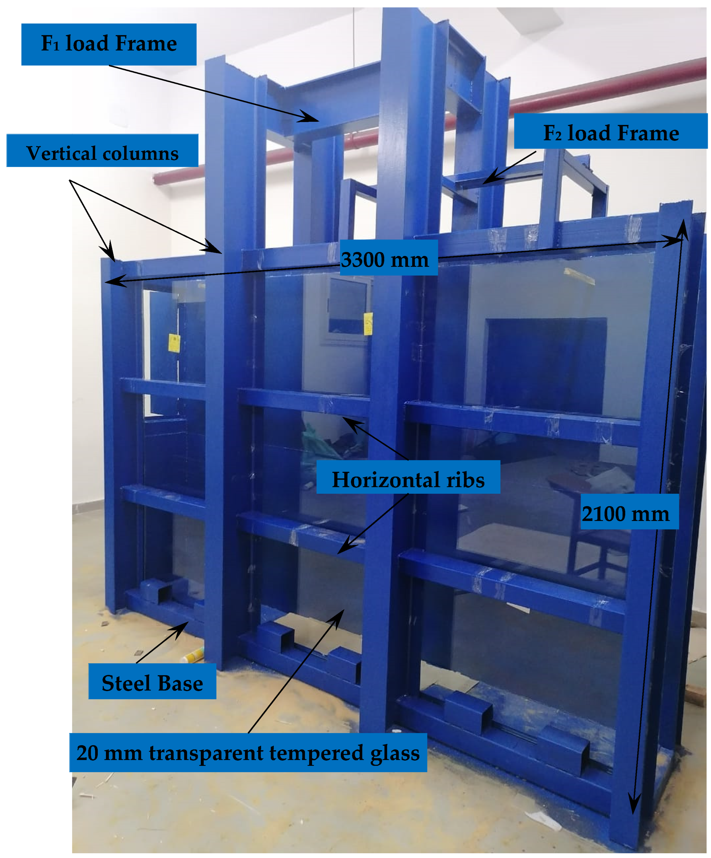
The soil tank is a rectangular steel container with internal measurements of 330 × 30 mm and a depth of 210 cm. Hence, the soil tank’s dimensions are sufficient to minimize how the boundary conditions affected the performance of the footings. The sides of the soil tank are reinforced with 110 × 80 × 6.0 mm horizontal steel hollow sections and 10 mm-thick steel plates to prevent any lateral distortion. The dirt tank is resting on a sturdy steel platform that is placed horizontally on the lab floor. Using a spirit level, the test setup is leveled both vertically and horizontally. One side of the tank is made of 20 mm-thick transparent tempered glass to visually monitor the movement of the soil and the wall. Figure 3 illustrates the soil tank in details.

2.5. Procedure for the Testing Model’s Operation

To achieve the desired relative density, soil samples are prepared in layers, with each layer having a specified weight and being compacted to a predetermined height within the soil tank. The unit weight of the prepared sample is found to be uniform with depth, maintaining an accuracy of ±0.1 kN/m3. Samples are prepared according to Aamer et al. [30], Azzam and Elwakil [31], and Nasr and Azzam [32].
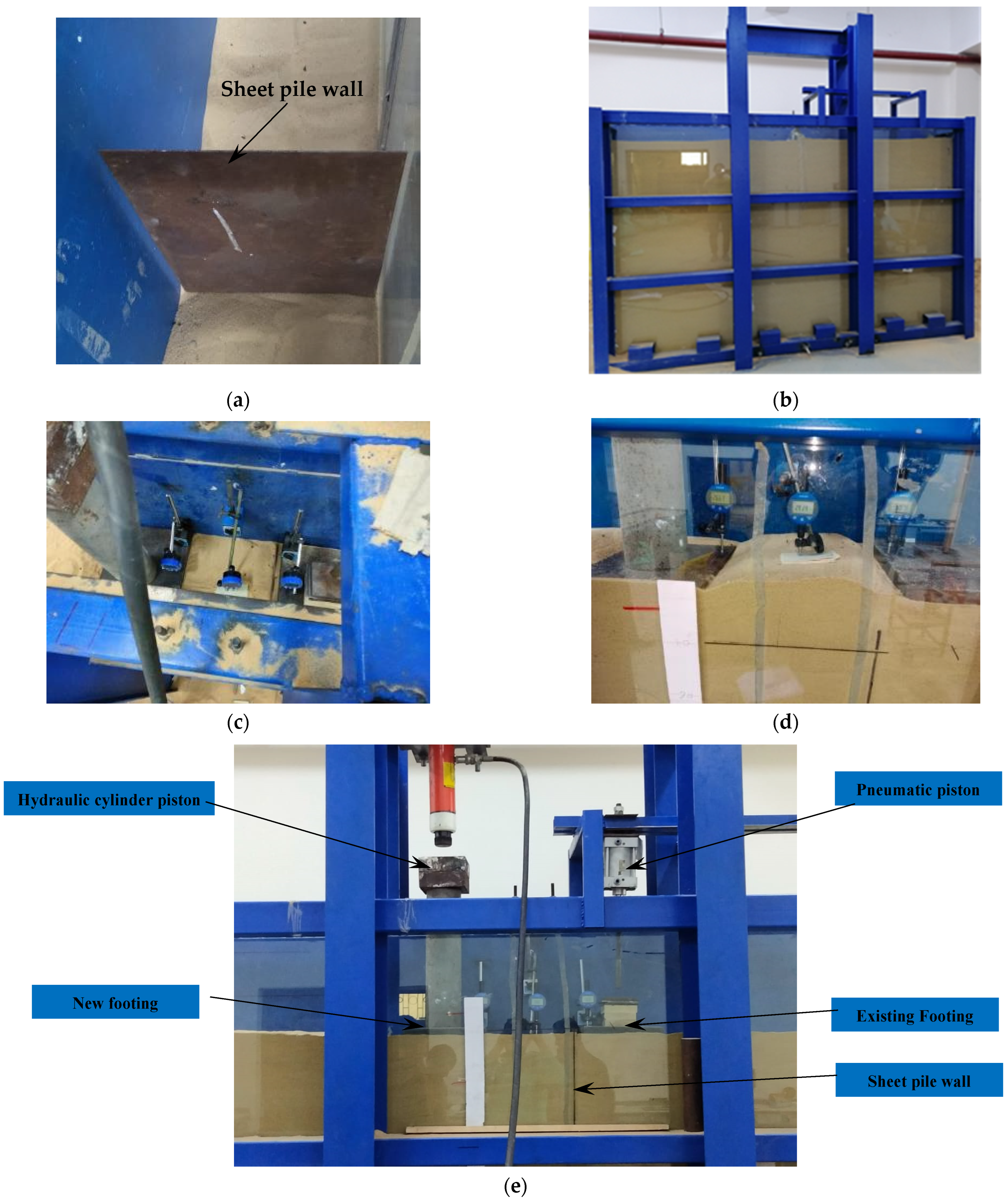
After filling the tank with sand, the tank is left for 24 h before placing the weight on the already-existing footing (F2). Next, a calibrated pneumatic piston is utilized to apply the load. The used pneumatic piston has a 100 mm bore, a 50 mm movement tolerance, and a 0.1–0.9 MPa (1.0–9.0 bar) pressure range. A medium-pressure air compressor fuels the pneumatic piston. The contact pressure (F2) beneath the footing remains constant at 100 kN/m2 during all experiments. The load on footing (F1) is applied only after the observed data have essentially stabilized (usually, there was a minimum 2 h wait). The vertical centric load is applied by using a calibrated hand-controlled loading system, which included a hydraulic cylinder piston with an axial capacity of 258 KN and a hydraulic manual pump SPX 700 bar. For three readings under the same load, the difference between two successive readings should be less than 0.01 mm every five minutes. Each increment is sustained until there was no discernible change in the footing’s deformations. The rate of increasing the load is based on Table 1. The loading system is shown in Figure 4e. After conducting a test, the sand relative density is validated by collecting samples in small metal tins with a defined volume and placing them at various positions in the soil tank before the test [33,34]. The working steps for the model testing procedure are shown in Figure 4.

3. Results and Discussion

3.1. Settlement Behavior of Single-Strip Footing

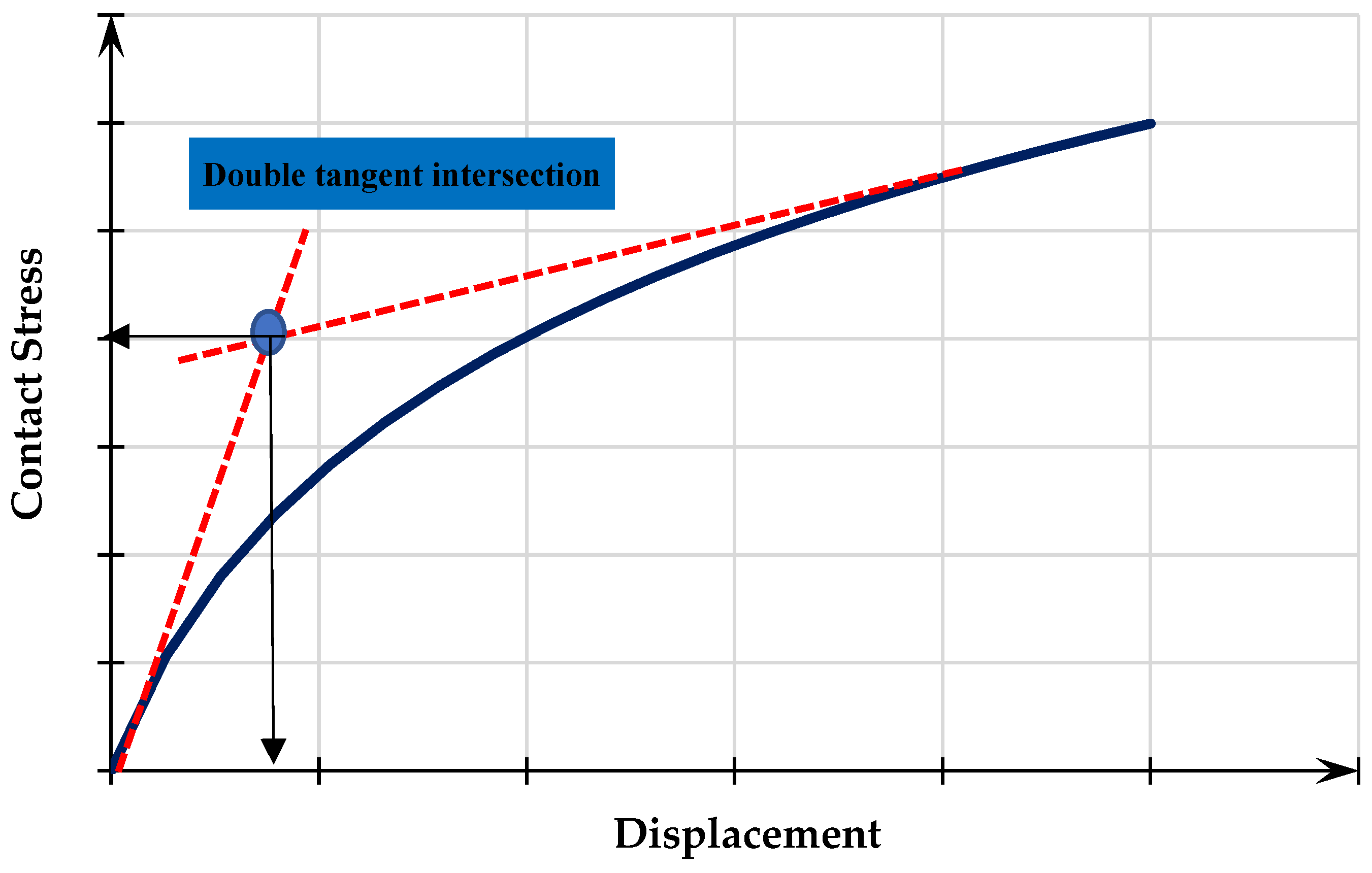
The double tangent approach, which corresponds to the intersection of tangent lines sketched between the initial flatter region and the final steeper portion of the stress–settlement curve, was used to determine the ultimate bearing capacity [35,36]. The foundation’s maximum bearing capacity, shown in Figure 5, is said to be represented by the junction of these two tangents. The stress–settlement curve of the test of a single-strip footing appears in Figure 6 and serves as a reference point (control) for comparison. Up until the bearing reached its maximum amount, the load was delivered concentrically to the single-strip footing. G0 is the single-strip footing’s test code. The ultimate bearing capacity of the single-strip footing (qult S) and the corresponding ultimate settlement (δu S) were 450 kN/m2 and 25 mm, respectively.

3.2. Settlement Behavior of Interfering New Strip Footings

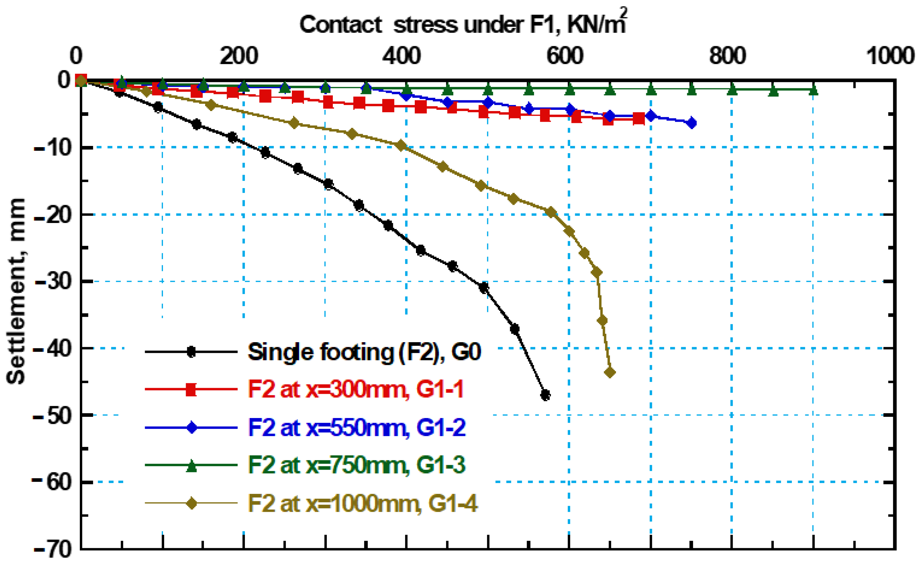
The allowable bearing capacity (qall) calculation uses a factor of safety that ranges from 2 to 3. To determine qall S, the current study employed a safety factor of 2.0. The allowed bearing capacity (1/2qall S), which remained constant throughout the test and is equivalent to 100 kN/m2, was added as a surcharge to the old strip footing. After that, the new strip footing (F1) was positioned adjacent to the previous strip footing (F2) at various distances (X = 300, 550, 750, and 1000 mm). The footing is statically loaded in 50 kN stages, per the test program, until it fails. The stress–settlement curves from four tests of the new strip footing, conducted closely apart from the previous one, are shown in Figure 6, together with one curve for the single-strip footing (G0). According to this graph, single footing has a higher settlement and less stress than other scenarios where new footing is present at various distances. Additionally, as the distance (X) between the two footings is shrunk, the applied stress increases and the settlement of the new foundation (F1) is reduced. This may stem from the presence of the new footing at a distance (X = B) from the old one causes a fixation to the new footing and the bearing capacity is increased because, as stated by Das [26], when the two foundations touch at a distance of X equal to the foundation width B, the system behaves as a single foundation with a width equal to 2B. Based on these findings, Figure 5 demonstrates that, for (F1), the largest reduction is found at (X = 300 mm) and reached 40% in comparison to single footing at stress 400 kN/m2. Also, the applied stress is increased with decreasing distance between footings—it is increased by 53% at a distance (X = 300) mm compared to single footing.

3.3. Settlement Behavior of Existing Strip Footing with Changing the Center-to-Center Distance Between the New and Old Footings

According to experimental research, installing new footings appears to have an impact on the way the existing ones behave. When the new footing is built at a proximity (X) to the old footing, the old footing settles more. In the scenario where X = B, the old footing settlement increases the most. Furthermore, as can be seen from the experimental results, the settlement is decreased as the distance X between the two footings is increased. For example, when the distance X is increased to 1000 mm, the settlement of the old footing is decreased, and each footing behaves as if it were a separate footing with no influence from the other. The settlement behavior of an ancient foundation is presented in Figure 7 as the X-distance between the two footings is increased. This figure shows that in comparison to the situation of a single footing, the old footing settlement has increased with a high ratio reaching 96% and 89% at X = 300 mm and 550 mm, respectively. While the settlement is enhanced with a slight ratio that reaches 47% when X = 1000 mm is used.
In comparison to previous studies that utilized centrifuge testing to evaluate the interaction between foundations and tunneling-induced ground displacements, several similarities and some important differences are observed. Specifically, Xu et al. [37] conducted centrifuge tests on soil–structure interaction for various foundation types, including raft and separate footings, under tunneling-induced loading. Their findings highlighted a significant impact of foundation type on both vertical and horizontal displacements, as well as shear strains. Similar to these observations, the tests conducted in the present study indicate that footing pressure and displacement behavior exhibit clear dependence on both the foundation configuration and the soil density (dense versus loose sands). However, while Xu et al. reported a more pronounced settlement in separate footings compared to raft foundations, the results from this study show relatively smaller differential settlements, possibly due to variations in experimental setup and boundary conditions. These differences underscore the importance of considering site-specific parameters, such as soil type and boundary constraints, when interpreting footing load testing results under tunneling effects.

3.4. Settlement Behavior of Interfering New Strip Footings with SPW

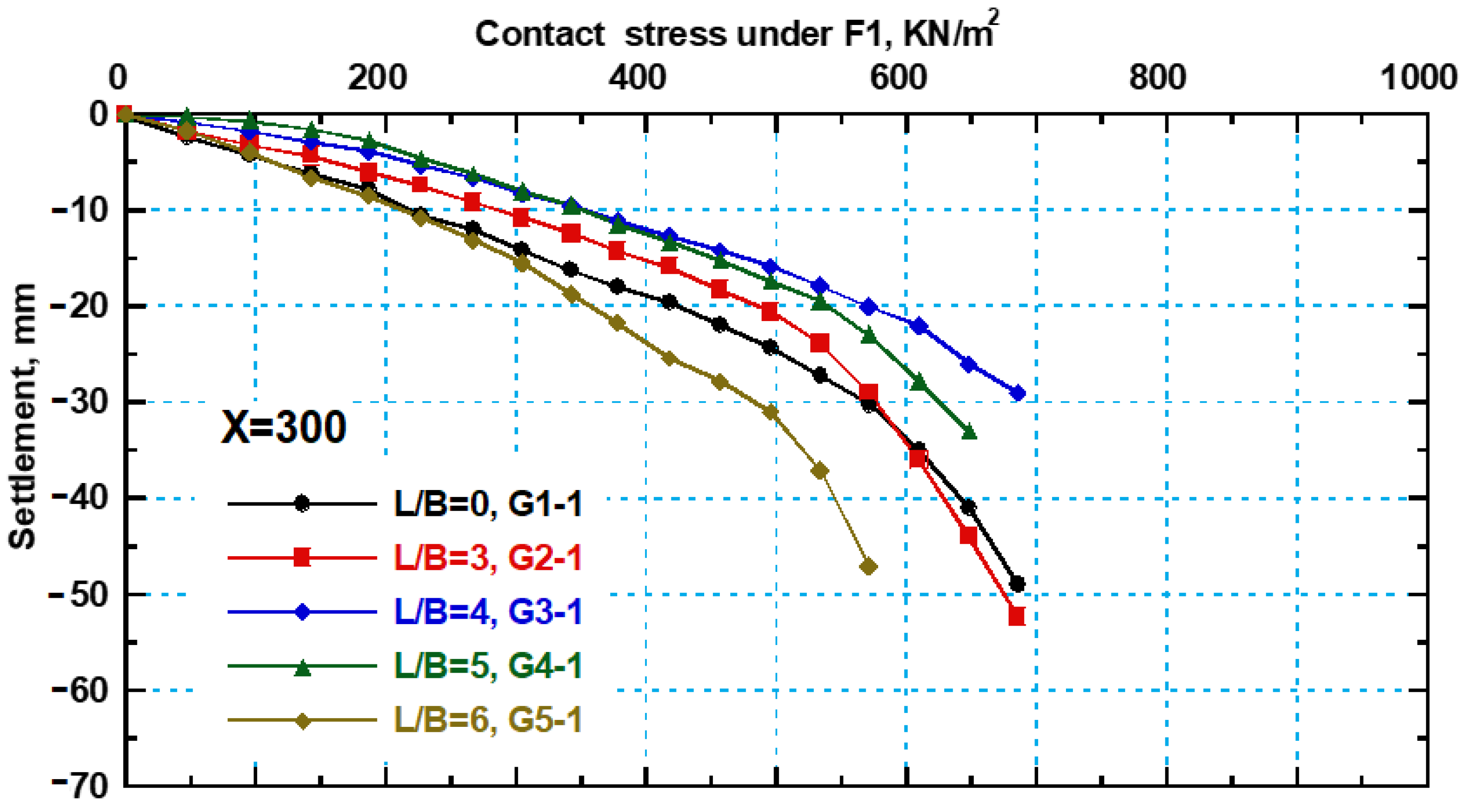
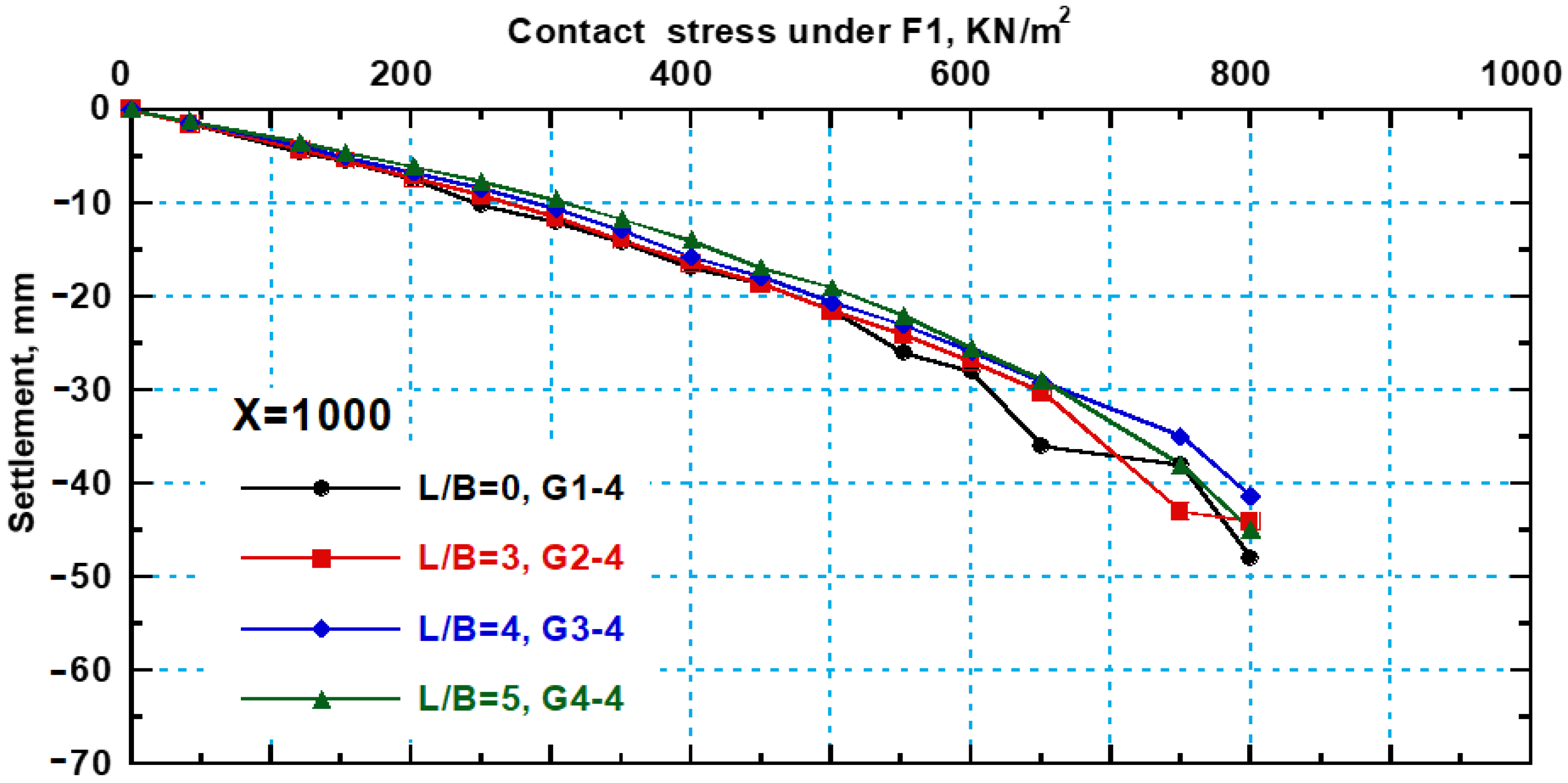
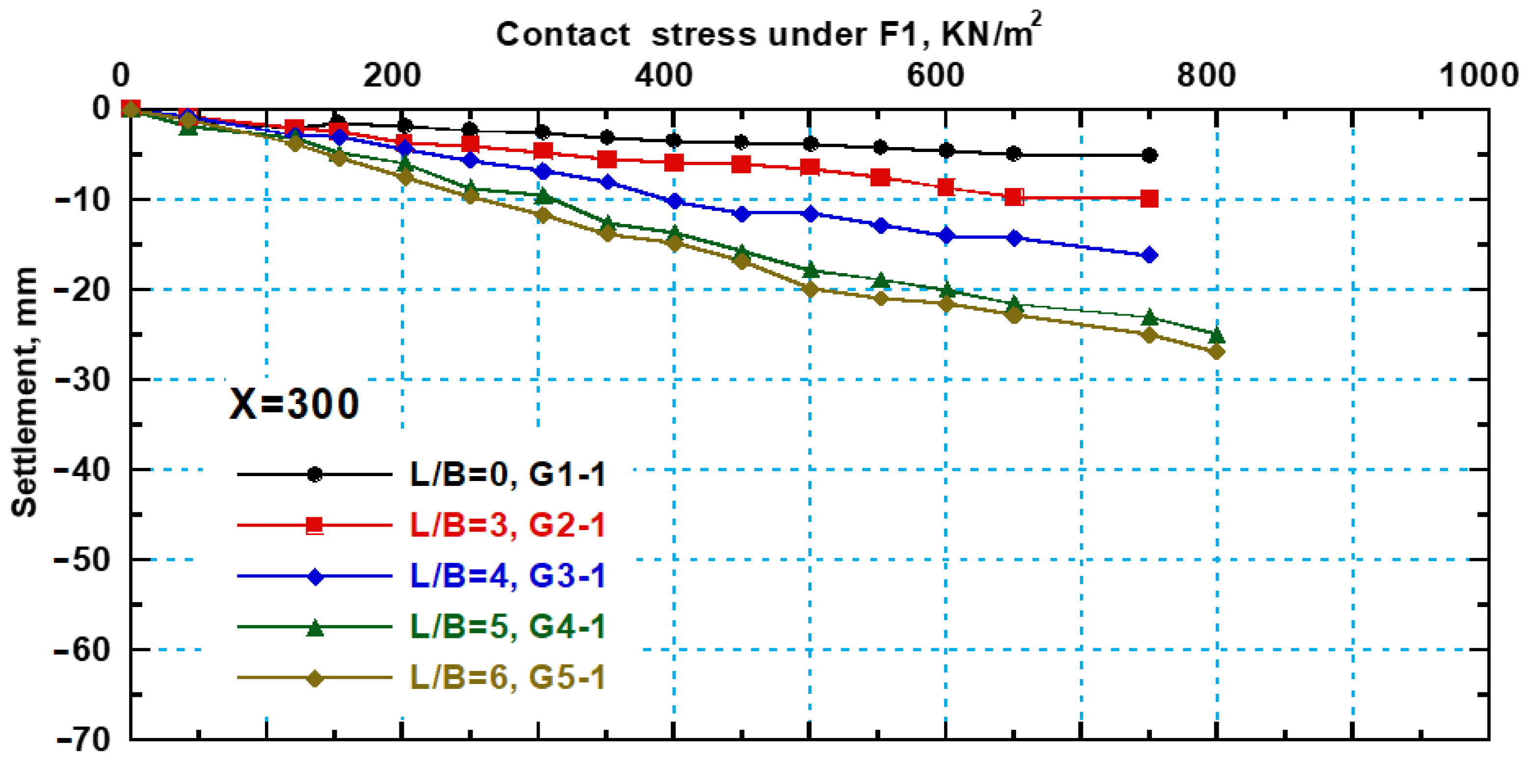
For various Ls/B ratios, where L is the length of the sheet pile wall (SPW) and B is the footing width, the variation in the stress–settlement curves of the new strip footing (F1) are explored. This footing is situated at a proximity (X = 300 mm) to the current footing (F2). As can be observed from Figure 8, the applied stress rose as the length of the sheet pile wall grew for the new footing (F1). When Ls/B is 3, 4, and 5, it rises by 15% and 25%, respectively. When Ls/B is 6, a 40% rise over an Ls/B of zero is observed, which is the highest increase ever. Also, the settlement of the new footing (F1) is found to be decreased with increasing length of the sheet pile wall. As illustrated in Figure 8 the settlement is decreased with a ratio reaching 23% at an Ls/B of 3 using the SPW compared to an Ls/B of zero. Then, the settlement is found to be decreased gradually with increasing Ls/B ratio—it is decreased by 36%, 45% and 48% when Ls/B is 4, 5, and 6, respectively, compared to the footing without sheet piles (Ls/B = 0). Moreover, the settlement behavior of the new strip footing (F1) is studied also when it is located at a larger distance (X) of 1000 mm from the existing old footing (F2) with increasing Ls/B ratio. From the results, it is noticed that the settlement of the new footing (F1) is decreased with increasing Ls/B ratio. It is decreased by 13% at an Ls/B ratio of 3 and 20% at an Ls/B ratio of 4 and 5, respectively, at a constant stress of 600 kN/m2 compared to an Ls/B of zero as presented in Figure 9. Also, the applied stress is found to be increased with increasing sheet pile length, the maximum increase in stress reached 25% when Ls/B is 5. Finally, by comparing the stress–settlement behavior of the new footing (F1), which is located at different distances (X = 300 mm and 1000 mm) from the old footing (F2), it is found that increasing the distance between the new and old footing the settlement decreased and the applied stress increased. It is found that when the Ls/B ratio is 5, the settlement of footing (F1) is decreased by 45% and 25% at X = 300 mm and 1000 mm, respectively, due to lateral confinement effect as stated by Azzam [38]. This confirmed that when the distance between the two footings is small and equal to the width of one footing (B), the settlement behavior improved and decreased gradually with increasing SPW length. This is due to the behavior of the two footings which act as one footing with a width equal to 2B due to the bonding between the two footings which resulted from the touch between them at a small distance X = B.

3.5. Settlement Behavior of Existing Strip Footing with Different SPW Lengths

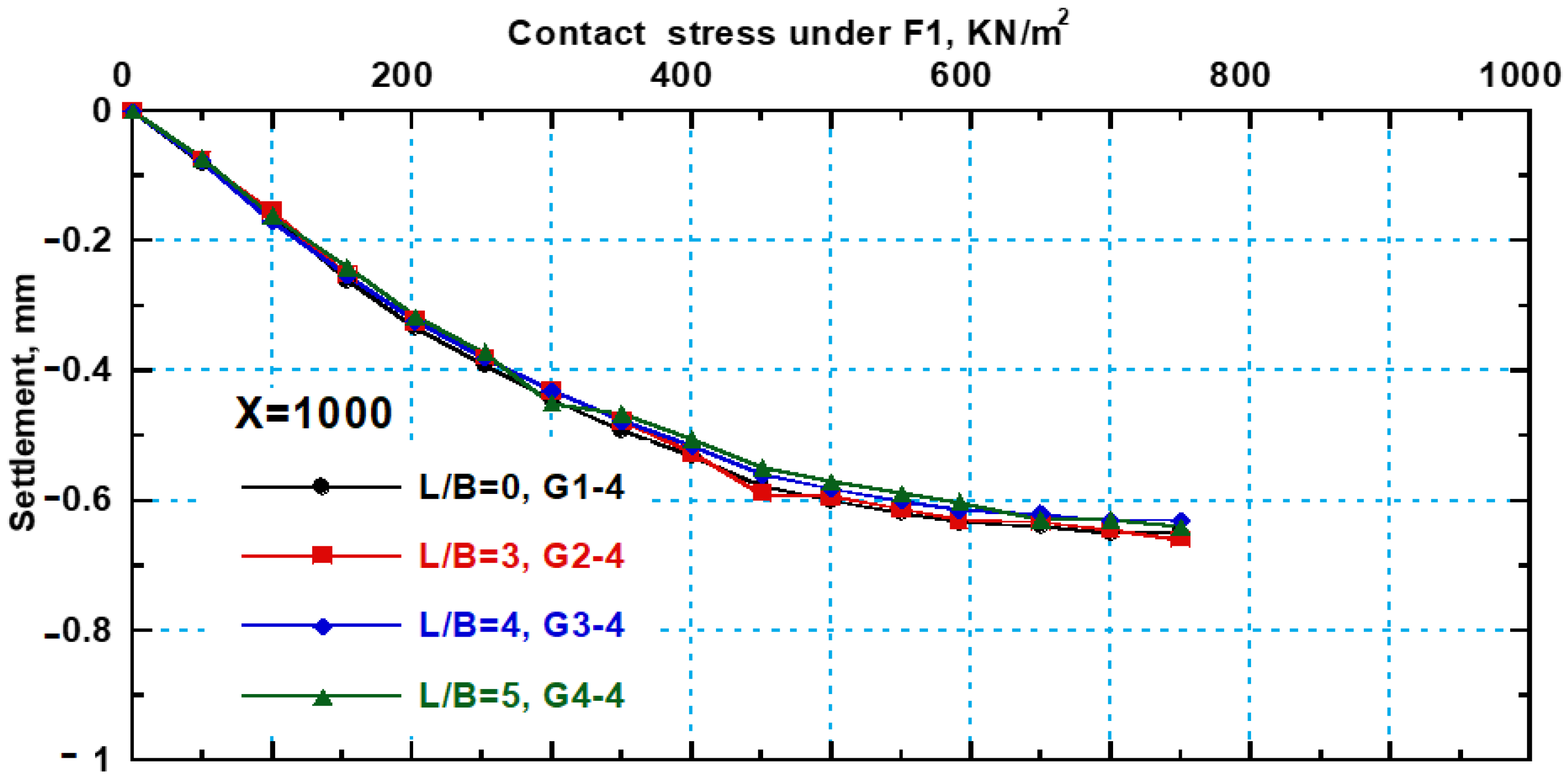
In this section of this study, the stress–settlement behavior of an existing strip footing with a modified sheet pile wall length is examined. The installation of a new strip footing (F1) at proximity (X = B) has a negative impact on the behavior of the old strip footing (F2) in terms of settlement; nevertheless, the settlement of the new footing (F1) in this scenario is improved and decreased with a high ratio. On the other hand, it is discovered that as the distance X between the two footings increases, the settling of the old footing (F2) improves because, at large distance X, the installation of the new footing (F1) becomes ineffective on the old footing (F2). Sheet pile walls are used to improve the settling behavior of an existing strip footing (F2) when a new strip footing (F1) is constructed next to it at close quarters. The stress–settlement behavior for the old footing (F2) is examined at various sheet pile lengths using various sheet pile lengths. The stress–settlement curves of an old strip footing (F2) are shown in Figure 10 and Figure 11 for various sheet pile lengths and separations of X = 300 mm and 1000 mm. The settlement of the old footing (F2) is first shown to grow at a minor distance of X = 300 mm and contact stress of 500 kN/m2, with a high ratio reaching 85% at Ls/B = 0 compared to the settlement of the old footing without the presence of the new footing. Additionally, it is discovered that the settlement of the old footing (F2) is reduced when a sheet pile wall is used. The reduction ratio of footing settlement gradually increased with increasing sheet pile length, and at an optimum value of sheet pile length (Ls/B = 5), the settlement reduction in the old footing (F2) becomes nearly constant. As presented in Figure 10, the settlement of the old footing (F2) is decreased by 47% 67% and 77% at Ls/B = 3, 4, and 5, respectively, and the stress is 500 kN/m2 compared to the settlement at Ls/B = 0. Also, from the same figure the contact stress is found to be increased with increasing sheet pile length. The applied stress is increased by 10%, 15%, and 20% at Ls/B = 3, 4, and 5, respectively, compared to an Ls/B = 0. On the other hand, the stress–settlement behavior of the old strip footing (F2) is studied in the installation of new footing at a large distance X = 1000 mm. Figure 11 illustrates the stress–settlement behavior of the old footing at different Ls/B ratios. It is noticed from this figure that the settlement behavior is almost the same settlement of the existing footing without the installation of the new one due to the lack of effect for the new footing installation at a large distance X. The settlement is found to be decreased with increasing sheet pile length—it is reduced by 5%, 5.5% and 6% at Ls/B = 3, 4 and 5, respectively, compared to when Ls/B = 0.
Franza et al. [39] focused on the effectiveness of pile walls in reducing tunneling-induced displacements, finding that they significantly mitigate vertical movements near the tunnel but are less effective for horizontal displacements, especially when placed further from the tunnel. The current study aligns with these findings by confirming that pile walls reduce vertical displacements, but it extends the analysis by considering multiple types of parameters and varying soil conditions.

3.6. Effect of Changing the Center-to-Center Distance Between the Two Footings on the Bearing Capacity Factor of Strip Footing

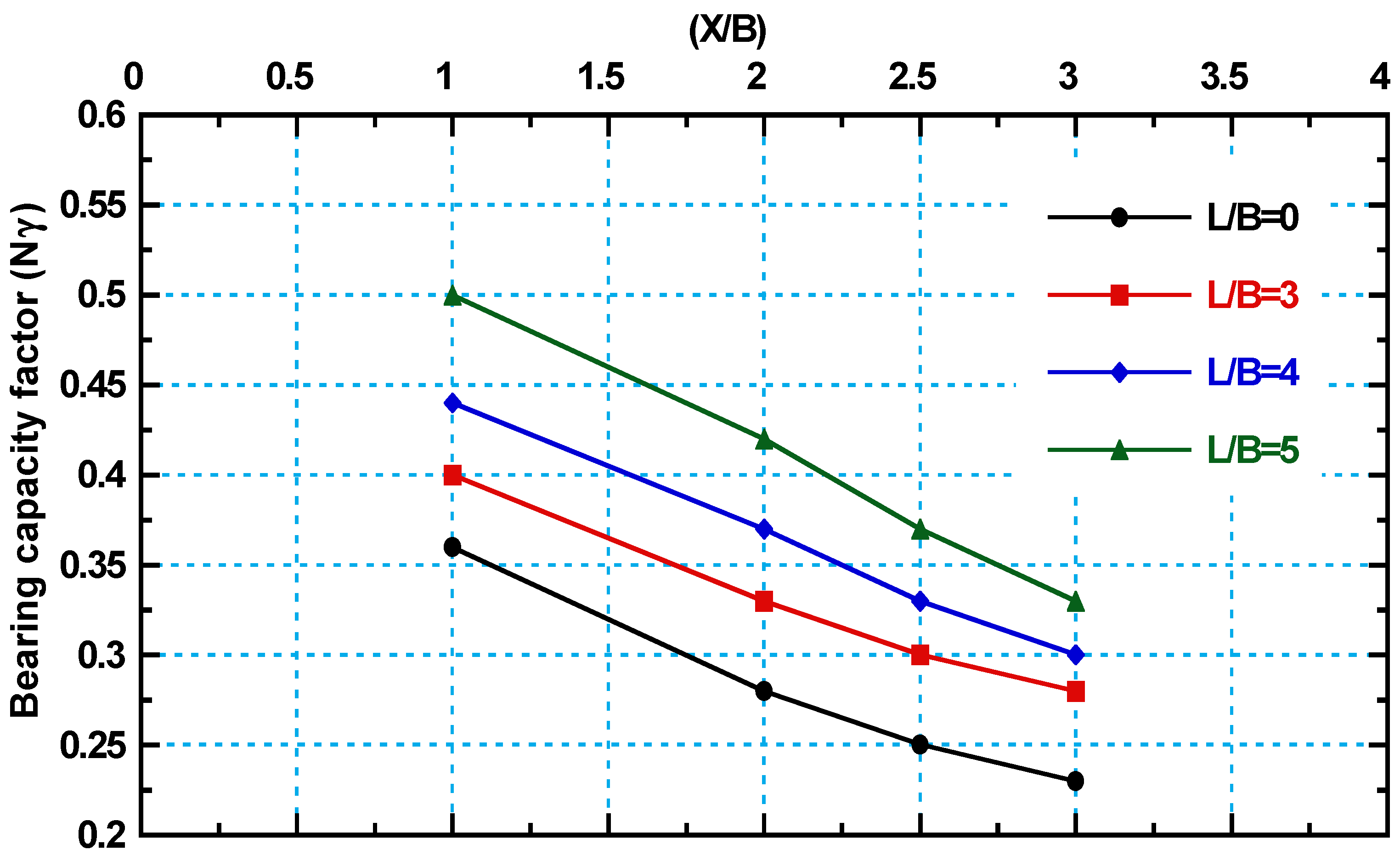
This section of this study presents how the center-to-center distance affects the bearing capacity factor (N). As previously noted, the old strip footing (F2)’s bearing capacity reduces with a reduction in X due to the installation of the new footing, but the new strip footing’s bearing capacity improves with a reduction in X. Additionally, it could be because, at X/B = 1 and 1.5, two closely separated strip footings behave as one footing. This is owing to when X/B is small, the soil between the two footings creates an inverted arch that descends with the foundation as a unit when the load is applied. The zone or arching vanishes when X/B = l, and the system then operates as a single foundation with width 2B. Equation (3) is used to calculate the bearing capacity factor (Nγ) at various qult values for X = 300 mm, 500 mm, 750 mm, and 1000 mm. In Figure 12, the bearing capacity factor and distance X are explored and exhibited in connection to one another. This figure makes it evident that for the new strip footing (F1), the bearing capacity factor increases with reducing the distance X at various Ls/B ratios. In comparison to (Nγ) at X/B = 0 at Ls/B ratio = 0, the bearing capacity factor (Nγ) is raised by 60%, 75%, and 80% at X/B = 1, 2, and 3, accordingly. On the other hand, it has been discovered that as SPW length increases, the bearing capacity factor also increases. As demonstrated in Figure 12, the bearing capacity factor (Nγ) increases by 15%, 30%, and 43% at Ls/B = 3, 4, and 5 compared to (Nγ) at Ls/B = 0 at a constant (X/B) ratio of 1. Additionally, it is discovered that the bearing capacity factor (Nγ) at Ls/B= 0 increases by 20%, 35%, and 55% at Ls/B = 3, 4, and 5, accordingly, at (X/B) ratios of 2.
q u l t = 1 2 γ B N γ
The study by Xu et al. [40] further validates the findings by numerically investigating the influence of embedded wall length and the horizontal distance from the tunnel on the displacement of the surrounding soil. Their research demonstrated that increasing the embedded wall length and adjusting the distance from the tunnel significantly mitigated ground movement, particularly in reducing horizontal displacements and soil settlement near the tunnel. Similarly, the results from this study indicate a reduction in both vertical and horizontal displacements as the protective wall’s depth and distance from the tunnel were increased. However, it was observed that the displacement reduction rate began to plateau after a certain threshold of wall depth, which concurs with the findings of Xu et al. [40]. This suggests that while embedded walls effectively protect nearby structures, there is an optimal depth and distance beyond which the benefits in reducing ground movements become marginal. These observations reinforce the need for an empirical design approach, considering both the wall length and its placement relative to tunnel depth.
Building on the work of Song et al. [41], who examined the effects of protective wall depth on structural deformations caused by tunneling, similar trends in terms of the wall’s ability to reduce tunneling-induced damage were observed in this study. In their study, the optimal wall depth was determined to be approximately 1.25 times the tunnel axis depth, with minimal additional benefits observed beyond this depth. The analysis in this study confirmed that increasing the protective wall’s depth improves the reduction in structural distortions, but the benefits become less pronounced as the depth surpasses this threshold. This observation underscores the importance of optimizing the wall depth during the design phase to avoid unnecessary cost and material usage while still achieving effective protection against tunneling-induced soil movements. Furthermore, the redistribution of loads and the subsequent effects on pile settlements observed in this study are in agreement with the results reported by Song et al. [41], who noted that wall depth plays a crucial role in load distribution and mitigating structural damage.

3.7. The Failure Mechanism from Experimental Results Under Two Adjacent Foundations at Different Values for the Distance X Between the Two Footings

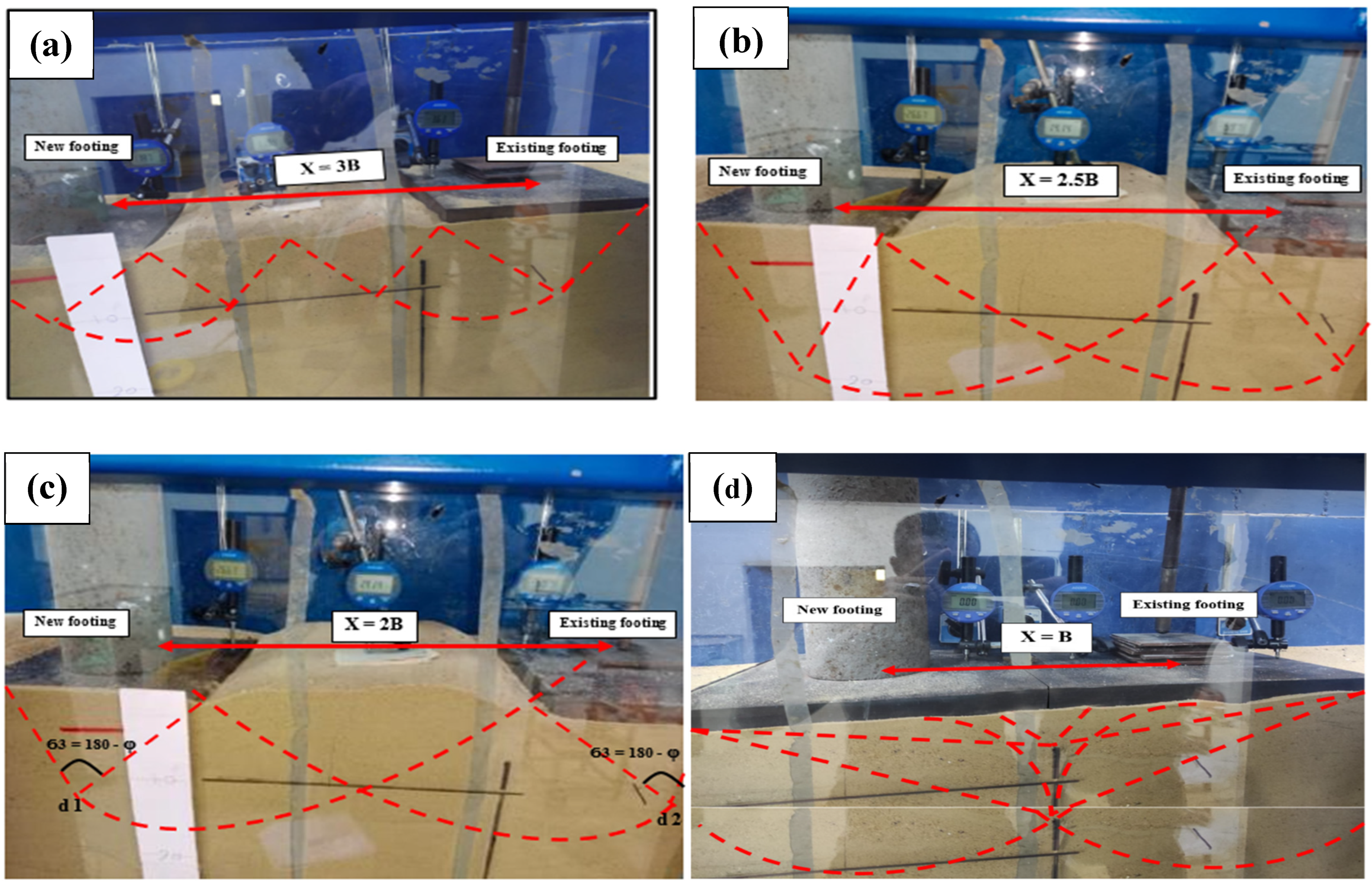
According to experimental studies, when two footings are placed close to one another with comparable soil conditions, the ultimate bearing capacity of the new and old footings may be reduced because of the interference effect of the failure surface in the soil. Stuart’s [3] findings support this conclusion. Building on experimental failure modes, the rupture surface in the soil beneath two footings does not overlap as illustrated in Figure 13a if the center-to-center spacing of the two-strip footing (X) is equal to 3B, where B is the footing width. On the other hand, it can be observed from the failure pattern that the Rankine passive zones simply overlap when the center-to-center distance (X) between the new and old footings is equal to 2.5B, as shown in Figure 13b. Additionally, it can be shown in Figure 13c that the triangle wedges in the soil under the foundation make 180° − 2ϕ angles at sites E1 and E2 where the center-to-center spacing between the two adjacent strip footings (X) is 2B. The zone of arching vanishes when the two foundations come into contact, and the system then functions as a single foundation with width 2B. Blocking will take place, and the two foundations will function as a single foundation, as shown in Figure 13d.

4. Practical Implementation Based on Research Findings

The findings of this study provide essential insights for the practical design of strip footings and their interactions with neighboring footings. Based on the results, it is clear that the spacing between strip footings plays a crucial role in the overall behavior of the foundation system, especially in terms of settlement and bearing capacity. In practical terms, this means that engineers should carefully evaluate the spacing between strip footings to ensure that the load distribution remains efficient while minimizing excessive settlement. For example, if the soil conditions are dense or prone to settlement, reducing the spacing between adjacent footings can prevent overloading and ensure that the foundation maintains its stability and durability over time.
Another key takeaway from this study is the beneficial effect of sheet pile walls in enhancing the bearing capacity of foundations. The research found that when sheet pile walls are incorporated around strip footings, they help to control lateral displacement and reduce the risk of settlement. This practical application is particularly relevant in areas with weak or unstable soil. In such cases, incorporating sheet pile walls can provide significant improvements in foundation performance by providing additional lateral support and increasing the overall bearing capacity. Engineers working on foundations in such conditions can apply this solution to mitigate settlement issues and enhance the stability of the foundation without the need for more complex or costly deep foundation methods.
This study also highlights that the interaction between strip footings must be considered, especially when they are in close proximity to one another. The proximity affects how the load is distributed and can influence the settlement behavior. In practice, engineers can use this information to design foundations that optimize the spacing between footings, ensuring that adjacent footings do not negatively affect one another. By adjusting the spacing according to the findings, it is possible to minimize settlement and achieve a more uniform and stable foundation system. This is particularly important for large-scale construction where multiple footings are used in a single foundation layout.
In summary, the practical implementation of these findings involves optimizing footing spacing, using sheet pile walls for increased stability, and ensuring that proper soil analysis is conducted before design. Engineers can take advantage of these insights to create cost-effective, reliable, and durable foundations for buildings, improving safety, reducing settlement risks, and enhancing long-term stability.

5. Conclusions

This study aims to investigate the effect of center-to-center spacing (X) between adjacent strip footings and sheet pile wall (SPW) penetration depth (Ls/B) on foundation performance in sandy soil. The research focuses on how SPWs influence settlement behavior and bearing resistance under vertical loads. A series of laboratory experiments were conducted using a large-scale soil tank, with X varying from 300 mm to 1000 mm and SPW lengths ranging from 0 mm to 1500 mm. The following conclusions can be drawn:
  • The new footing (F1) settlement decreases, and the applied stress increases as the distance (X) between footings decreases. At X = B, the new and old footings act as a single foundation with a width of 2B, enhancing fixation and increasing bearing capacity due to improved load distribution and reduced differential settlement.
  • The maximum reduction for the settlement of (F1) is found at (X = 300 mm) and reached 40% compared with single footing at stress = 400 kN/m2.
  • Also, the applied stress at (F1) is found to be increased with decreasing distance between footings—it is increased by 53% at distance (X = 300 mm) compared with single footing.
  • The settlement of the old footing is increased when decreasing the distance X and the maximum increase in the old footing settlement is found at X = B.
  • The settlement of the old footing is increased with a high ratio reached 96% and 89% at X = 300 mm and 550 mm, while, when using distance X = 1000 mm, the settlement is increased with a small ratio reached 47% compared to single footing.
  • The new footing (F1) settlement decreased with a ratio reaching 23% when Ls/B is 3. Then, the settlement is found to decrease gradually with increasing Ls/B ratio; it decreases by 36%, 45%, and 48% when Ls/B is 4, 5, and 6, respectively, compared to the footing without sheet piles (Ls/B = 0).
  • While the settlement of the old footing (F2) is found to be decreased when using SPW, the reduction ratio of settlement is increased gradually with increasing sheet pile length until sheet pile length (Ls/B) = 5, the settlement reduction in (F2) becomes almost constant.
  • The settlement of the old footing (F2) decreases by 47%, 67%, and 77% at Ls/B = 3, 4, and 5, respectively, and the stress is 500 kN/m2 compared to the settlement at Ls/B = 0.
  • This study highlights the effectiveness of SPWs in improving foundation behavior, reducing settlement, and enhancing bearing capacity, especially in densely built environments with limited foundation spacing. The results suggest that an SPW length-to-footing width ratio (Ls/B) between 4 and 5 is optimal for minimizing settlement and improving stability, with only a slight difference in effectiveness between these two ratios.

Author Contributions

Conceptualization, A.M.B. and M.H.Z.; data curation, A.M.B. and M.H.Z.; formal analysis, A.M.B. and M.H.Z.; investigation, A.M.B. and M.H.Z.; methodology, A.M.B. and M.H.Z.; visualization, A.M.B. and M.H.Z.; writing—original draft, A.M.B. and M.H.Z.; writing—review and editing, A.M.B., M.H.Z. and A.Y.A. All authors have read and agreed to the published version of the manuscript.

Funding

This research received no external funding.

Institutional Review Board Statement

Not applicable.

Informed Consent Statement

Not applicable.

Data Availability Statement

All referenced data are contained within this paper.

Conflicts of Interest

The author declares no conflicts of interest.

References

  1. Chenari, R.; Mohafezatkar, A. Adjacent building induced settlement reduction in residential constructions. Forensic Approach Anal. Geohazard Probl. 2010, 169. [Google Scholar] [CrossRef]
  2. Eltohamy, A.; Zidan, A. Performance of interfering strip footings resting on reinforced sand under uniform and non-uniform load-experimental and numerical study. J. Am. Sci. 2013, 9, 421–430. [Google Scholar]
  3. Stuart, J.G. Interference between foundations, with special reference to surface footings in sand. Geotechnique 1962, 12, 15–22. [Google Scholar]
  4. Eslami, A.; Afshar, D.; Moghadasi, H.; Akbarimehr, D. Numerical and experimental investigations of interference effect of adjacent buildings on sand and fill deposits. Int. J. Civ. Eng. 2023, 22, 723–738. [Google Scholar] [CrossRef]
  5. Ghosh, P.; Sharma, A. Interference effect of two nearby strip footings on layered soil: Theory of elasticity approach. Acta Geotech. 2010, 5, 189–198. [Google Scholar]
  6. Selvadurai, A.P.S.; Rabbaa, S.A.A. Some experimental studies concerning the contact stresses beneath interfering rigid strip foundations resting on a granular stratum. Can. Geotech. J. 1983, 20, 406–415. [Google Scholar]
  7. Das, B.M.; Larbi-Cherif, S. Bearing capacity of two closely-spaced shallow foundations on sand. Soils. Found. 1983, 23, 1–7. [Google Scholar]
  8. Hanna, A.M. Bearing capacity of foundations on a weak sand layer overlying a strong deposit. Can. Geotech. J. 1983, 19, 392–396. [Google Scholar]
  9. Basha, A.; Zakaria, M.; El-Nimr, M.; Abo-Raya, M. Performance analysis of axially loaded secant pile wall embedded in sand: An experimental investigation. Arab. J. Sci. Eng. 2023, 48, 13005–13029. [Google Scholar]
  10. Basha, A.M.; Zakaria, M.H.; El-Nimr, M.T.; Abo-Raya, M.M. Predicting the maximum axial capacity of secant pile walls embedded in sandy soil. Geotech. Geol. Eng. 2024, 24, 3373–3400. [Google Scholar]
  11. Ozpolat, A.; Aksoy, H.S. The effect of distance between sheet pile and foundation on bearing capacity of Foundation. Adv. Civ. Eng. 2022, 2022, 7338718. [Google Scholar] [CrossRef]
  12. Jayamohan, J.; Vimal, A.; Rajeev, K.P. Behaviour of strip footing resting on reinforced foundation bed with underground void. Indian J. Geosynth. Ground Improv. 2022, 9, 25–29. [Google Scholar]
  13. Basha, A.; Elsiragy, M. Effect of sheet pile driving on geotechnical behavior of adjacent building in sand: Numerical study. Civ. Eng. J. 2019, 5, 1726–1737. [Google Scholar]
  14. Salamatpoor, S.; Jafarian, Y.; Hajiannia, A. Bearing capacity and uneven settlement of consecutively constructed adjacent footings rested on saturated sand using model tests. Int. J. Civ. Eng. 2019, 17, 737–749. [Google Scholar]
  15. Alwalan, M.F. Interaction of closely spaced shallow foundations on sands and clays: A review. J. Adv. Eng. Res. Sci. 2018, 5, 101–110. [Google Scholar]
  16. Denver, H.; Kellezi, L. Modelling of earth pressure from nearby strip footings on a free & anchored sheet pile wall. In Proceedings of the 17th Nordic Geotechical Meeting Challenges in Nordic Geotechniqes, Reykjavik, Iceland, 25–28 March 2016; pp. 913–921. [Google Scholar]
  17. Debnath, A.; Pal, S. Influence of surcharge strip loads on the behavior of cantilever sheet pile walls: A numerical study. J. Eng. Res. 2023, 11, 100029. [Google Scholar]
  18. Singh, A.; Chatterjee, K. Influence of soil type on static response of cantilever sheet pile walls under surcharge loading: A numerical study. Arab. J. Geosci. 2020, 13, 138. [Google Scholar]
  19. Kumar, J.; Ghosh, P. Ultimate bearing capacity of two interfering rough strip footings. Int. J. Geomech. 2007, 7, 53–62. [Google Scholar] [CrossRef]
  20. Pusadkar, S.; Bhatkar, T. Behaviour of raft foundation with inclined skirt using PLAXIS 2D. In Proceedings of theIndian Geotechnical Conference, Roorkee, India, 22–24 December 2013; Volume 3. [Google Scholar]
  21. Mowafe, Y.; Eltohamy, A.; Mohamed, A. Performance of cantilever sheet pile supporting excavation adjacent to strip footing. In Proceedings of the 2nd International Conference on Geotechnique, Construction Materials and Environment, Kuala Lumpur, Malaysia, 14–16 November 2012. [Google Scholar]
  22. Kumar, J.; Bhoi, M.K. Interference of two closely spaced strip footings on sand using model tests. J. Geotech. Geoenvironmental Eng. 2009, 135, 595–604. [Google Scholar]
  23. Das, B.M.; Puri, V.K.; Neo, B.K. Interference effects between two surface footings on layered soil. Transp. Res. Rec. 1993, 34–40. Available online: https://trid.trb.org/View/384534 (accessed on 1 January 2025).
  24. Stuart, J.; Hanna, T. Groups of deep foundations, a theoretical and experimental investigation. In Proceedings of the 5th International Conference on Soil Mechanics and Foundation Engineering, Paris, France, 17–22 July 1961; pp. 149–153. [Google Scholar]
  25. Terzaghi, K. Theoretical Soil Mechanics; Wiley: New York, NY, USA, 1943. [Google Scholar] [CrossRef]
  26. Das, B. Shallow Foundations: Bearing Capacity and Settlement; CRC Press: Boca Raton, FL, USA, 2017. [Google Scholar]
  27. Xu, J.; Zheng, L.; Yu, Z.; Li, Y.; Cai, G. Effects of bending stiffness and interface roughness on tunnel-embedded wall interaction. Tunn. Undergr. Space Technol. 2025, 155, 106209. [Google Scholar]
  28. ASTM. Standard Test Method for Particle-Size Analysis of Soils (ASTM D422-63); ASTM International: West Conshohocken, PA, USA, 2007. [Google Scholar]
  29. ASTM, D. 3–9; Standard Test Method for Direct Shear Test of Soils under Consolidated Drained Conditions. ASTM International: West Conshohocken, PA, USA, 2011.
  30. Aamer, F.; Azzam, W.; Farouk, A.; Nasr, A.; Nazir, A. Utilization of blade anchor for improving the uplift capacity of pile in sand: Model study. Ocean Eng. 2023, 278, 114435. [Google Scholar] [CrossRef]
  31. Azzam, W.; Elwakil, A. Model study on the performance of single-finned pile in sand under tension loads. Int. J. Geomech. 2017, 17, 4016072. [Google Scholar] [CrossRef]
  32. Nasr, A.M.A.; Azzam, W.R. Behaviour of eccentrically loaded strip footings resting on sand. Int. J. Phys. Model. Geotech. 2017, 17, 177–194. [Google Scholar] [CrossRef]
  33. El Sawwaf, M.; Nazir, A. Behavior of eccentrically loaded small-scale ring footings resting on reinforced layered soil. J. Geotech. Geoenvironmental Eng. 2012, 138, 376–384. [Google Scholar] [CrossRef]
  34. Vinod, P.; Bhaskar, A.; Sreehari, S. Behaviour of a square model footing on loose sand reinforced with braided coir rope. Geotext. Geomembr. 2009, 27, 464–474. [Google Scholar] [CrossRef]
  35. Hataf, N.; Fatolahzadeh, A. An experimental and numerical study on the bearing capacity of circular and ring footings on rehabilitated sand slopes with geogrid. J. Rehabil. Civ. Eng. 2019, 7, 174–185. [Google Scholar]
  36. Mansur, C.; Kaufman, R. Pile tests, low-sill structures, old river, La. J. Soil Mech. Found. Div. 1956, 82, 1071–1079. [Google Scholar] [CrossRef]
  37. Xu, J.; Franza, A.; Marshall, A.M.; Losacco, N.; Boldini, D. Tunnel–framed building interaction: Comparison between raft and separate footing foundations. Géotechnique 2021, 71, 631–644. [Google Scholar] [CrossRef]
  38. Azzam, W. Utilization of confined cell for improving the machine foundation behavious. J. GeoEng. 2017, 10, 17–23. [Google Scholar]
  39. Franza, A.; Losacco, N.; Ledesma, A.; Viggiani, G.M.; Jimenez, R. Protecting surface and buried structures from tunnelling using pile walls: A prediction model. Can. Geotech. J. 2021, 58, 1590–1602. [Google Scholar] [CrossRef]
  40. Xu, J.; Zheng, L.; Song, G.; Zhang, D.; Sheil, B.; Marshall, A.M. Effects of embedded walls on tunnelling-induced sandy ground displacements: A numerical investigation. Géotechnique 2024, 21, 1–14. [Google Scholar]
  41. Song, G.; Xu, J.; Marshall, A.M. Numerical study on the effect of protective wall depth in reducing structure deformations caused by tunnelling. Comput. Geotech. 2023, 158, 105374. [Google Scholar]
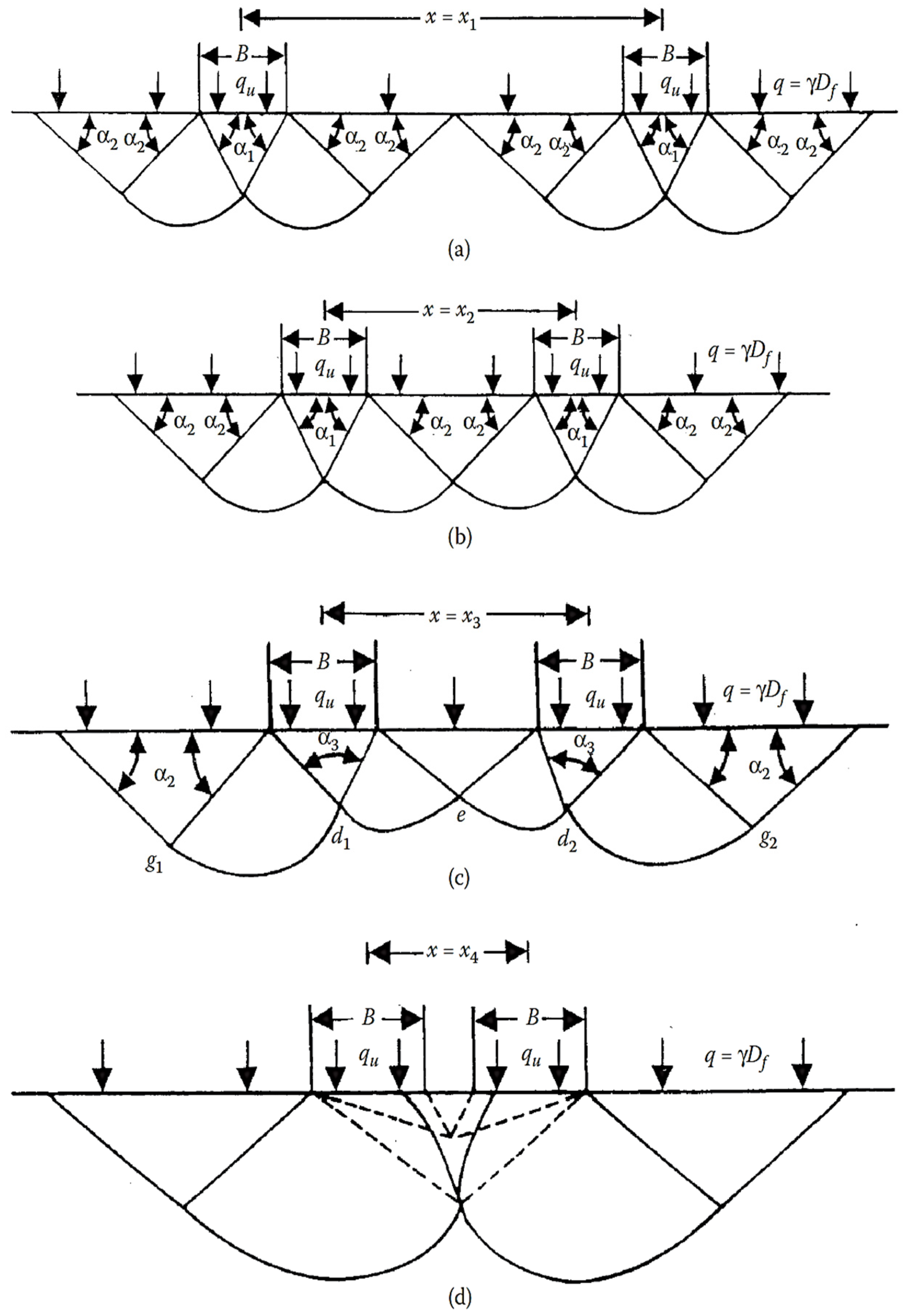
Figure 1. Assumption for the failure surface of cohesionless soil under two adjacent foundations (a) x = x1; (b) x = x2; x = x3; (c) x = x3; (d) x = x4 (adopted and modified from Das [26]). Note: α1 = ϕ, α2 = 45 − ϕ/2, α3 = 180 – ϕ.
Infrastructures 10 00083 g001
Figure 2. Schematic elevation view: (a) test setup and, (b) variable parameters used in the experimental study.
Infrastructures 10 00083 g002
Figure 3. Details and dimensions of soil tank.
Infrastructures 10 00083 g003
Figure 4. Testing procedure: (a) placement of sand around sheet pile, (b) testing tank filled with sand soil during the test, (c) during loading, (d) at failure, and (e) loading pistons.
Infrastructures 10 00083 g004
Figure 5. Tangent intersection method for evaluation of ultimate bearing capacity [34,35].
Infrastructures 10 00083 g005
Figure 6. Stress–settlement curves for the new strip footing (F1) at a different spacing from the old footing (F2) when the Ls/B ratio is zero.
Infrastructures 10 00083 g006
Figure 7. Stress–settlement curves for the old footing (F2) at a different spacing from the new footing (F1) when the Ls/B ratio is zero.
Infrastructures 10 00083 g007
Figure 8. Stress–settlement curves for the new strip footing (F1) with different Ls/B ratios at a constant horizontal distance from the old footing (X = 300 mm).
Infrastructures 10 00083 g008
Figure 9. Stress–settlement curves for the new strip footing (F1) with different Ls/B ratios at a constant horizontal distance from the old footing (X = 1000 mm).
Infrastructures 10 00083 g009
Figure 10. Stress–settlement curves for the old strip footing (F2) with and without the installation of the new strip footing with different Ls/B ratios at constant horizontal distance between the two footings (X = 300 mm).
Infrastructures 10 00083 g010
Figure 11. Stress–settlement curves for the old strip footing (F2) with and without the installation of the new strip footing with different Ls/B ratios at constant horizontal distance between the two footings (X = 1000 mm).
Infrastructures 10 00083 g011
Figure 12. Variation in bearing capacity factor (Nγ) with changing X/B ratio for the old and new strip footings.
Infrastructures 10 00083 g012
Figure 13. Assumption for the failure surface of cohesionless soil under two adjacent foundations at different values for the distance X between the two footings (a) x = 3B; (b) x = 2.5B; x = x3; (c) x = 2B; (d) x = B.
Infrastructures 10 00083 g013
Table 1. Similarity law and constants for model tests (1:4 scale).
ParameterSimilarity LawConstants of Similarity (Prototype: Model)
Strain (ε)Cε1
Geometrical Scale (L)CG4
Deformation (δ)Cδ = CG4
Young’s Modulus (E_s)CEs1
Flexural Rigidity (E_sI)CEI = CEs * CG4256
Stress (ϐ)Cβ = CEs1
Poisson’s Ratio (υ)Cυ1
Density (ρ)Cρ1
Mass (m)Cm = Cρ * CG364
Concentrated Load (P)Cp = Cβ * CG216
Linear Load (W)Cw = Cβ * CG4
Moment (M)CM = Cβ * CG364
Table 2. The testing program and measured variables.
SeriesTest No.Distance Between Footings, XLength of the Sheet Pile, LsNew Strip Footing (F1)Old Strip Footing (F2)Notes
Contact Stress Strip Footing IDContact Stress Strip Footing ID
(mm)(mm)kN/m2 kN/m2
G0G0-0NANANANAIncrease 50 kN/m2 in stages until failureFOBenchmark test
G1G1-13000.00Increase 50 kN/m2 in stages until failureFN 30-0100FO 30-0
G1-25500.00FN 55-0FO 55-0
G1-37500.00FN 75-0FO 75-0
G1-410000.00FN 100-0FO 100-0
G2G2-1300750FN 30-75FO 30-75
G2-41000750FN 100-75FO 100-75
G3G3-13001000FN 30-100FO 30-100
G3-410001000FN 100-100FO 100-100
G4G4-13001250FN 30-125FO 30-125
G4-410001250FN 100-125FO 100-125
G5G5-13001500FN 30-150FO 30-150
Table 3. The geotechnical characteristics of sand used in the model investigation.
Sand CharacteristicsUnitTest Results
Average median size, D50mm0.41
Average effective size, D10mm0.145
Average D30mm0.255
Average D60mm0.523
Uniformity coefficient, Cu---3.631
Curvature coefficient, Cc---0.848
Max. dry density, γd maxkN/m318.20
Min. dry density, γd minkN/m315.60
Maximum void ratio, emax---0.70
Minimum void ratio, emin---0.46
Max. friction angle, φmax(ᵒ)42.9
Min. friction angle, φmim(ᵒ)30
Specific gravity, Gs---2.66
Classification (USCS)---SP
Dense Sand Properties
DensitykN/m317.62
Void ratio, efield---0.508
Relative density, Dr(%)80.00
Internal friction angle(ᵒ)39.00
Disclaimer/Publisher’s Note: The statements, opinions and data contained in all publications are solely those of the individual author(s) and contributor(s) and not of MDPI and/or the editor(s). MDPI and/or the editor(s) disclaim responsibility for any injury to people or property resulting from any ideas, methods, instructions or products referred to in the content.