Adverse Impact of Earthquake Seismic Loading on Angular Offset Tunnels and Effects of Isolation Grout
Abstract
:1. Introduction
2. Seismic Design of Tunnels
2.1. Tunnel Seismic Performance
2.2. Mechanisms of Seismic Response
2.3. Tunnel Seismic Design Concepts
2.4. Concept of Seismic Isolation Systems
3. Numerical Modeling
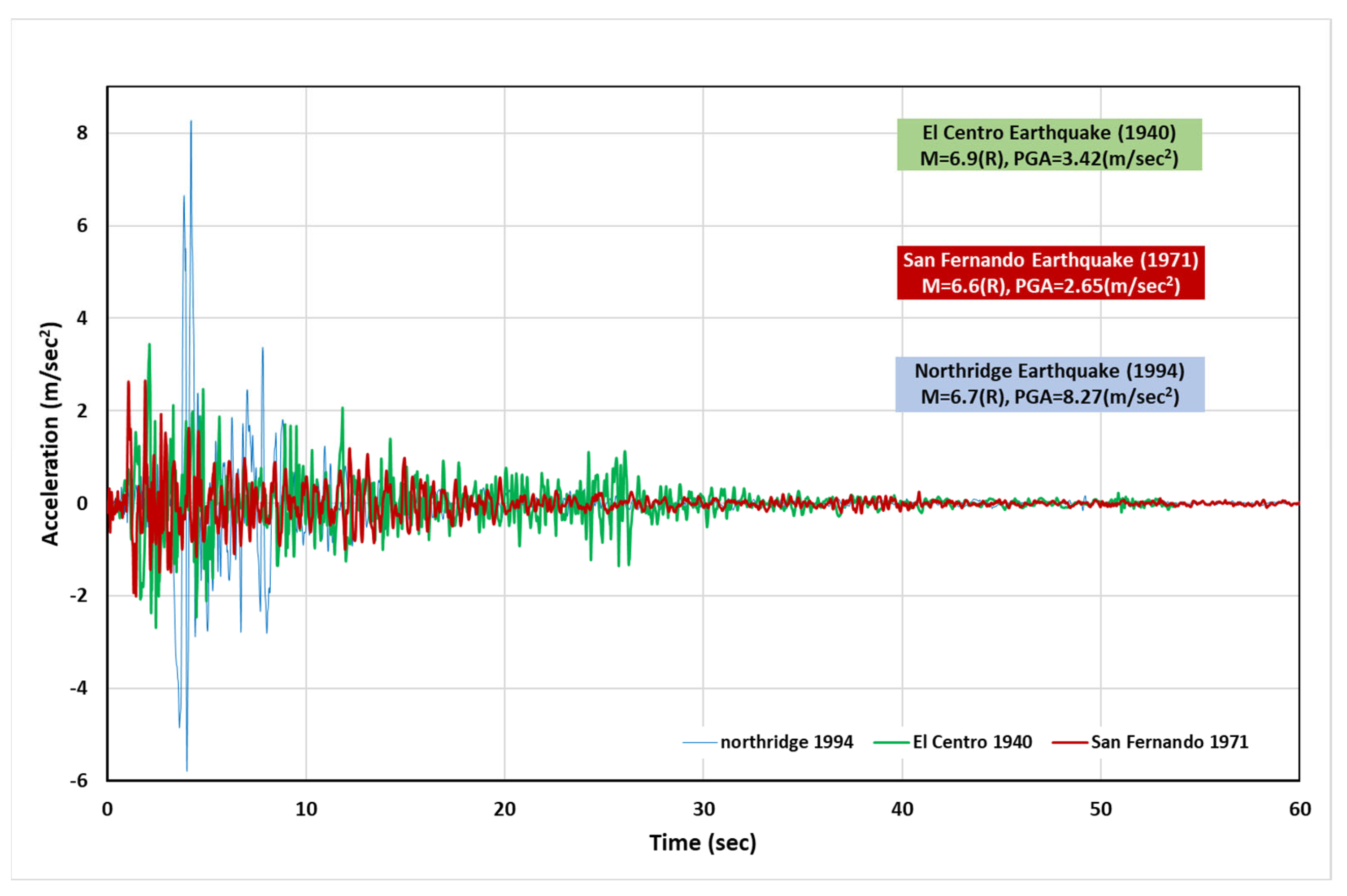
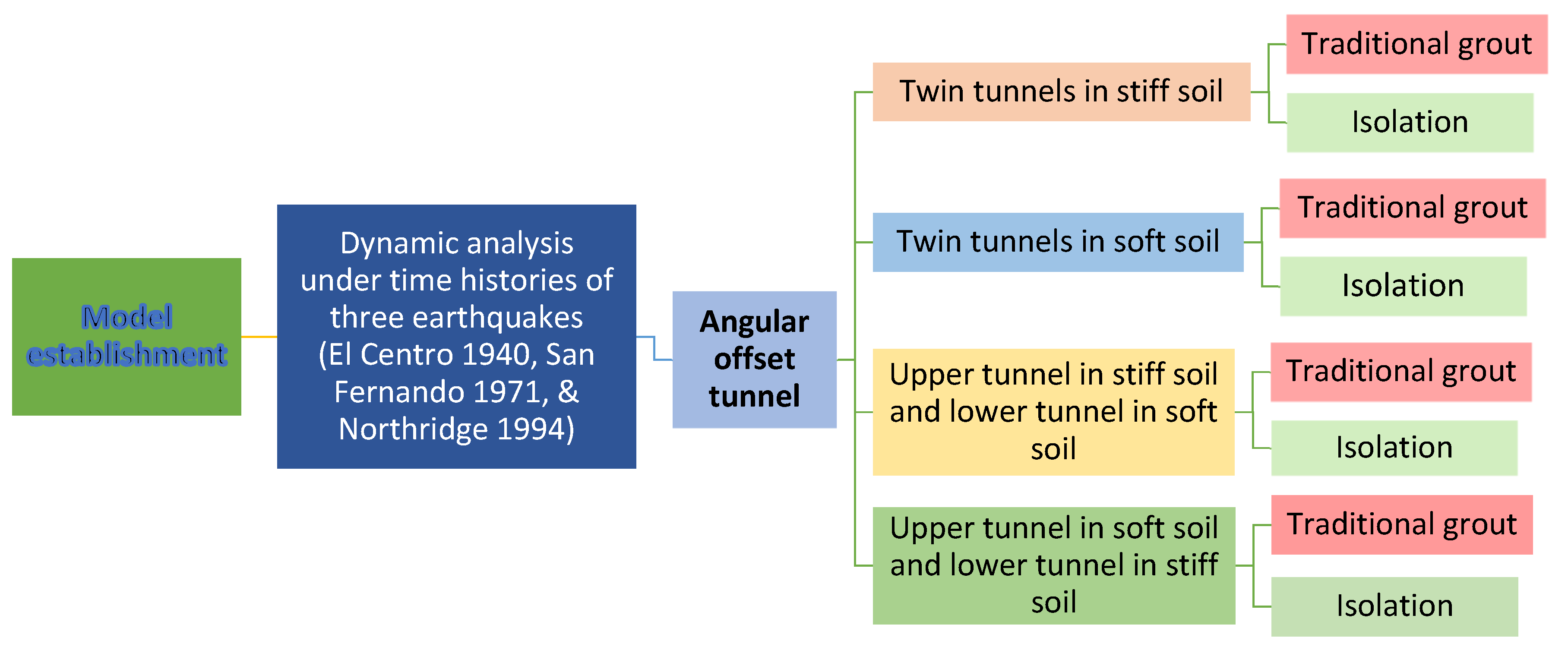
3.1. Model Establishment
3.2. Model Development
4. Results and Discussion
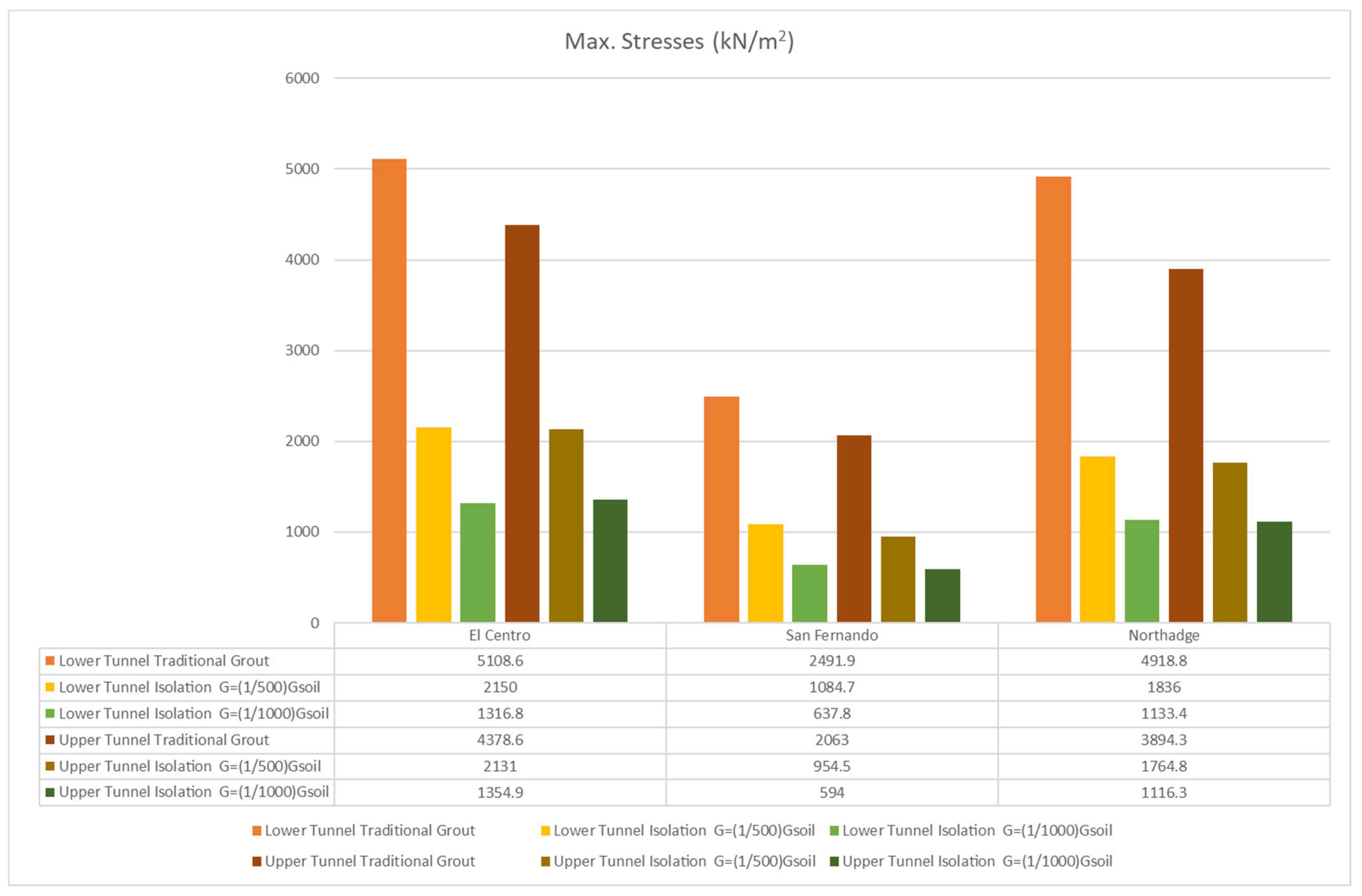
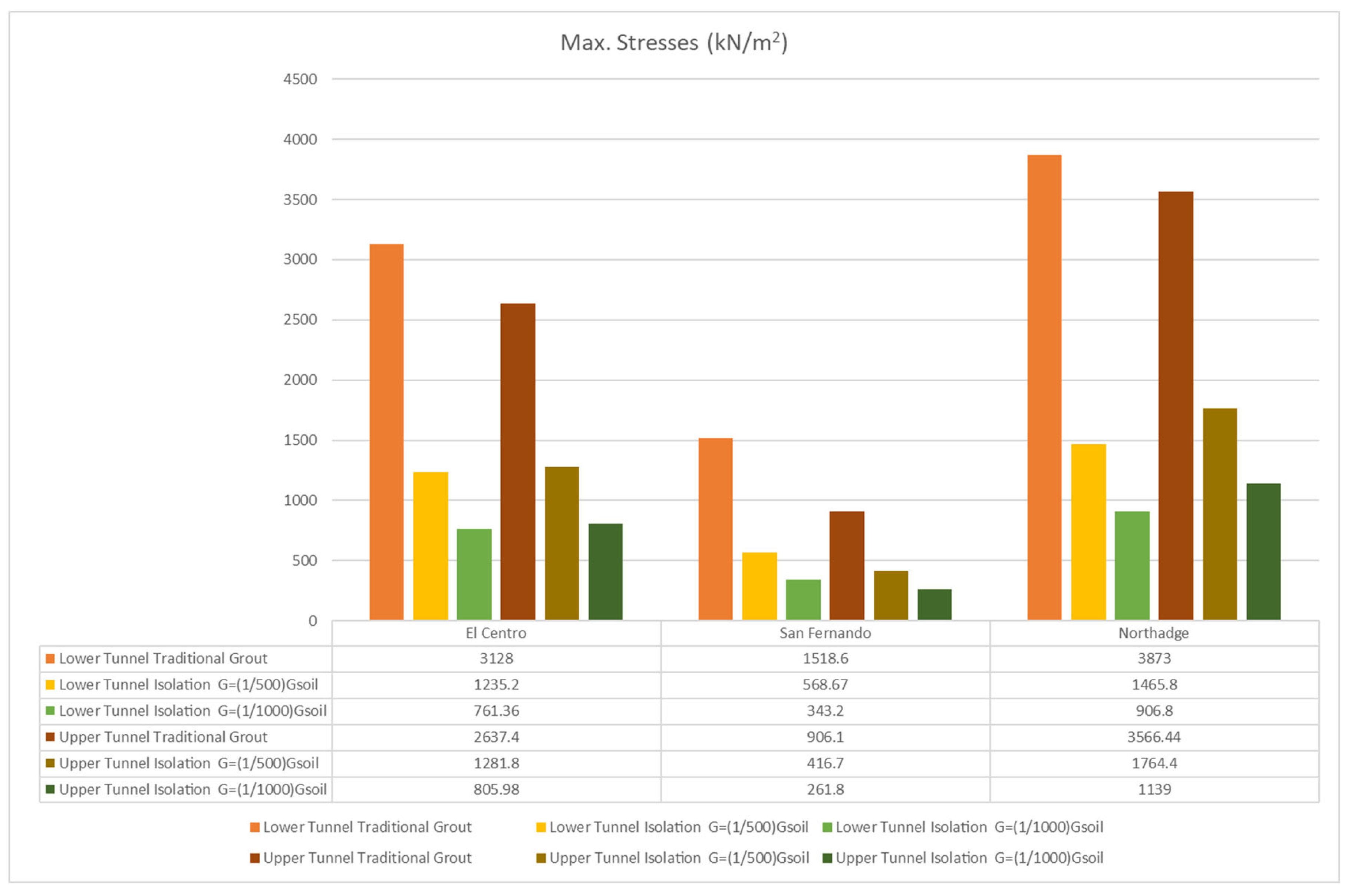
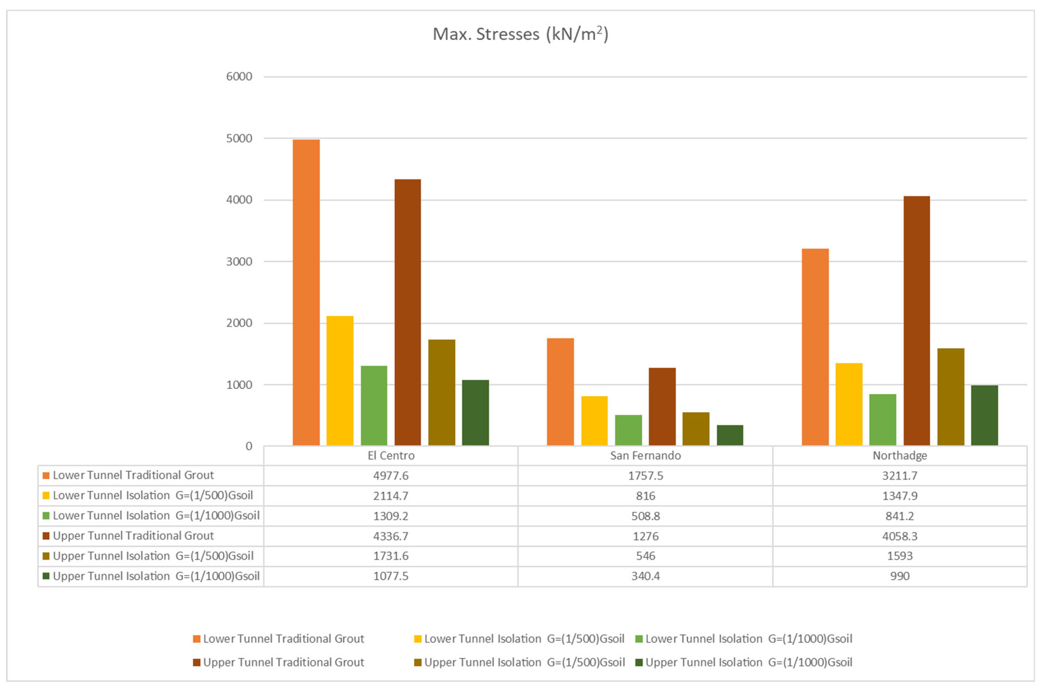
- In the case where both tunnels are in stiff soil, the average stress decreases by 51.3–76.9% when using isolation instead of traditional grout.
- In the case where both tunnels are in soft soil, the average stress decreases by 50.5–77.4% when using isolation instead of traditional grout.
- In the case where the upper tunnel is in soft soil, and the lower tunnel is in stiff soil, the average stress decreases by 53.6–73.3% when using isolation instead of traditional grout.
- In the case where the upper tunnel is in stiff soil, and the lower tunnel is in soft soil, the average stress decreases by 44.2–79.4% when using isolation instead of traditional grout.
- 1.
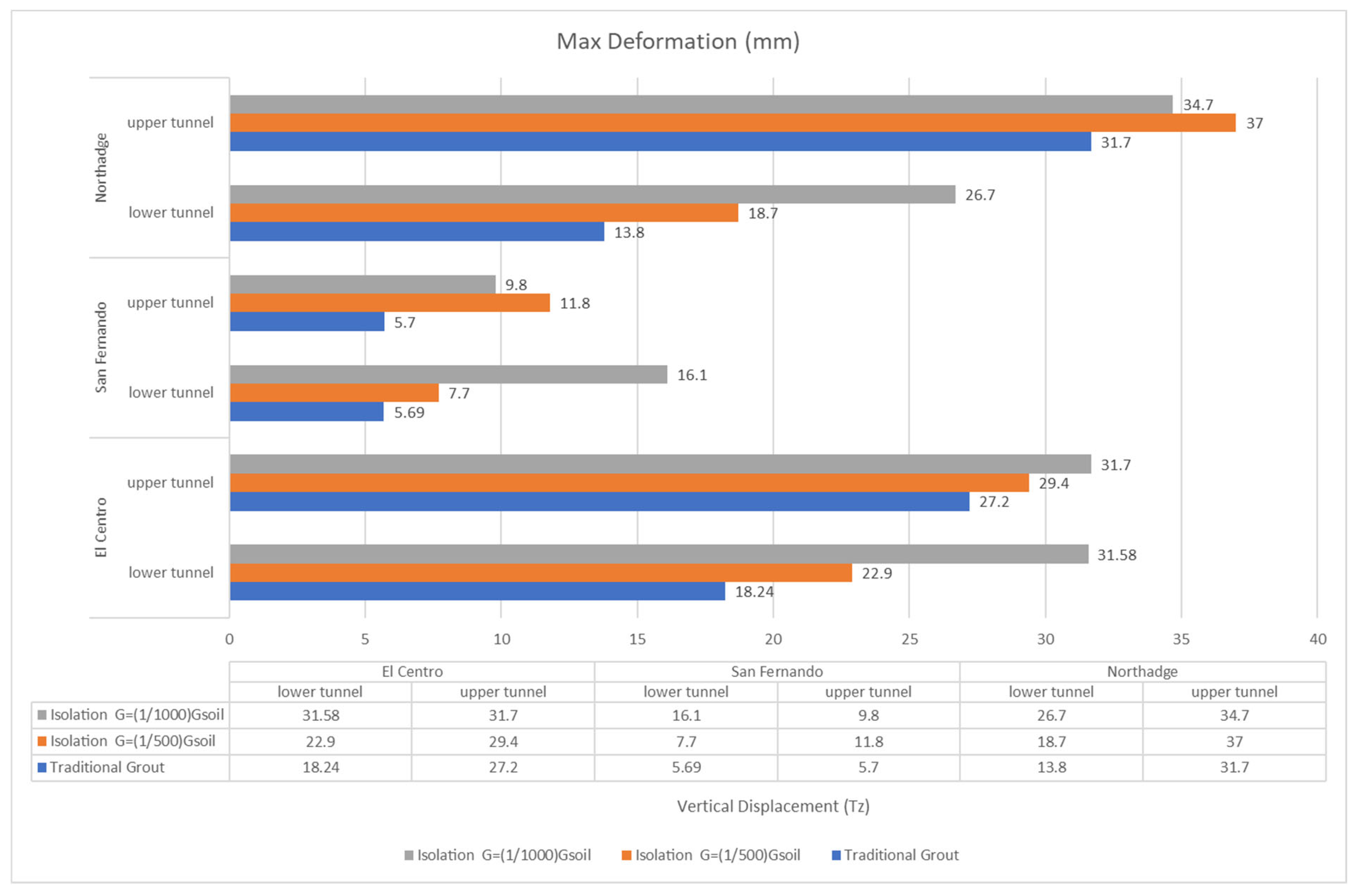
- When both tunnels are in stiff soil, the maximum vertical displacement increases by an average of 23.0% when using and 36.0% when using for the upper tunnel and by 14.0–23.0%, respectively, for the lower tunnel.
- 2.
- When both tunnels are in soft soil, the maximum vertical displacement increases by an average of 17.0% when using and 17.0% when using for the upper tunnel and by 36.0–93.0%, respectively, for the lower tunnel.
- 3.
- The maximum is when the upper tunnel is buried in soft soil and the lower tunnel in stiff soil. Vertical displacement increases by an average of 9.0% when using and 11.0% when using for the upper tunnel and by 46.0–109.0%, respectively, for the lower tunnel.
- 4.
- The maximum is when the upper tunnel is in stiff soil, and the lower tunnel is in soft soil. Vertical displacement increases by an average of 10.0% when using and 35.0% when using for the upper tunnel and by 7.0–34.0%, respectively, for the lower tunnel.
5. Conclusions
Author Contributions
Funding
Institutional Review Board Statement
Informed Consent Statement
Data Availability Statement
Conflicts of Interest
References
- Tunnel Market Survey, 2016—Tunnel (n.d.). Available online: https://www.tunnel–online.info/en/artikel/tunnel_Tunnel_Market_Survey_2016_3051818.html (accessed on 15 January 2020).
- Dowding, C.H.; Rozan, A. Damage to rock tunnels from earthquake shaking. J. Geotech. Eng. Div. 1978, 104, 175–191. [Google Scholar] [CrossRef]
- Yoshikawa, K.; Fukuchi, G. Earthquake damage to railway tunnels in Japan. Adv. Tunn. Technol. Subsurf. Use 1984, 4, 75–83. [Google Scholar]
- Wang, J.M. The distribution of earthquake damage to underground facilities during the 1976 Tang–Shan earthquake. Earthq. Spectra 1985, 1, 741–757. [Google Scholar]
- Wang, J.N. Seismic Design of Tunnels: A Simple State of the Art Design Approach; Parsons Brinckerhoff Inc.: New York, NY, USA, 1993. [Google Scholar]
- Iida, H.; Hiroto, T.; Yoshida, N.; Iwafuji, M. Damage to Daikai subway station. Soils Found. 1996, 36, 283–300. [Google Scholar] [CrossRef]
- An, X.; Shawky, A.; Maekawa, K. The collapse mechanism of a subway station during the Great Hanshin earthquake. Cem. Concr. Compos. 1997, 19, 241–257. [Google Scholar] [CrossRef]
- Huo, H.; Bobet, A.; Fernández, G.; Ramírez, J. Load transfer mechanisms between underground structure and surrounding ground: Evaluation of the failure of the Daikai station. J. Geotech. Geoenviron. Eng. 2005, 131, 1522–1533. [Google Scholar] [CrossRef]
- Montesinos, G.J.P.; Bobet, A.; Ramírez, J.A. Evaluation of soil–structure interaction and structural collapse in Daikai station. ACI Struct. J. 2006, 103, 113–122. [Google Scholar]
- Kontoe, S.; Zdravkovic, L.; Potts, D.; Mentiki, C. Case study on seismic tunnel response. Can. Geotech. J. 2008, 45, 1743–1764. [Google Scholar] [CrossRef] [Green Version]
- Yu, H.T.; Chen, J.T.; Yuan, Y.; Zhao, X. Seismic damage of mountain tunnels during the 5.12 Wenchuan earthquake. J. Mt. Sci. 2016, 13, 1958–1972. [Google Scholar] [CrossRef]
- Huo, H.; Bobet, A.; Fernández, G.; Ramírez, J. Analytical solution for deep rectangular structures subjected to far–field shear stresses. Tunn. Undergr. Space Technol. 2006, 21, 613–625. [Google Scholar] [CrossRef]
- Kontoe, S.; Zdravkovic, L.; Potts, D.; Mentiki, C. On the relative merits of simple and advanced constitutive models in dynamic analysis of tunnels. Geotechnique 2011, 61, 815–829. [Google Scholar] [CrossRef] [Green Version]
- Kampas, G.; Knappett, J.A.; Brown, M.J.; Anastasopoulos, I.; Nikitas, N.; Fuentes, R. The effect of tunnel lining modelling approaches on the seismic response of sprayed concrete tunnels in coarse–grained soils. Soil Dyn. Earthq. Eng. 2019, 117, 122–137. [Google Scholar] [CrossRef]
- Sedarat, H.; Kozak, A.; Hashash, Y.M.A.; Shamsabadi, A.; Krimotat, A. Contact interface in seismic analysis of circular tunnels. Tunn. Undergr. Space Technol. 2009, 24, 482–490. [Google Scholar] [CrossRef]
- Kouretzis, G.; Sloan, S.; Carter, J. Effect of interface friction on tunnel liner internal forces due to seismic S– and P–wave propagation. Soil Dyn. Earthq. Eng. 2013, 46, 41–51. [Google Scholar] [CrossRef]
- Kutter, B.L.; Chou, J.C.; Travasarou, T. Centrifuge testing of the seismic performance of a submerged cut and cover tunnel in liquefiable soils. In Proceedings of the Fourth Geotechnical Earthquake Engineering and Soils Dynamics Conference (GEESDC), Sacramento, CA, USA, 18–22 May 2008. [Google Scholar]
- Chou, J.C.; Kutter, B.L.; Travasarou, T.; Chacko, J.M. Centrifuge modeling of seismically induced uplift for the BART transbay tube. J. Geotech. Geoenviron. Eng. 2010, 137, 754–765. [Google Scholar] [CrossRef]
- Lanzano, G.; Bilotta, E.; Russo, G.; Silvestri, F.; Madabhushi, S.P.G. Dynamic centrifuge tests on shallow tunnel models in dry sand. In Physical Modelling in Geotechnics, Two Volume Sets; CRC Press: Boca Raton, FL, USA, 2010; pp. 561–567. [Google Scholar]
- Lanzano, G.; Bilotta, E.; Russo, G.; Silvestri, F.; Madabhushi, S.P.G. Centrifuge modelling of seismic loading on tunnels in sand. Geotech. Test. J. 2012, 35, 854–869. [Google Scholar] [CrossRef]
- Amorosi, A.; Boldini, D.; Falcone, G. Numerical prediction of tunnel performance during centrifuge dynamic tests. Acta Geotech. 2014, 9, 581–596. [Google Scholar] [CrossRef]
- Conti, R.; Viggiani, G.M.B.; Perugini, F. Numerical modelling of centrifuge dynamic tests of circular tunnels in dry sand. Acta Geotech. 2014, 9, 597–612. [Google Scholar] [CrossRef] [Green Version]
- Tsinidis, G.; Pitilakis, K.; Trikalioti, A.D. Numerical simulation of round–robin numerical test on tunnels using a simplified kinematic hardening model. Acta Geotech. 2014, 9, 641–659. [Google Scholar] [CrossRef]
- Tsinidis, G.; Pitilakis, K.; Madabhushi, G.; Heron, C. Dynamic response of flexible square tunnels: Centrifuge testing and validation of existing design methodologies. Géotechnique 2015, 65, 401–417. [Google Scholar] [CrossRef] [Green Version]
- Tsinidis, G.; Heron, C.; Pitilakis, K.; Madabhushi, G. Centrifuge modelling of the dynamic behavior of square tunnels in sand. In Experimental Research in Earthquake Engineering; Taucer, F., Apostolska, R., Eds.; Geotechnical and Geological Earthquake Engineering; Springer: Cham, Switzerland, 2015; Volume 35, pp. 509–523. [Google Scholar]
- Tsinidis, G.; Rovithis, E.; Pitilakis, K.; Chazelas, J.L. Dynamic response of shallow rectangular tunnels in sand by centrifuge testing. In Experimental Research in Earthquake Engineering; Taucer, F., Apostolska, R., Eds.; Geotechnical and Geological Earthquake Engineering; Springer: Cham, Switzerland, 2015; Volume 35, pp. 493–507. [Google Scholar]
- Tsinidis, G.; Pitilakis, K.; Madabhushi, G. On the dynamic response of square tunnels in sand. Eng. Struct. 2016, 125, 419–437. [Google Scholar] [CrossRef] [Green Version]
- Tsinidis, G.; Rovithis, E.; Pitilakis, K.; Chazelas, J.L. Seismic response of box–type tunnels in soft soil: Experimental and numerical investigation. Tunn. Undergr. Space Technol. 2016, 59, 199–214. [Google Scholar] [CrossRef]
- Esmaeilzadeh Seylabi, E.; Jeong, C.; Dashti, S.; Hushmand, A.; Taciroglu, E. Seismic response of buried reservoir structures: A comparison of numerical simulations with centrifuge experiments. Soil Dyn. Earthq. Eng. 2018, 109, 89–101. [Google Scholar] [CrossRef]
- Hashash, Y.M.A.; Dashti, M.S.; Michael Musgrove, S.M.; Gillis, K.; Martin Walker, M.; Kirk Ellison, M.; Basarah, S.M.Y.I. Influence of tall buildings on seismic response of shallow underground structures. J. Geotech. Geoenviron. Eng. 2018, 144, 04018097. [Google Scholar] [CrossRef]
- Tsinidis, G.; de Silva, F.; Anastasopoulos, I.; Bilotta, E.; Bobet, A.; Hashash, Y.M.; He, C.; Kampas, G.; Knappett, J.; Madabhushi, G.; et al. Seismic behaviour of tunnels: From experiments to analysis. Tunn. Undergr. Space Technol. 2020, 99, 103334. [Google Scholar] [CrossRef]
- Zucca, M.; Valente, M. On the limitations of decoupled approach for the seismic behaviour evaluation of shallow multi–propped underground structures embedded in granular soils. Eng. Struct. 2020, 211, 110497. [Google Scholar] [CrossRef]
- FHWA (Federal Highway Administration). Technical manual for design and construction of road tunnels–Civil elements. In Publication No. FHWA–NHI–10–034; Department of transportation, Federal Highway Administration: Washington, DC, USA, 2009. [Google Scholar]
- Zucca, M.; Crespi, P.G.; Tropeano, G.; Erbì, E. 2D equivalent linear analysis for the seismic vulnerability evaluation of multi–propped retaining structures. In Proceedings of the XVII ECSMGE–2019, Reykjavík, Iceland, 1–6 September 2019; pp. 1–6. [Google Scholar]
- Kampas, G.; Knappett, J.A.; Brown, M.J.; Anastasopoulos, I.; Nikitas, N.; Alonso–Rodriquez, A.; Fuentes, R. Suitability of equivalent linear soil models for analysing the seismic response of a concrete tunnel. In Proceedings of the 16th European Conference of Earthquake Engineering, Thessaloniki, Greece, 18–20 June 2018. [Google Scholar]
- Hwang, J.H.; Lu, C.C. Seismic capacity assessment of old Sanyi railway tunnels. Tunn. Undergr. Space Technol. 2007, 22, 433–449. [Google Scholar] [CrossRef]
- Bilotta, E.; Madabhushi, S.P.G.; Silvestri, F. Editorial: Round Robin Tunnel Test (RRTT). Acta Geotech. 2014, 9, 561–562. [Google Scholar] [CrossRef] [Green Version]
- Tsinidis, G.; Heron, C.; Pitilakis, K.; Madabhushi, G. Physical modeling for the evaluation of the seismic behavior of square tunnels. In Seismic Evaluation and Rehabilitation of Structures, Geotechnical and Geological Earthquake Engineering; Ilki, A., Fardis, M., Eds.; Springer International Publishing: Cham, Switzerland, 2014; pp. 389–406. [Google Scholar]
- Tsinidis, G.; Pitilakis, K.; Anagnostopoulos, C. Circular tunnels in sand: Dynamic response and efficiency of seismic analysis methods at extreme lining flexibilities. Bull. Earthq. Eng. 2016, 14, 2903–2929. [Google Scholar] [CrossRef]
- Wang, C.J. Seismic racking of a dual–wall subway station box embedded in soft soil strata. Tunn. Undergr. Space Technol. 2011, 26, 83–91. [Google Scholar] [CrossRef]
- Hleibieh, J.; Wegener, D.; Herle, I. Numerical simulation of a tunnel surrounded by sand under earthquake using a hypoplastic model. Acta Geotech. 2014, 9, 631–640. [Google Scholar] [CrossRef]
- Gomes, R.C. Numerical simulation of the seismic response of tunnels in sand with an elastoplastic model. Acta Geotech. 2014, 9, 613–629. [Google Scholar] [CrossRef]
- Lanzano, G.; Bilotta, E.; Russo, G.; Silvestri, F. Experimental and numerical study on circular tunnels under seismic loading. Eur. J. Environ. Civil. Eng. 2015, 19, 539–563. [Google Scholar] [CrossRef]
- Abate, G.; Massimino, M.R.; Michele, M. Numerical modelling of centrifuge tests on tunnel–soil systems. Bull. Earthq. Eng. 2015, 13, 1927–1951. [Google Scholar] [CrossRef]
- Kheradi, H.; Ye, B.; Nishi, H.; Oka, R.; Zhang, F. Optimum pattern of ground improvement for enhancing seismic resistance of existing box culvert buried in soft ground. Tunn. Undergr. Space Technol. 2017, 69, 187–202. [Google Scholar] [CrossRef]
- Patil, M.; Choudhury, D.; Ranjith, P.G.; Zhao, J. Behavior of shallow tunnel in soft soil under seismic conditions. Tunn. Undergr. Space Technol. 2018, 82, 30–38. [Google Scholar] [CrossRef]
- Fabozzi, S.; Bilotta, E.; Picozzi, M.; Zollo, A. Feasibility study of a loss–driven earthquake early warning and rapid response systems for tunnels of the Italian high– speed railway network. Soil Dyn. Earthq. Eng. 2018, 112, 232–242. [Google Scholar] [CrossRef]
- Lu, C.C.; Hwang, J.H. Nonlinear collapse simulation of Daikai Subway in the 1995 Kobe earthquake: Necessity of dynamic analysis for a shallow tunnel. Tunn. Undergr. Space Technol. 2019, 87, 78–90. [Google Scholar] [CrossRef]
- Salemi, A.; Mikaeil, R.; Haghshenas, S.S. Integration of finite difference method and genetic algorithm to seismic analysis of circular shallow tunnels (Case study: Tabriz urban railway tunnels). KSCE J. Civ. Eng. 2018, 22, 1978–1990. [Google Scholar] [CrossRef]
- Ding, P.; Tao, L.; Yang, X.; Zhao, J.; Shi, C. Three–dimensional dynamic response analysis of a single–ring structure in a prefabricated subway station. Sustain. Cities Soc. 2019, 45, 71–286. [Google Scholar] [CrossRef]
- Mikaeil, R.; Bakhshinezhad, H.; Haghshenas, S.S.; Ataei, M. Stability analysis of tunnel support systems using numerical and intelligent simulations (case study: Kouhin Tunnel of Qazvin–Rasht Railway). Rud. Geološko Naft. Zb. 2019, 34, 11. [Google Scholar] [CrossRef] [Green Version]
- Al–Mirza, H.A.; Karkush, M.O. Numerical Modeling of Circular Tunnel Alignment Under Seismic Loading. In Geotechnical Engineering and Sustainable Construction; Springer: Singapore, 2022; pp. 15–27. [Google Scholar]
- Bobet, A.; Fakhimi, A.; Johnson, S.; Morris, J.; Tonon, F.; Yeung, M. Numerical Models in Discontinuous Media: A review of advances for rock mechanics applica– tions. ASCE J. Geotech. Geoenviron. Eng. 2009, 135, 1547–1561. [Google Scholar] [CrossRef]
- Power, M.; Rosidi, D.; Kaneshiro, J.; Gilstrap, S.; Chiou, S.J. Summary and evaluation of procedures for the seismic design of tunnels. In Final Report for Task 112–d–5. 3(c); National Center for Earthquake Engineering Research: Buffalo, NY, USA, 1998. [Google Scholar]
- Chen, Z.; Liang, S.; Shen, H.; He, C. Dynamic centrifuge tests on effects of isolation layer and cross–section dimensions on shield tunnels. Soil Dyn. Earthq. Eng. 2018, 109, 173–187. [Google Scholar] [CrossRef]
- Dowding, C.H. Seismic stability of underground openings. In Storage in Excavated Rock Caverns: Rockstore 77; Magnus Bergman, S., Ed.; Pergamon Press: Oxford, UK, 1978; Volume 77, pp. 231–238. [Google Scholar]
- Owen, G.N.; Scholl, R.E. Earthquake engineering of large underground structures. In Report No. FHWA/RD–80/195; 1981; 279p. Available online: https://nehrpsearch.nist.gov/static/files/NSF/PB81247918.pdf (accessed on 25 February 2020).
- Sharma, S.; Judd, W.R. Underground opening damage from earthquakes. Eng. Geol. 1991, 30, 263–276. [Google Scholar] [CrossRef]
- Asakura, T.; Sato, Y. Damage to mountain tunnels in hazard area. Soils Found. 1996, 36, 301–310, (Special Issue). [Google Scholar] [CrossRef]
- Asakura, T.; Sato, Y. Mountain tunnels damage in the 1995 Hyogoken–nanbu Earthquake. Quart. Rep. RTRI 1998, 39, 9–16. [Google Scholar]
- Yashiro, K.; Kojima, Y.; Shimizu, M. Historical earthquake damage to tunnels in Japan and case studies of railway tunnels in the 2004 Niigataken–Chuetsu earth– quake. Quart. Rep. RTRI 2007, 48, 136–141. [Google Scholar] [CrossRef] [Green Version]
- Alderman, J.; Beardall, J.; Campbell, K.; Campbell, R.; Chang, S.; Cole, C.; David, K.; Goltz, J.; Gordon, B.; Lee, M.; et al. The January 17, 1995 Kobe earthquake: An EQE summary report. In EQE International; 1995. Available online: http://www.worldcat.org/title/january–17–1995–kobe–earthquake–an–eqe–summary–report/oclc/32635132 (accessed on 25 February 2020).
- Uenishi, K.; Sakurai, S. Characteristic of the vertical seismic waves associated with the 1995 Hyogo–ken Nanbu (Kobe), Japan earthquake estimated from the failure of the Daikai Underground Station. Earthq. Eng. Struct. Dyn. 2000, 29, 813–821. [Google Scholar] [CrossRef]
- Ma, C.; Lu, D.; Du, D. Seismic performance upgrading for underground structures by introducing sliding isolation bearings. Tunn. Undergr. Space Technol. 2019, 69, 187–202. [Google Scholar] [CrossRef]
- Matsuda, T.; Samata, S.; Iwatate, T. Seismic response analysis for a collapsed underground subway structure with intermediate columns. In The 1995 Hyogoken–Nambu Earthquake: Investigation into Damage to Civil Engineering Structures; Japan Society of Civil Engineers, Committee of Earthquake Engineering: Tokyo, Japan, 1996; pp. 277–285. [Google Scholar]
- Samata, S.; Ohuchi, H.; Matsuda, T. A study of the damage of subway structures during the 1995 Hanshin–Awaji earthquake. Cem. Concr. Compos. 1997, 19, 223–239. [Google Scholar] [CrossRef]
- Kawashima, K. Seismic design of underground structures in soft ground: A review. In Geotechnical Aspects of Underground Construction in Soft Ground; Fujita, K., Miyazaki, Eds.; Balkema: Rotterdam, The Netherlands, 2000. [Google Scholar]
- Kawashima, K. Seismic analysis of underground structures. J. Disaster Res. 2006, 1, 378–389. [Google Scholar] [CrossRef]
- Hashash, Y.M.A.; Hook, J.J.; Schmidt, B.; Yao, J.I.C. Seismic design and analysis of underground structures. Tunn. Undergr. Space Technol. 2001, 16, 247–293. [Google Scholar] [CrossRef]
- Chao, M.; Dechun, L.; Xiuli, D. Seismic performance upgrading for underground structures by introducing sliding isolation bearings. Tunn. Undergr. Sp. Tech. 2018, 74, 1–9. [Google Scholar]
- Ma, S.; Chen, W.; Zhao, W. Mechanical properties and associated seismic isolation effects of foamed concrete layer in rock tunnel. J. Rock Mech. Geotech. Eng. 2019, 11, 159–171. [Google Scholar] [CrossRef]
- Pitilakis, K.; Tsinidis, G.; Chalatis, A. Shallow immersed rectangular tunnel in soft soils. In ISO/TR 12930:2014 Seismic Design Examples Based on ISO 23459; International Organization for Standardization: Geneva, Switzerland, 2014. [Google Scholar]
- Ingerslev, C.; Kiyomiya, O. Earthquake analysis, immersed, and floating tunnels. Tunn. Undergr. Space Technol. 1997, 12, 157–162. [Google Scholar] [CrossRef]
- St John, C.M.; Zahrah, T.F. A seismic design of underground structures. Tunn. Undergr. Space Technol. 1987, 2, 165–197. [Google Scholar] [CrossRef]
- Paolucci, R.; Pitilakis, K. Seismic risk assessment of underground structures under transient ground deformations. In Earthquake Geotechnical Engineering; Pitilakis, K., Ed.; Springer Netherlands, 2007; Volume 6, pp. 433–459. Available online: https://www.springerprofessional.de/en/seismic-risk-assessment-of-underground-structures-under-transien/1579134 (accessed on 25 February 2020).
- Pitilakis, K.; Tsinidis, G. Performance and seismic design of underground structures. In Earthquake Geotechnical Engineering Design; Springer: Cham, Switzerland, 2014; pp. 279–340. [Google Scholar]
- ISO 23469; Bases for Design of Structures—Seismic Actions for Designing Geotechnical Works, International Standard ISO TC98/SC3/WG10. International Organization for Standardization: Geneva, Switzerland, 2005.
- Anastasopoulos, I.; Gerolymos, N.; Drosos, V.; Georgarakos, T.; Kourkoulis, R.; Gazetas, G. Behaviour of deep immersed tunnel under combined normal fault rupture deformation and subsequent seismic shaking. Bull. Earthq. Eng. 2008, 6, 213–239. [Google Scholar] [CrossRef]
- Thewes, M.; Budach, C. Grouting of the annular gap in shield tunnelling—An important factor for minimisation of settlements and production performance. In Proceedings of the ITA–AITES World Tunnel Congress, Budapest, Hungary, 26 May 2009. [Google Scholar]
- Kuhlemeyer, R.L.; Lysmer, J. Finite element method accuracy for wave propagation problems. J. Soil Mech. Found. Div. 1973, 99, 421–427. [Google Scholar] [CrossRef]
- Shimamura, S.; Kasai, H.; Haruumi, M. Seismic isolation effect for a tunnel with a soft isolation layer. Struct. Eng. Earthq. Eng. 1999, 16, 43s–154s. [Google Scholar] [CrossRef] [Green Version]
- Kim, D.S.; Konagai, K. Seismic isolation effect of a tunnel covered with coating material. Tunn. Undergr. Space Technol. 2000, 15, 437–443. [Google Scholar] [CrossRef]
- Li, C.; Chen, W. Seismic isolation effect of foamed concrete layer along the longitudinal direction of a mountainous tunnel. Vibroeng. Procedia 2019, 23, 76–80. [Google Scholar] [CrossRef]



| Item No. | Description |
|---|---|
| 1 | Low shear modulus and high shear deformability |
| 2 | High durability, long-term stability, and small volumetric changes |
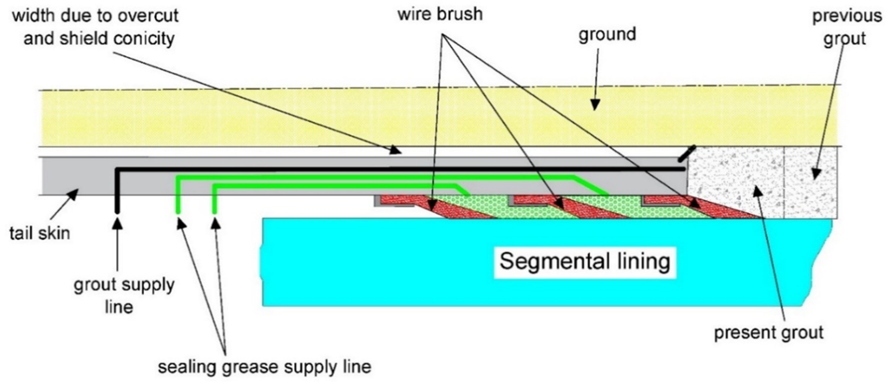
| 3 | High construction ability (i.e., for shield-driving tunnels, transportability by pumping in a liquid state and high filling-up performance) |
| 4 | Water tightness |
| 5 | No dilution by groundwater |
| 6 | No contaminants |
| Construction Method | Isolation Material | Material Contacts |
|---|---|---|
| Shield-driving tunnel | Asphalt-based material | Asphalt and Portland cement with high-water-absorbing polymer |
| Urethane-based material | Urethane with fly ash and polymer | |
| Silicon-based material | Silicon oil and fly ash with polyether |
| Material | Modulus of Elasticity (E) (kN/m2) | Poisson’s Ratio (ν) | Unit Weight (γ) (kN/m3) | Cohesion (cu) (kN/m2) | Friction Angle (φ) (0) |
|---|---|---|---|---|---|
| Soft clay | 25,000 | 0.48 | 19.00 | 30.00 | 0.00 |
| Stiff clay | 75,000 | 0.45 | 20.00 | 60.00 | 0.00 |
| Lower sand | 90,000 | 0.35 | 20.00 | 0.00 | 38.00 |
| Material | Modulus of Elasticity (E) (kN/m2) | Poisson’s Ratio (ν) | Unit Weight (γ) (kN/m3) |
|---|---|---|---|
| Concrete for segment | 30 × 106 | 0.20 | 25.00 |
| Grout for tunnel in soft clay | 40,000 | 0.30 | 20.00 |
| Grout for tunnel in stiff clay | 100,000 | 0.30 | 20.00 |
| Material | Shear Modulus (G) (kN/m2) | Poisson’s Ratio (ν) | Unit Weight (γ) (kN/m3) |
|---|---|---|---|
| Isolation for tunnel in soft clay | 20/10 | 0.48 | 10.00 |
| isolation for tunnel in stiff clay | 50/25 | 0.48 | 10.00 |
| Tunnel Description | Isolation Shear Modulus | Lower Tunnel | Upper Tunnel | ||
|---|---|---|---|---|---|
| Compression (Minimum Stresses) | Tension (Maximum Stresses) | Compression (Minimum Stresses) | Tension (Maximum Stresses) | ||
| Twin tunnels in stiff soil | ––(73.0–74.9)% | ––(74.0–76.9)% | ––(70.4–71.4)% | ––(69.0–61.3)% | |
| ––(57.0–59.0)% | ––(56.5–62.7)% | ––(52.5–54.8)% | ––(51.3–54.7)% | ||
| Twin tunnels in soft soil | ––(72.9–77.3)% | ––(75.7–77.4)% | ––(68.9–71.0)% | ––(68.0–71.0)% | |
| ––(56.5–63.0)% | ––(60.5–62.6)% | ––(51.6–54.7)% | ––(50.5–54.0)% | ||
| Upper tunnel in soft soil and lower tunnel in stiff soil | ––(72.3–73.8)% | ––(71.0–73.7)% | ––(72.9–74.7)% | ––(73.3–75.6)% | |
| ––(55.5–57.5)% | ––(53.6–58.0)% | ––(57.0–59.4)% | ––(57.2–60.8)% | ||
| Upper tunnel in stiff soil and lower tunnel in soft soil | ––(77.2–79.4)% | ––(76.3–77.6)% | ––(63.8–64.6)% | ––(63.8–66.6)% | |
| ––(63.8–64.6)% | ––(61.8–63.3)% | –(44.8–44.0)% | –(44.2–47.5)% | ||
Publisher’s Note: MDPI stays neutral with regard to jurisdictional claims in published maps and institutional affiliations. |
© 2022 by the authors. Licensee MDPI, Basel, Switzerland. This article is an open access article distributed under the terms and conditions of the Creative Commons Attribution (CC BY) license (https://creativecommons.org/licenses/by/4.0/).
Share and Cite
Elgamal, A.; Elfaris, N. Adverse Impact of Earthquake Seismic Loading on Angular Offset Tunnels and Effects of Isolation Grout. Infrastructures 2022, 7, 87. https://doi.org/10.3390/infrastructures7070087
Elgamal A, Elfaris N. Adverse Impact of Earthquake Seismic Loading on Angular Offset Tunnels and Effects of Isolation Grout. Infrastructures. 2022; 7(7):87. https://doi.org/10.3390/infrastructures7070087
Chicago/Turabian StyleElgamal, Ahmed, and Nissreen Elfaris. 2022. "Adverse Impact of Earthquake Seismic Loading on Angular Offset Tunnels and Effects of Isolation Grout" Infrastructures 7, no. 7: 87. https://doi.org/10.3390/infrastructures7070087
APA StyleElgamal, A., & Elfaris, N. (2022). Adverse Impact of Earthquake Seismic Loading on Angular Offset Tunnels and Effects of Isolation Grout. Infrastructures, 7(7), 87. https://doi.org/10.3390/infrastructures7070087


