


Track Deterioration Model—State of the Art and Research Potentials


Abstract
:1. Introduction
- The model’s methodology is explained in Section 2.
- The motivation and aim can be found in Section 3.
- A declaration of the foundations and alternative/further approaches of the damage terms:
- A discussion of the future potential of each deterioration term is explored in Section 8.
- The conclusion is given in Section 9.
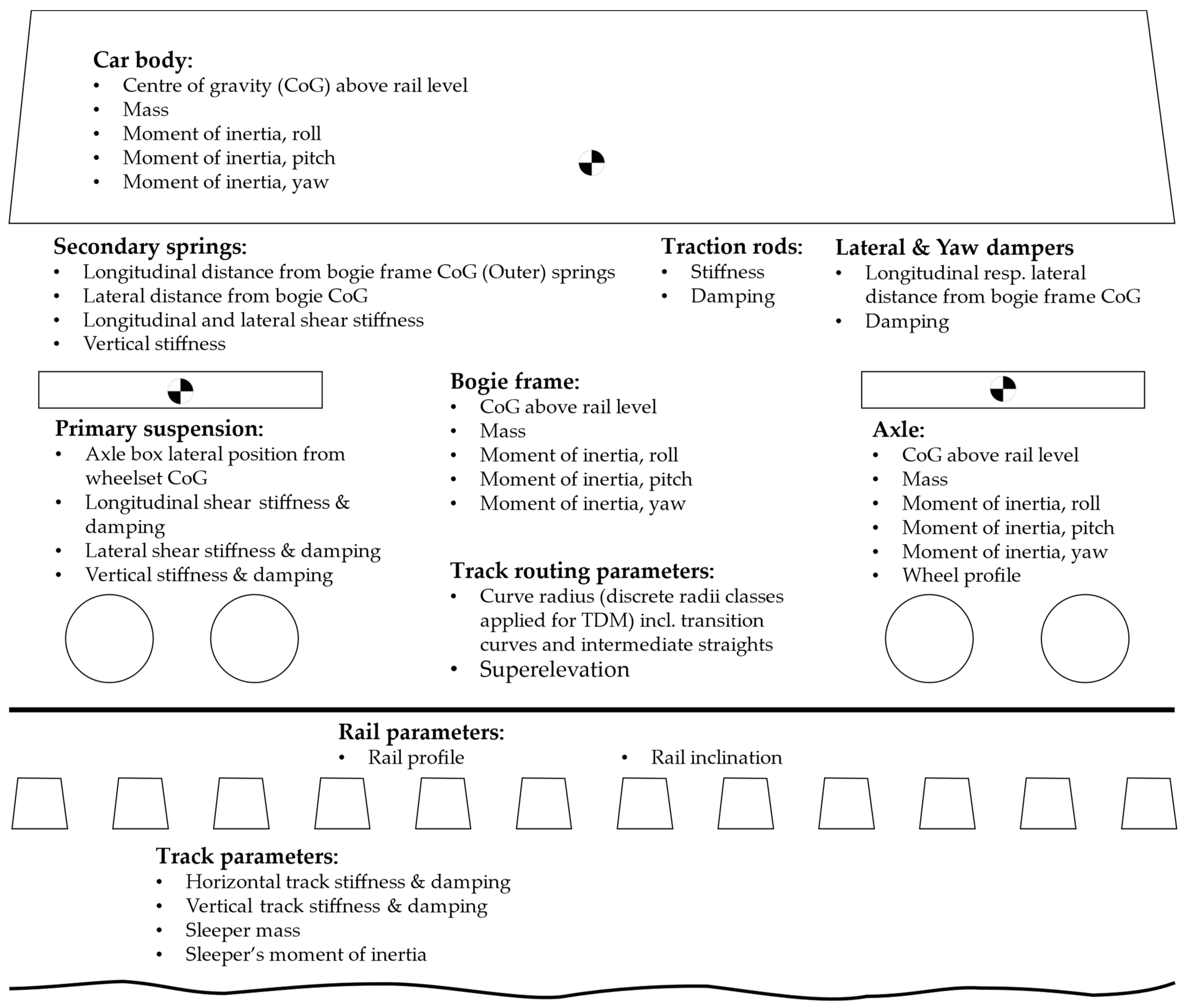
2. Methodology of the TUG Track Deterioration Model
| costs per vehicle kilometre depending on speed and radius | costs/km | |
| cost calibration factor (n = 1, 2, 3, 4.1, 4.2, 5, 6, 7) | costs/(km unit *) | |
| damage term (n = 1, 2, 3, 4.1, 4.2, 5, 6, 7) | Unit * | |
| dynamic vertical wheel force (long-waved) | kN | |
| dynamic vertical wheel force (short-waved) | kN | |
| lateral force of the guiding wheel on the outer rail within radius R | kN | |
| traction power value | kW/mm2 | |
| damage index for rolling contact fatigue (RCF) | - | |
| damage index for plastic deformation/rail abrasion | - | |
| weighting factor for vertical dynamic wheel force depending on radius R | - | |
| weighting factor for lateral wheel force depending on radius R | - | |
| * Unit of the damage term: kN3 for D1, D6 and D7, kN1.2 for D2, kW/mm2 for D3, kN for D5, and D4.1 and D4.2 are dimensionless | ||
- Vehicle:
- Number of vehicles going over track sections
- Number of powered and unpowered axles per vehicle
- Speed
- Unsprung mass
- Wheel radii
- Vertical forces
- Lateral forces
- Traction power
- Infrastructure:
- Radii
- Superstructure components and their masses, damping, and stiffness parameters
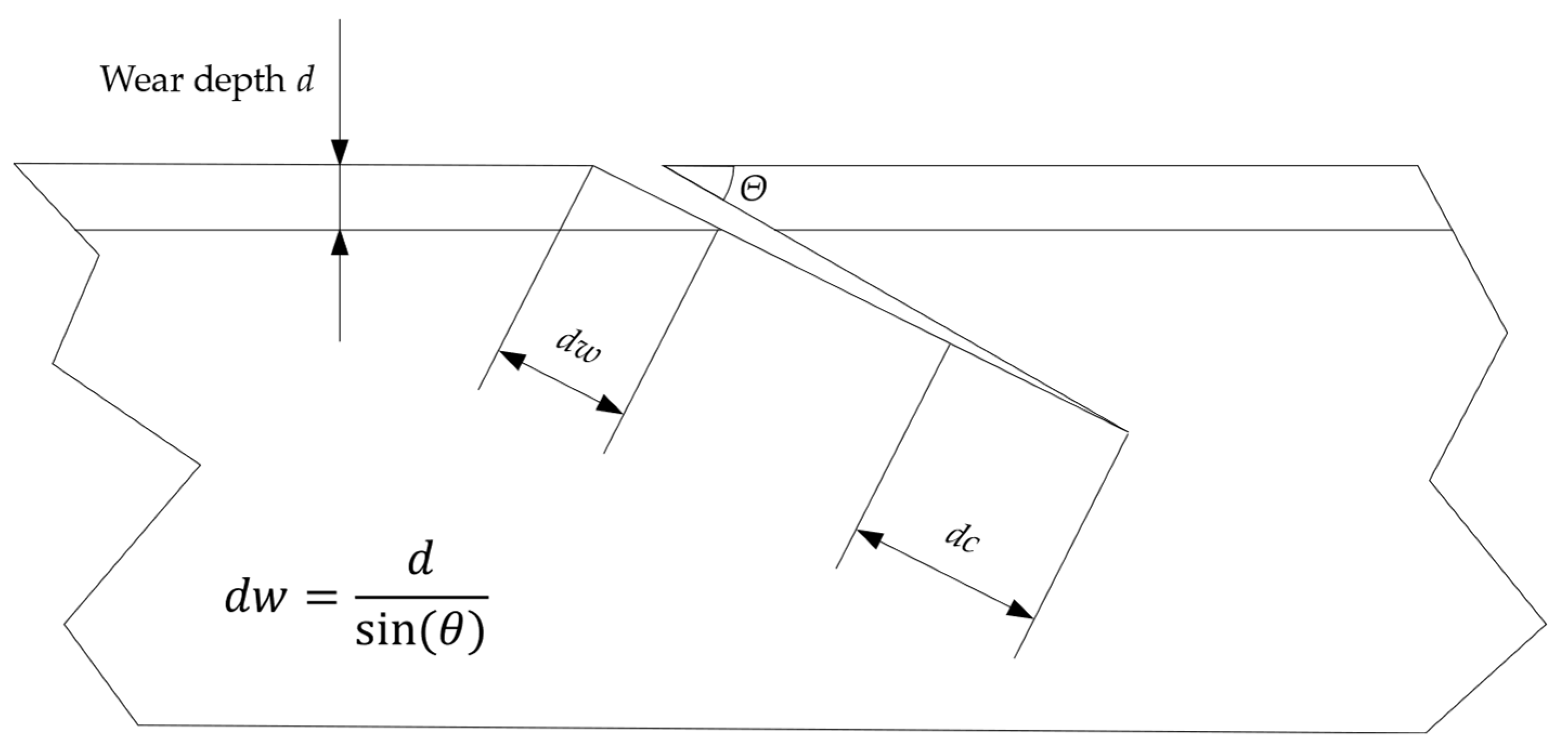
- Rail surface failure (angle)
- Maintenance:
- Average maintenance actions and costs by using standard elements [3]
- “What does a change in infrastructure components mean for the maintenance effort?”
- “What does a change in rolling stock (loco hauled vs. multiple units) mean for the maintenance effort?”
- “What does a change in the amount of trains mean for the maintenance effort?”
- “What does a change in axle load mean for the maintenance effort?”
- “What does a change in speed mean for the maintenance effort?”
- “What do irregularities in the superstructure or in rail surface (failure, insulated, or welded rail joints) mean for the maintenance effort?”
- (A)
- Which parameters have a significant impact on the associated track component?
- (B)
- Which of these parameters can be influenced and also described by an analytic approach?
3. Motivation and Aim of This Paper
4. Damage Term D1—Deterioration of Ballast and the Vertical Track Geometry (Straight and Curved Lines)
4.1. Functions of Ballast in the Track System
4.2. Causes and Dependencies of Ballast Deterioration
4.3. Foundations and Adaptions of D1
| damage term 1 for ballast deterioration | N3 | |
| dynamic vertical wheel force (long-waved) | N | |
| vehicle static wheel force | N | |
| relevant speed (limited by vehicle or track alignment) | m/s | |
| total joint angle | rad | |
| unsprung mass per vehicle wheel | kg | |
| effective vertical track mass per vehicle wheel | kg | |
| effective track damping per vehicle wheel | Ns/m | |
| effective track stiffness per vehicle wheel | N/m | |
| rail mass per unit length | kg/m | |
| mass of half a sleeper | kg | |
| ballast damping per sleeper end | Ns/m | |
| ballast stiffness per sleeper end | N/m | |
| sleeper spacing | m | |
| coefficient | 1/m | |
| rail bending stiffness | Nm2 |
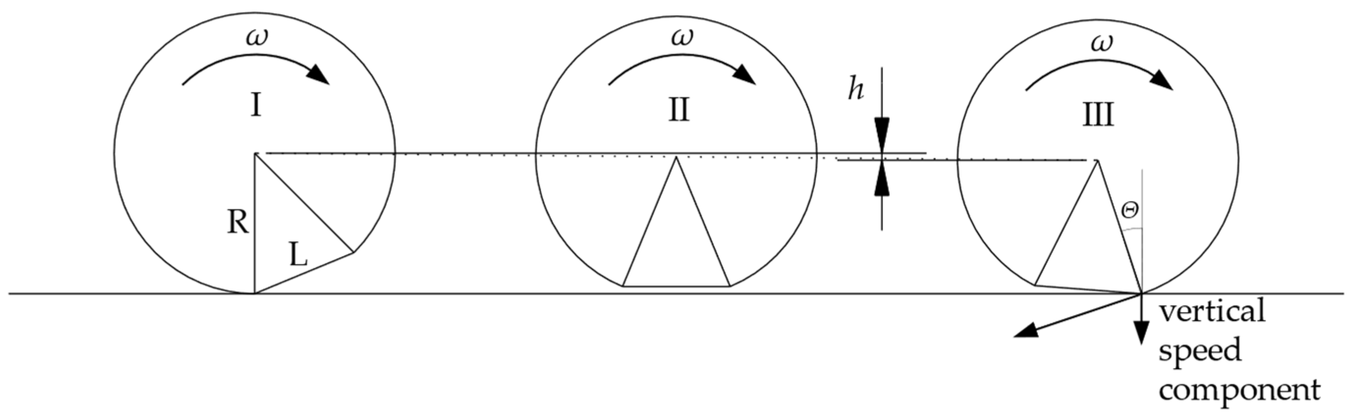
4.3.1. P2—Dynamic Vertical Wheel Force
- Infrastructure:
- Total joint angle
- Effective vertical track mass per vehicle wheel , Equation (6)
- Effective track damping per vehicle wheel , Equation (7)
- Effective track stiffness per vehicle wheel , Equation (8)
- Vehicle:
- Unsprung mass
- Speed
- The static wheel load should not exceed 125 kN or 0.13 × D (tread diameter D should not be less than 250 mm).
- A vehicle must be able to traverse a vertical ramp discontinuity in the rail top profile (e.g., dipped rail joint) on a straight track at its highest operational velocity. In this scenario, the force per wheel, comprising both static and dynamic components, does not exceed 322 kN.
| stiffness per sleeper end | N/m | |
| bedding modulus | N/m3 | |
| effective contact area between sleeper and ballast bed | m2 |
4.3.2. Superlinearity—Exponent 3
- Traffic load
- Representative dynamic wheel load
- Speed
- Quality index
- Maintenance costs for ballasted tracks
| quality level of a certain track quality parameter, e.g., longitudinal level | |
| value for the quality level corresponding to traffic load T | |
| value for the initial quality level (T = 0) | |
| calibration factor | |
| traffic load | |
| dynamic vertical wheel load | |
| speed | |
| maintenance costs | |
| exponents for parameter weighting | |
| index i (1, 2) describes different traffic scenarios that lead to different cost levels C |
5. Damage Term D2—Rail Surface Fatigue (Straight Lines)
5.1. Foundations of D2 (Force and Exponent Approach)
| D2 | damage term 2 for rail surface fatigue | N1.2 |
| dynamic vertical wheel force (long-waved) | N |
5.2. Alternative Description of the Dynamic Vertical Force Impact (Caused by Infrastructure)
| vehicle dynamic wheel forces | N | |
| vehicle static wheel force | N | |
| relevant speed (limited by vehicle or track alignment) | m/s | |
| total joint angle | rad | |
| unsprung mass per vehicle wheel | kg | |
| effective track mass per vehicle wheel | kg | |
| rail mass per unit length | kg/m | |
| mass of half a sleeper | kg | |
| sleeper spacing | m | |
| estimated vertical dynamic wheel force | N | |
| Hertzian flexibility constant (for worn tyre profiles) | m/N2/3 | |
| wheel radius | m | |
| linearised hertzian contact stiffness per vehicle wheel | N/m |
5.3. Vertical Force Impact (Caused by Vehicle)
| vertical force per vehicle wheel due to wheel flat | N | |
| vehicle static wheel force | N | |
| dropping distance of wheelset | m | |
| vehicle speed | m/s | |
| rotation speed | 1/s | |
| gravity acceleration | m/s2 | |
| length of wheel flat | m | |
| rolling radius | m | |
| angle | rad | |
| stiffness of rail pad | N/m | |
| stiffness of railroad bed incl. ballast, capping, and formation layer | N/m |
6. Damage Term D3—Rail Surface Wear (Straight Lines)
- Installed traction power .
- Static wheel force .
- Material properties: modulus of elasticity and Poisson’s ratio . It is assumed that these properties apply both to the wheel and the rail.
- Geometrical properties: radii of wheel and railhead .
- It is valid for homogeneous, isotropic material. This does not apply to the railhead due to the plastically deformed and aligned microstructure near the rail surface.
- It is conditioned on the validity of Hooke’s law. Thus, pure elastic deformation is assumed, which is not true in wheel–rail contact due to high contact pressure.
- It only considers the effect of normal stresses on the contact surface. This does not apply to the consideration of traction.
- It is valid for small deformation of both bodies in relation to body dimensions. This is true for wheel–rail contact.
7. Damage Term D4—Rail Surface Wear and Fatigue (Curved Lines)
- vehicle speed (to be chosen according to the curve radius, superelevation, and resulting free lateral acceleration, respectively), and
- coefficient of friction (assumption: constant coefficient of friction for whole simulation process, e.g., constant over time, location, and state of motion).
7.1. Damage, Forces, and Mechanisms
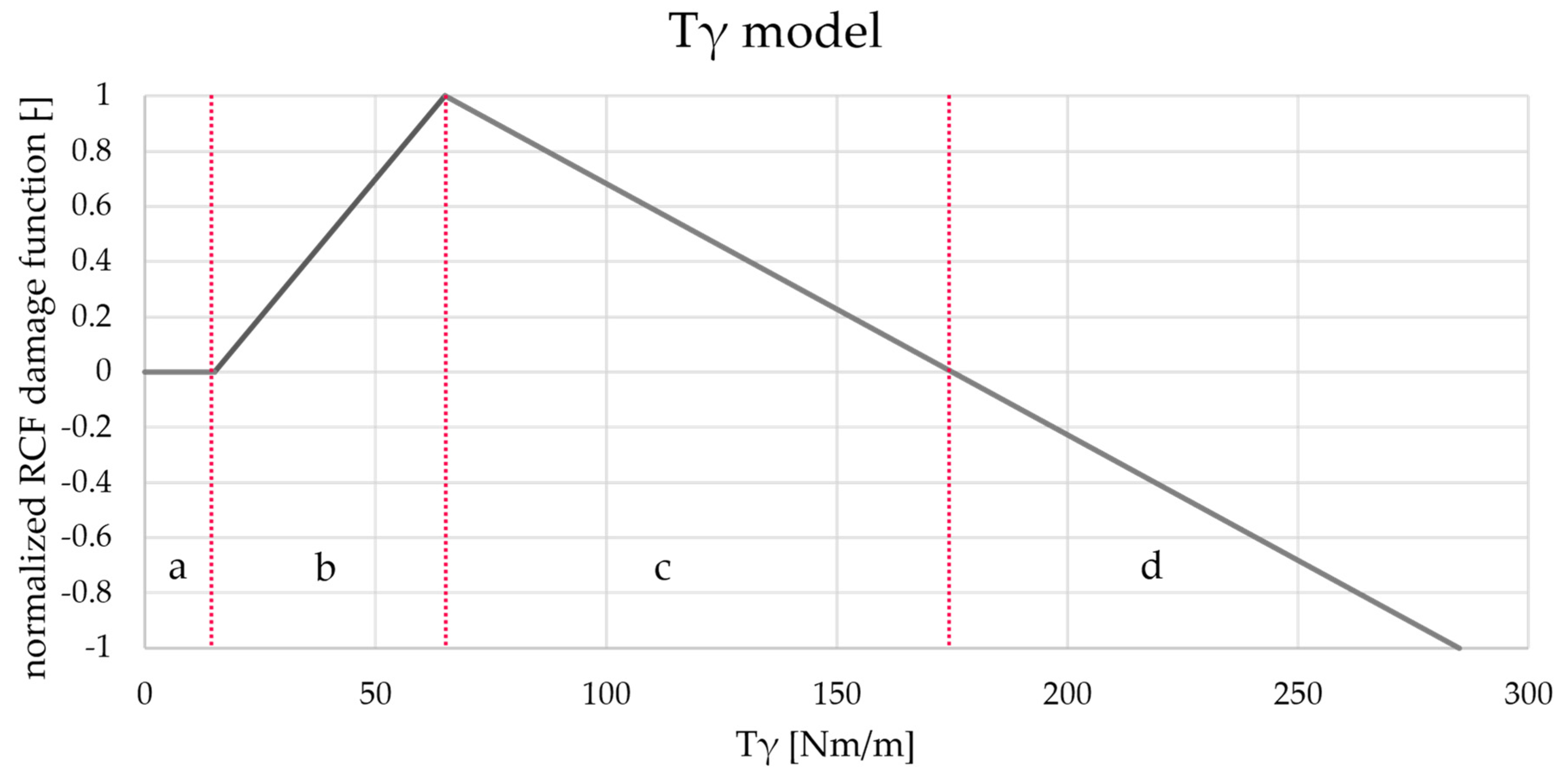
7.2. Foundations of D4—Tγ Model by Burstow
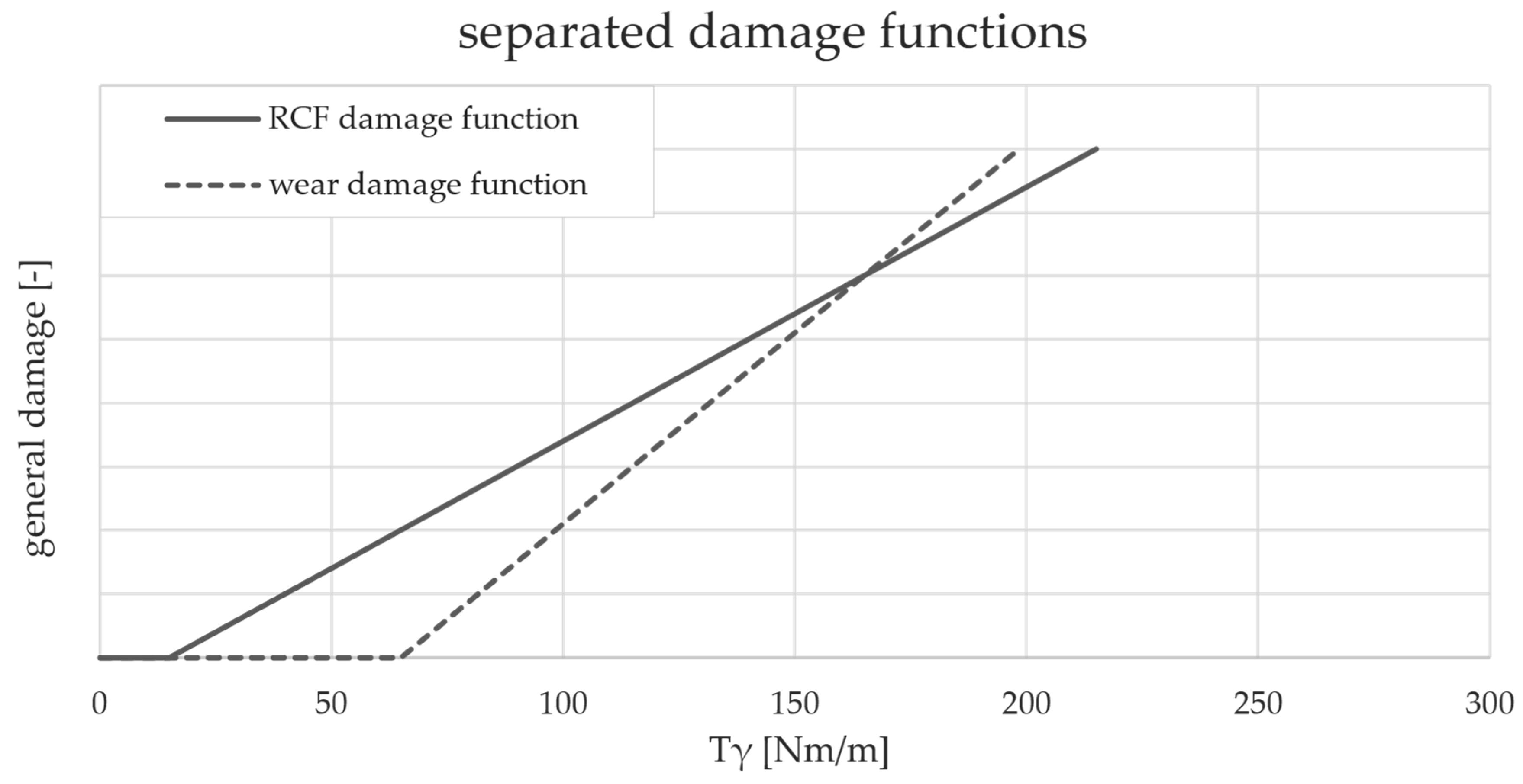
7.3. Burstow’s Model vs. TDM
7.4. Other Investigations
8. Discussion and Future Potentials
8.1. D1
8.2. D2
8.3. D3
- Integrating traction into the model and applying it to both straight and curved tracks could improve the assessment of rail damage.
- Investigations of alternative models that incorporate traction to assess rolling contact fatigue (RCF) and wear, such as those proposed by Six et al. [64], may offer improvements in combined damage assessment.
- Extending Hertzian theory to include rail deflection is an open research topic and offers a promising avenue for advancing the theoretical framework.
- Investigations of the influence of weather conditions, particularly the effect of water on adhesion levels, as emphasised by Buckley-Johnstone et al. [65], could provide valuable improvements in the assumption of friction coefficients and their behaviour.
8.4. D4 in General
8.4.1. D4.1—RCF Assessment
8.4.2. D4.2—Wear Assessment
8.5. Further Scope of Application
9. Conclusions
Author Contributions
Funding
Data Availability Statement
Conflicts of Interest
References
- Marschnig, S.; Ehrhart, U. Traffic Load and Its Impact on Track Maintenance. In New Research on Railway Engineering and Transport; IntechOpen: London, UK, 2023. [Google Scholar]
- FOT. Swiss Federal Office of Transport. Train Path Price. Available online: https://www.bav.admin.ch/bav/en/home/modes-of-transport/railways/informations-for-professionals/train-path-price.html (accessed on 13 February 2024).
- Marschnig, S.; Veit, P. Assessing Average Maintenance Frequencies and Service Lives of Railway Tracks: The Standard Element Approach. In New Research on Railway Engineering and Transportation; IntechOpen: London, UK, 2023. [Google Scholar]
- ÖBB-Infrastruktur AG. Target Network 2040—The Rail Network of the Future. Available online: https://infrastruktur.oebb.at/en/company/for-austria/future-rail-target-network (accessed on 19 February 2024).
- Jenkins, H.H.; Stephenson, J.E.; Clayton, G.A.; Morland, G.W.; Lyon, D. The Effect of Track and Vehicle Parameters on Wheel/Rail Vertical Dynamic Forces. Railw. Eng. J. 1974, 3, 2–16. [Google Scholar]
- ORE—Office of Research and Experiments. The Dynamic Effects Due to Increasing Axle Loads from 20 to 22.5 t, Question D161.1; Report No. 4; Int. Union of Railways: Utrecht, The Netherlands, 1978. [Google Scholar]
- Kuttelwascher, C. Track Ballast in Austria: Part 1–3. Available online: https://www.plasser.pl/fileadmin/user_upload/Media/Publikationen/ri_12888990.pdf (accessed on 13 April 2024).
- Indraratna, B.; Salim, W.; Rujikiatkamjorn, C. Advanced Rail Geotechnology—Ballasted Track; CRC Press: London, UK, 2011; ISBN 9780415669573. [Google Scholar]
- ÖNORM EN 13450; Aggregates for Railway Ballast. Austrian Standards Institute: Vienna, Austria, 2014.
- Shi, C.; Fan, Z.; Connolly, D.P.; Jing, G.; Markine, V.; Guo, Y. Railway ballast performance: Recent advances in the understanding of geometry, distribution and degradation. Transp. Geotech. 2023, 41, 101042. [Google Scholar] [CrossRef]
- Guo, Y.; Xie, J.; Fan, Z.; Markine, V.; Connolly, D.P.; Jing, G. Railway ballast material selection and evaluation: A review. Constr. Build. Mater. 2022, 344, 128218. [Google Scholar] [CrossRef]
- Zhou, T.Y.; Hu, B.; Yan, B.; Sun, J.F. Experimental and Numerical Study of Railway Ballast Compactness during Tamping Process. AMR 2013, 690–693, 2730–2733. [Google Scholar] [CrossRef]
- Zhou, T.; Hu, B.; Sun, J. Study of Railway Ballast Compactness under Tamping Operation. J. Appl. Sci. 2013, 13, 2072–2076. [Google Scholar] [CrossRef]
- Liu, J.; Wang, P.; Liu, G.; Xiao, J.; Liu, H.; Gao, T. Influence of a tamping operation on the vibrational characteristics and resistance-evolution law of a ballast bed. Constr. Build. Mater. 2020, 239, 117879. [Google Scholar] [CrossRef]
- Audley, M.; Andrews, J.D. The effects of tamping on railway track geometry degradation. Proc. Inst. Mech. Eng. Part F J. Rail Rapid Transit 2013, 227, 376–391. [Google Scholar] [CrossRef]
- Sol-Sánchez, M.; Moreno-Navarro, F.; Rubio-Gámez, M.C. Analysis of ballast tamping and stone-blowing processes on railway track behaviour: The influence of using USPs. Géotechnique 2016, 66, 481–489. [Google Scholar] [CrossRef]
- Zaayman, L. The Basic Principles of Mechanised Track Maintenance, 3rd ed.; PMC Media House GmbH: Bingen am Rhein, Germany, 2017; ISBN 9783962451516. [Google Scholar]
- Gu, Q.; Zhao, C.; Bian, X.; Morrissey, J.P.; Ooi, J.Y. Trackbed settlement and associated ballast degradation due to repeated train moving loads. Soil Dyn. Earthq. Eng. 2022, 153, 107109. [Google Scholar] [CrossRef]
- Stewart, H.E. Permanent Strains from Cyclic Variable-Amplitude Loadings. J. Geotech. Eng. 1986, 112, 646–660. [Google Scholar] [CrossRef]
- Indraratna, B.; Thakur, P.K.; Vinod, J.S. Experimental and Numerical Study of Railway Ballast Behavior under Cyclic Loading. Int. J. Geomech. 2010, 10, 136–144. [Google Scholar] [CrossRef]
- Diyaljee, V.A. Effects of Stress History on Ballast Deformation. J. Geotech. Eng. 1987, 113, 909–914. [Google Scholar] [CrossRef]
- ORE—Office of Research and Experiments. Optimum Adaptation of the Conventional Track to the Future Traffic, Question D117; Report No. 5; Int. Union of Railways: Utrecht, Netherlands, 1974. [Google Scholar]
- Bian, J.; Gu, Y.; Murray, M.H. A dynamic wheel–rail impact analysis of railway track under wheel flat by finite element analysis. Veh. Syst. Dyn. 2013, 51, 784–797. [Google Scholar] [CrossRef]
- Marschnig, S.; Ehrhart, U.; Offenbacher, S. Long-Term Behaviour of Padded Concrete Sleepers on Reduced Ballast Bed Thickness. Infrastructures 2022, 7, 132. [Google Scholar] [CrossRef]
- Mistry, P.J.; Johnson, M.S. Lightweighting of railway axles for the reduction of unsprung mass and track access charges. Proc. Inst. Mech. Eng. Part F J. Rail Rapid Transit 2020, 234, 958–968. [Google Scholar] [CrossRef]
- Mistry, P.J.; Johnson, M.S.; Li, S.; Bruni, S.; Bernasconi, A. Parametric sizing study for the design of a lightweight composite railway axle. Compos. Struct. 2021, 267, 113851. [Google Scholar] [CrossRef]
- Lee, W.G.; Kim, J.-S.; Sun, S.-J.; Lim, J.-Y. The next generation material for lightweight railway car body structures: Magnesium alloys. Proc. Inst. Mech. Eng. Part F J. Rail Rapid Transit 2018, 232, 25–42. [Google Scholar] [CrossRef]
- Schneider, P.; Bolmsvik, R.; Nielsen, J.C.O. In situ performance of a ballasted railway track with under sleeper pads. Proc. Inst. Mech. Eng. Part F J. Rail Rapid Transit 2011, 225, 299–309. [Google Scholar] [CrossRef]
- Paixão, A.; Alves Ribeiro, C.; Pinto, N.; Fortunato, E.; Calçada, R. On the use of under sleeper pads in transition zones at railway underpasses: Experimental field testing. Struct. Infrastruct. Eng. 2015, 11, 112–128. [Google Scholar] [CrossRef]
- GM/TT0088; Permissible Track Forces for Railway Vehicles, Revision A (Issue 1). British Rail Safety and Standards Board: London, UK, 1993.
- ÖNORM EN 14363; Railway Applications—Testing and Simulation for the Acceptance of Running Characteristics of Railway Vehicles—Running Behaviour and Stationary Tests. Austrian Standards Institute: Vienna, Austria, 2023.
- ÖBB-Infrastruktur AG. NONIs. Available online: https://infrastruktur.oebb.at/de/projekte-fuer-oesterreich/forschung-entwicklung/nonis (accessed on 26 February 2024).
- Lichtberger, B. Handbuch Gleis: Unterbau, Oberbau, Instandhaltung, Wirtschaftlichkeit; 3., Komplett Überarbeitete Neuauflage; Eurailpress: Hamburg, Germany, 2010; ISBN 9783777104003. [Google Scholar]
- Loy, H. Under sleeper pads in turnouts. Railw. Tech. Rev. 2009, 2, 35–38. [Google Scholar]
- Zhai, W.M.; Wang, K.Y.; Lin, J.H. Modelling and experiment of railway ballast vibrations. J. Sound Vib. 2004, 270, 673–683. [Google Scholar] [CrossRef]
- ORE—Office of Research and Experiments. Influence of Increasing the Axle Load from 20 to 22.5 t on the Superstructure, Question D141; Report No. 5; Int. Union of Railways: Utrecht, The Netherlands, 1982. [Google Scholar]
- Hertz, H. Über Die Berührung Fester Elastischer Körper. J. Für Die Reine Und Angew. Math. 1881, 171, 156–171. [Google Scholar]
- Timoshenko, S.; Goodier, J.N. Theory of Elasticity, 2nd ed.; McGraw-Hill Book Company, Inc.: New York, NY, USA, 1951. [Google Scholar]
- Villwock, J.; Hanau, A. Beanspruchung bei Berührung zweier Körper (Hertz’sche Formeln). In Dubbel Taschenbuch Für Den Maschinenbau 1: Grundlagen und Tabellen; Bender, B., Göhlich, D., Eds.; Springer Berlin Heidelberg: Berlin/Heidelberg, Germany, 2020; pp. 421–423. ISBN 978-3-662-59710-1. [Google Scholar]
- Telliskivi, T.; Olofsson, U. Contact Mechanics Analysis of Measured Wheel-Rail Profiles Using the Finite Element Method. Proc. Inst. Mech. Eng. Part F J. Rail Rapid Transit 2001, 215, 65–72. [Google Scholar] [CrossRef]
- Vollebregt, E.A.H. Numerical Modeling of Measured Railway Creep versus Creep-Force Curves with CONTACT. Wear 2014, 314, 87–95. [Google Scholar] [CrossRef]
- Burstow, M.C. Whole Life Rail Model Application and Development for RSSB—Continued Development of an RCF Damage Parameter; AEA Technology Rail: Derby, UK, 2004. [Google Scholar]
- Cannon, D.F.; Edel, K.O.; Grassie, S.L.; Sawley, K. Rail Defects: An Overview. Fatigue Fract. Eng. Mater. Struct. 2003, 26, 865–886. [Google Scholar] [CrossRef]
- Lewis, R.; Olofsson, U. Basic Tribology of the Wheel-Rail Contact. In Wheel–Rail Interface Handbook; Lewis, R., Olofsson, U., Eds.; Woodhead Publishing Limited: Cambridge, UK, 2009; ISBN 978-1-84569-412-8. [Google Scholar]
- Bolton, P.J.; Clayton, P. Rolling—Sliding Wear Damage in Rail and Tyre Steels. Wear 1984, 93, 145–165. [Google Scholar] [CrossRef]
- Grassie, S.L.; Elkins, J.A. Tractive Effort, Curving and Surface Damage of Rails. Wear 2005, 258, 1235–1244. [Google Scholar] [CrossRef]
- Grassie, S.L. Traction, Curving and Surface Damage of Rails, Part 2: Rail Damage. Proc. Inst. Mech. Eng. Part F J. Rail Rapid Transit 2015, 229, 330–339. [Google Scholar] [CrossRef]
- Kapoor, A.; Salehi, I.; Asih, A.M.S. Rolling Contact Fatigue (RCF). In Encyclopedia of Tribology; Wang, Q.J., Chung, Y.-W., Eds.; Springer US: Boston, MA, USA, 2013; pp. 2904–2910. ISBN 978-0-387-92896-8. [Google Scholar]
- Krishna, V.V.; Hossein-Nia, S.; Casanueva, C.; Stichel, S.; Trummer, G.; Six, K. Rail RCF damage quantification and comparison for different damage models. Rail. Eng. Sci. 2022, 30, 23–40. [Google Scholar] [CrossRef]
- Archard, J.F. Contact and Rubbing of Flat Surfaces. J. Appl. Phys. 1953, 24, 981–988. [Google Scholar] [CrossRef]
- Rabinowicz, E. Wear Coefficients—Metals. In Wear Control Handbook; Peterson, M.B., Winer, W.O., Eds.; ASME: New York, NY, USA, 1980; pp. 475–506. [Google Scholar]
- Rabinowicz, E. Friction and Wear of Self-Lubricating Metallic Materials. J. Lubr. Technol. 1975, 97, 217–220. [Google Scholar] [CrossRef]
- Rabinowicz, E. Friction and Wear; Wiley: New York, NY, USA, 1965. [Google Scholar]
- Rabinowicz, E. The Nature of the Static and Kinetic Coefficients of Friction. J. Appl. Phys. 1951, 22, 1373–1379. [Google Scholar] [CrossRef]
- Sommer, K.; Heinz, R.; Schöfer, J. Verschleiß Metallischer Werkstoffe; Springer Vieweg: Wiesbaden, German, 2018; ISBN 978-3-658-17850-5. [Google Scholar]
- Jendel, T. Prediction of Wheel Profile Wear—Comparisons with Field Measurements. Wear 2002, 253, 89–99. [Google Scholar] [CrossRef]
- Krause, H.; Poll, G. Wear of Wheel-Rail Surfaces. Wear 1986, 113, 103–122. [Google Scholar] [CrossRef]
- Fletcher, D.I. Rail Surface Fatigue and Wear. In Wheel–Rail Interface Handbook; Lewis, R., Olofsson, U., Eds.; Woodhead Publishing Limited: Cambridge, UK, 2009; pp. 280–310. ISBN 978-1-84569-412-8. [Google Scholar]
- Hiensch, M.; Steenbergen, M. Rolling Contact Fatigue on Premium Rail Grades: Damage Function Development from Field Data. Wear 2018, 394–395, 187–194. [Google Scholar] [CrossRef]
- Miner, M.A. Cumulative Damage in Fatigue. J. Appl. Mech. 2021, 12, A159–A164. [Google Scholar] [CrossRef]
- Lewis, R.; Olofsson, U. Mapping Rail Wear Regimes and Transitions. Wear 2004, 257, 721–729. [Google Scholar] [CrossRef]
- Loidolt, M.; Marschnig, S. The impact of short-wave effects on deterioration of track geometry. Proc. Inst. Mech. Eng. Part F J. Rail Rapid Transit 2024, 238, 175–184. [Google Scholar] [CrossRef]
- Magel, E.E. A Survey of Wheel/Rail Friction; US Department of Transportation: Washington, DC, USA, 2017. [Google Scholar]
- Six, K.; Mihalj, T.; Marte, C.; Künstner, D.; Scheriau, S.; Dietmaier, P.; Trummer, G. Rolling Contact Fatigue Behaviour of Rails: Wedge Model Predictions in T-Gamma World. Proc. Inst. Mech. Eng. Part F J. Rail Rapid Transit 2020, 234, 1335–1345. [Google Scholar] [CrossRef]
- Buckley-Johnstone, L.; Lewis, R.; Six, K.; Trummer, G. Modelling and Quantifying the Influence of Water on Wheel/Rail Adhesion Levels—Phase 2 Report; University of Sheffield: Sheffield, UK, 2016. [Google Scholar]
- Burstow, M. Experience of Premium Grade Rail Steels to Resist Rolling Contact Fatigue (RCF) on GB Network. Ironmak. Steelmak. 2013, 40, 103–107. [Google Scholar] [CrossRef]
- Šlapák, J.; Michálek, T. Comparison of Selected Parameters for Evaluation of Rail Surface Damage Intensity. APP 2022, 35, 42–48. [Google Scholar] [CrossRef]
- Wang, W.J.; Lewis, S.R.; Lewis, R.; Beagles, A.; He, C.G.; Liu, Q.Y. The Role of Slip Ratio in Rolling Contact Fatigue of Rail Materials under Wet Conditions. Wear 2017, 376–377, 1892–1900. [Google Scholar] [CrossRef]
- Alarcón, G.I.; Burgelman, N.; Meza, J.M.; Toro, A.; Li, Z. Power Dissipation Modeling in Wheel/Rail Contact: Effect of Friction Coefficient and Profile Quality. Wear 2016, 366–367, 217–224. [Google Scholar] [CrossRef]


| Dn | Description | Track Curvature |
|---|---|---|
| D1 | Track geometry and ballast deterioration | Straight and curved |
| D2 | Rail surface fatigue due to vertical force | Straight |
| D3 | Rail surface wear due to traction power | Straight |
| D4.1 | Rail surface fatigue | Curved |
| D4.2 | Rail surface wear | Curved |
| D5 | Wear of turnout components: switch, guard rail, and sleeper | Independent 1 |
| D6 | Wear of turnout component: crossing nose | Independent 2 |
| D7 | Track renewal (ballast, sleeper, and rail) | Straight and curved |
| Inherent characteristics of ballas | Physical and mechanical particle characteristics | |
| Size | ||
| Shape | ||
| Surface roughness | ||
| Parent rock strength | ||
| Particle crushing strength | ||
| Aggregate characteristics | ||
| Particle size distribution | ||
| Density/void ratio | ||
| Degree of saturation | ||
| Ballast processing | ||
| Maintenance | ||
| External factors | Loading characteristics | |
| Load history | ||
| Current state of stress | ||
| Frequency of load | ||
| Amplitude of vertical loads | ||
| Load cycles | ||
| Vehicle | ||
| Speed | ||
| Wheel flats | ||
| Track structure | Subsoil | |
| Ballast bed thickness | ||
| Subsoil | [N/m3] | [N/m] 2 | [N/m] 3 |
|---|---|---|---|
| Very poor subsoil | 2.00 × 10⁷ | 6.36 × 10⁶ | 5.20 × 10⁶ |
| Poor subsoil | 5.00 × 10⁷ | 1.59 × 10⁷ | 1.30 × 10⁷ |
| Good subsoil | 1.00 × 10⁸ | 3.18 × 10⁷ | 2.60 × 10⁷ |
| Very good subsoil | 1.50 × 10⁸ | 4.77 × 10⁷ | 3.90 × 10⁷ |
| Concrete substructure 1 | 3.00 × 10⁸ | 9.54 × 10⁷ | 7.80 × 10⁷ |
Disclaimer/Publisher’s Note: The statements, opinions and data contained in all publications are solely those of the individual author(s) and contributor(s) and not of MDPI and/or the editor(s). MDPI and/or the editor(s) disclaim responsibility for any injury to people or property resulting from any ideas, methods, instructions or products referred to in the content. |
© 2024 by the authors. Licensee MDPI, Basel, Switzerland. This article is an open access article distributed under the terms and conditions of the Creative Commons Attribution (CC BY) license (https://creativecommons.org/licenses/by/4.0/).
Share and Cite
Ehrhart, U.; Knabl, D.; Marschnig, S. Track Deterioration Model—State of the Art and Research Potentials. Infrastructures 2024, 9, 86. https://doi.org/10.3390/infrastructures9050086
Ehrhart U, Knabl D, Marschnig S. Track Deterioration Model—State of the Art and Research Potentials. Infrastructures. 2024; 9(5):86. https://doi.org/10.3390/infrastructures9050086
Chicago/Turabian StyleEhrhart, Ursula, Dieter Knabl, and Stefan Marschnig. 2024. "Track Deterioration Model—State of the Art and Research Potentials" Infrastructures 9, no. 5: 86. https://doi.org/10.3390/infrastructures9050086
APA StyleEhrhart, U., Knabl, D., & Marschnig, S. (2024). Track Deterioration Model—State of the Art and Research Potentials. Infrastructures, 9(5), 86. https://doi.org/10.3390/infrastructures9050086