

Spectral Characteristics of Polarization Radiation in the Water Window Range

1
School of Nuclear Science & Engineering, Tomsk Polytechnic University, Lenin Avenue 30, 634050 Tomsk, Russia
2
The Joint Stock Company State Research Center of the Russian Troitsk Institute for Innovation and Fusion Research, Pushkovs St. 12, 108840 Troitsk, Russia
3
Institute of Applied Problems of Physics NAS RA, Hr. Nersessian Street 25, Yerevan 0014, Armenia
*
Author to whom correspondence should be addressed.
Quantum Beam Sci. 2024, 8(1), 6; https://doi.org/10.3390/qubs8010006
Submission received: 22 June 2023
/
Revised: 5 January 2024
/
Accepted: 9 January 2024
/
Published: 15 January 2024
(This article belongs to the Special Issue Quantum Beam Science: Feature Papers 2023)
Abstract
:The high-intensity and monochromatic radiation sources in the water window spectral range are desirable for many applications. One of the potential candidates of soft X-ray sources is polarization radiation produced by a charged particle passing through a thin foil. In the soft X-ray range near the absorption edges of a target material, the real part of dielectric permittivity can exceed unity, and the Tamm–Frank criterion is fulfilled. Thus, two types of radiation are produced: transition and Cherenkov radiation. In this report, we theoretically investigated the spectral characteristics of radiation produced in both cases when the Tamm–Frank criterion is met or not met. We showed the dependences of the spectrum as a function of thickness and the incidence angle. To describe the properties of polarization radiation and the complex dielectric permittivity, the polarization current approach and Henke’s model were used, respectively.
1. Introduction
The electromagnetic radiation in the water window spectral range, which extends from 282 eV to 533 eV, is widely used in various fields of physics and industrial applications including soft X-ray microscopy of biological samples [1]. Today, several new trends for the development of compact X-ray sources based on a tabletop accelerator are observed in accelerator physics. The use of sources based on the interaction of an electron beam with a solid target is one of them [2,3,4,5]. Hemberg, in this thesis [6], overviewed the prospects of such compact sources and compared their main parameters. We used the results of his work to determine the main parameters of different radiation sources depending on electron () and photon () energies (see Table 1). Our results show that for an electron beam of relatively low energy (less than 100 MeV), Cherenkov radiation (ChR) demonstrates superiority over other mechanisms in the water window spectral range. For high frequencies, the use of transition radiation (TR), radiation of electrons channelling in thin crystals [7], and parametric X-ray (PXR) [8] can also be prospective.
Unfortunately, authors of early experiments investigating Cherenkov effect in considered spectral domain have ignored the influence of TR. Although ChR and TR have the same nature and can be considered as radiation generated by polarization currents induced in a medium by the electromagnetic field of a uniformly moving charge (these types of radiation refer to the polarization radiation). Hence, Cherenkov X-rays and TR are simultaneously generated when an electron beam travels through the solid target, and interference phenomenon occurs between radiation fields. Thus, the produced radiation possesses both TR and ChR, making it hybrid radiation. This paper demonstrates the results of the theoretical investigation of spectral and angular distributions of emitted radiation for cases where the Tamm–Frank criterion is met or not met [9]. We also analyzed the impact of the target thickness and the radiator tilt angle on spectral distribution of the produced radiation.
2. Theoretical Model
2.1. Polarization Current Approach
Figure 1 shows the problem geometry, where a charged particle strikes an infinite plate of thickness under certain angle . In this considered geometry, two types of polarization radiation are simultaneously generated: TR and ChR. The superposition of radiation fields of these types results in hybrid radiation [8,10,11,12]. This hybrid radiation not only combines the properties of TR and ChR, but also has a number of distinctive features. The polarization current approach enables the consideration of the simultaneous generation of different types of radiation and the determination of the main properties of hybrid radiation, including spectral-angular distribution and polarization parameters [13,14,15,16].
When a charged particle moves in a screen, the field of this particle polarizes the atoms and molecules of the medium, leading to the occurrence of polarization radiation. Therefore, the radiation field is a solution of the vacuum set of the macroscopic Maxwell equations. For a nonmagnetic medium, the density of the polarization current is linearly dependent on both the external field and the field generated by currents induced in the medium and has the following form
where and are the Fourier images of the particle field in a vacuum and the field of polarization radiation, is the unit radius vector in the direction of observation, and is the radiation frequency. The relationship between the medium conductivity and the complex dielectric permittivity of the medium can be written as
Solving the Maxwell equations for the Fraunhofer zone and a screen of finite volume , one can derive the equation for the magnetic field of the polarization radiation:
where is the wave vector and is the unit vector along the photon emission. Using the polarization current approach, we assume that the energy lost by a charge is negligibly small in comparison to the total energy. Equation (3) is an exact solution of the Maxwell equations, which allows us to avoid solving a differential Equation (1). The second term on the right-hand side of Equation (1) results only in a change of the vacuum wave number to . This replacement is a renormalization of the charge field inside a medium.
For the geometry shown in Figure 1, the screen dimensions in the directions x and y tend to infinity. This assumption holds true as the dimensions of the screen in these indicated directions significantly exceed the dimensions of the effective attenuation radius of the electromagnetic field of the particle ∼ , where is the radiation wavelength, is the Lorentz factor, and is the particle velocity in the speed of light units. Thus, Equation (3), used to define the magnetic field strength of radiation, can be written in the form
The solution of Equation (4) can be obtained using the complete Fourier images of the charge field
and the current density
where is the charge and is the velocity of the charged particle and is the Dirac delta-function.
We can obtain the Fourier component of the field of a charge moving uniformly at an angle to the screen from the total Fourier component (5) of the field
Substituting Equations (2) and (7) in Equation (4) and integrating over the screen volume, we derive the equation for the magnetic field strength of polarization radiation
Here we use the following notations:
This expression defines the total field of polarization radiation in the medium. The components of vector in Equations (8) and (9) are represented in terms of polar angle in the medium as .
To determine the radiation filed in a vacuum, we cannot use the Fresnel refraction laws because the dipoles radiating are concentrated near the interface, and the field near the surface does not correspond to the Fraunhofer zone. For this purpose, we use the reciprocity theorem [17]:
where is the radiation field in vacuum produced by a dipole in the medium and is the radiation field in the medium generated by the same dipole located in vacuum far from the interface. In Equation (10), we take into account the relationship between electric and magnetic fields. Thus, the spectral-angular distribution of the hybrid radiation in the straightforward direction in a vacuum can be written as
The Fresnel coefficients for an infinite boundary have the following form:
To determine the radiation intensity in a vacuum using Equation (11), it is necessary to express the radiation angles in the medium in terms of the corresponding radiation angles in vacuum
The final expression for the spectral-angular distribution of hybrid radiation in the forward direction when a charge obliquely falls on the screen is defined as
2.2. Complex Permittivity of Medium in the Water Window Spectral Range
Dielectric properties of matter in the water window spectral range can be determined from the semi-empirical model of the complex permittivity developed by B. Henke [18]:
where is the plasma frequency, is the Dirac constant, is the atomic number, and is the complex atomic scattering factor. The components of the scattering factor are real and determined from the Kramers–Kroning relation:
Here is the number of electrons in the -shell, is the photoionization cross-section of electrons in the -shell by photons with frequency , and is the suppression factor, the value of which is determined experimentally.
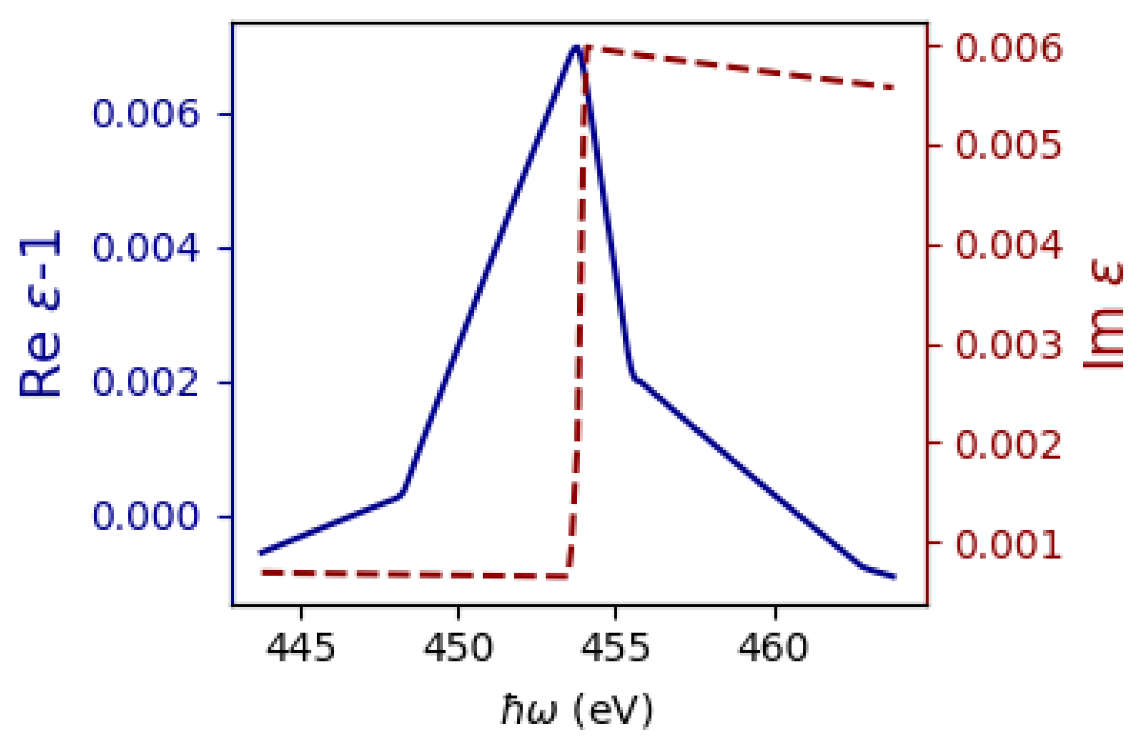
In the soft X-ray spectral range, ChR was certainly detected for target materials such as vanadium, titanium, beryllium, aluminum, and silicon [3,4,19,20], while for other materials, more detailed experimental studies are required. Therefore, in this study, we selected one of these materials to calculate the characteristics of hybrid radiation. Figure 2 shows the spectral dependencies of the real and imaginary components of the complex permittivity of titanium near the L absorption edge. From the presented dependencies, we can conclude that the Tamm–Frank criterion is satisfied in the considered energy range.
3. Numerical Results
3.1. Spectral and Angular Distributions of Hybrid Radiation
Considering the generation of radiation that occurs when the charged particle passes through an absorbing plate, we have to introduce terms such as a thin and thick targets. A thick target implies that the thickness of the plate, where the charge moves, is much larger than the TR coherence length in the target material for the direction of the polar angle θ, corresponding to the maximum value of the spectral-angular distribution of TR ( [21]). If the plate is so thin that its thickness is less than or equal to the TR coherence length, then we define such a target as thin. The TR coherence length was chosen as the target thickness criterion since the ChR coherence length in the target material tends to infinity [22]. Consequently, the ChR intensity is limited only by the absorbance of the target material. Since the TR coherence length is several times greater than the absorption length in the spectral region under consideration, we can state that in the case of a thin target, hybrid radiation can pass through the plate material without significant losses.
Let us first consider the simplest radiation geometry: normal incidence () of an electron on a titanium plate. Figure 3 shows the angular distributions in the plane and the spectral distributions of the emitted energy (integration is carried out over all observation angles and ) of the hybrid radiation. The main calculation parameters and explanations are provided in the caption of the Figure 3. As one can see from Figure 3, for a thin plate, the contribution of the ChR to the total intensity of hybrid radiation will depend on the electron path length in the radiator material (), which, in turn, is determined by both the target thickness and the electron incidence angle. Thus, in the case of a thin target, the spectral distribution of the emitted energy and the degree of monochromaticity of the hybrid radiation depend on the target thickness. Figure 3b shows the photon energy corresponding to the L3 absorption edge of titanium with a solid vertical line, revealing a sharp decline in the photon yield of high-energy hybrid radiation beyond the photoabsorption edge. The physical nature of this effect is simple. It lies in the fact that the ChR intensity decreases both as a result of a resonant increase in the photoabsorption of titanium, and a decrease in the value of the real part of the permittivity (see Figure 2).
Figure 4 illustrates the calculation results for the angular distributions in the plane and the spectral distributions of the emitted hybrid radiation energy for the case of a thick titanium plate for different values of the electron incidence angles. The dependences presented allow us to conclude that a change in the angle of incidence of a particle on a thick plate only results in a redistribution of the polarization radiation intensity in space and does not affect the total yield and spectral parameters of the hybrid radiation. This phenomenon is mainly attributed to the process of ChR photoabsorption in the target material, since the length of the charge particle path in the plate, which contributes to the ChR intensity, is limited by the absorbing abilities of the target material.
3.2. Spectral Distribution of Transition Radiation
In recent years, there has been a tendency to use the plasma equation to determine the dielectric properties of a substance in the soft X-ray spectral range. However, inaccurate use of the plasma model leads to the loss of the contribution of the anomalous dispersion of matter caused by the absorption edges. For this reason, it is customary to assume that TR in the considered spectral region has a polychromatic spectrum. Since TR parameters are determined by the optical properties of the medium, we can expect a resonant behavior of the spectral distribution of the emitted TR energy near the photoabsorption edges. In 1965, I.M. Frank, in a review article devoted to TR [23], proposed the idea of determining the optical parameters of a substance from measurements of the TR intensity and spectrum. Therefore, it would be reasonable to consider the spectral distribution of the emitted TR energy in the region of the photoabsorption edges of the target material and to estimate the contribution of the TR to the spectral distribution of the emitted energy of the hybrid radiation. Obviously, for the radiation geometry shown in Figure 1, there are two ways to eliminate the influence of ChR on the characteristics of the TR. First, let us consider another similar issue—we calculate the spectral distribution of the emitted TR energy for the backward TR (BTR). In order to determine the intensity of the magnetic field of the BTR, it is necessary to invert the sign of in expressions (1) and (2). Thus, we can use the developed model to determine the properties of the BTR. Secondly, we will use the Tamm–Frank criterion, which provides certain conditions on the occurrence of the Cherenkov effect, and calculate the radiation characteristics for the spectral range near the absorption edge, where the real part of the permittivity is less than unit.
Continuing with the consideration of a titanium plate in the energy region of the L3 edge of titanium photoabsorption, where the Tamm–Frank criterion is satisfied, let us, for simplicity, consider the geometry of the normal incidence of an electron on a target and analyze the impact of the target thickness on the spectral distribution of the emitted BTR energy. The spectral distributions of emitted BTR energy for titanium targets with different thicknesses are presented in Figure 5. The calculation results indicate that the maximum photon yield of BTR is observed for energy corresponding to the photoabsorption edge of the L3 shell of titanium and does not depend on the thickness of the plate. The impact of the target thickness on the spectral distribution of the emitted BTR energy is in periodic modulation. This modulation is significant only for thin plates since it is due to the effect of interference of TR fields. Figure 6 shows the spectral dependences of the real and imaginary components of the complex permittivity of titanium near the K absorption edge. The blue solid curve represents the spectral dependence of the real component of the complex permittivity. The figure shows that the maximum value of the real component is less than unity and, therefore, the Cherenkov effect will not appear near the K absorption edge of titanium.
Let us now turn to the analysis of the spectral distribution of the emitted TR energy in the forward direction and BTR in the spectral region near the K absorption edge of titanium. The calculation results presented in Figure 7 clearly show that the behavior of the intensities is the same for both types of radiation and has a resonant dip, the minimum of which corresponds to the photoabsorption energy of the titanium K1 shell. However, it should be noted that the intensity of the BTR is six orders less than for the TR in the forward direction.
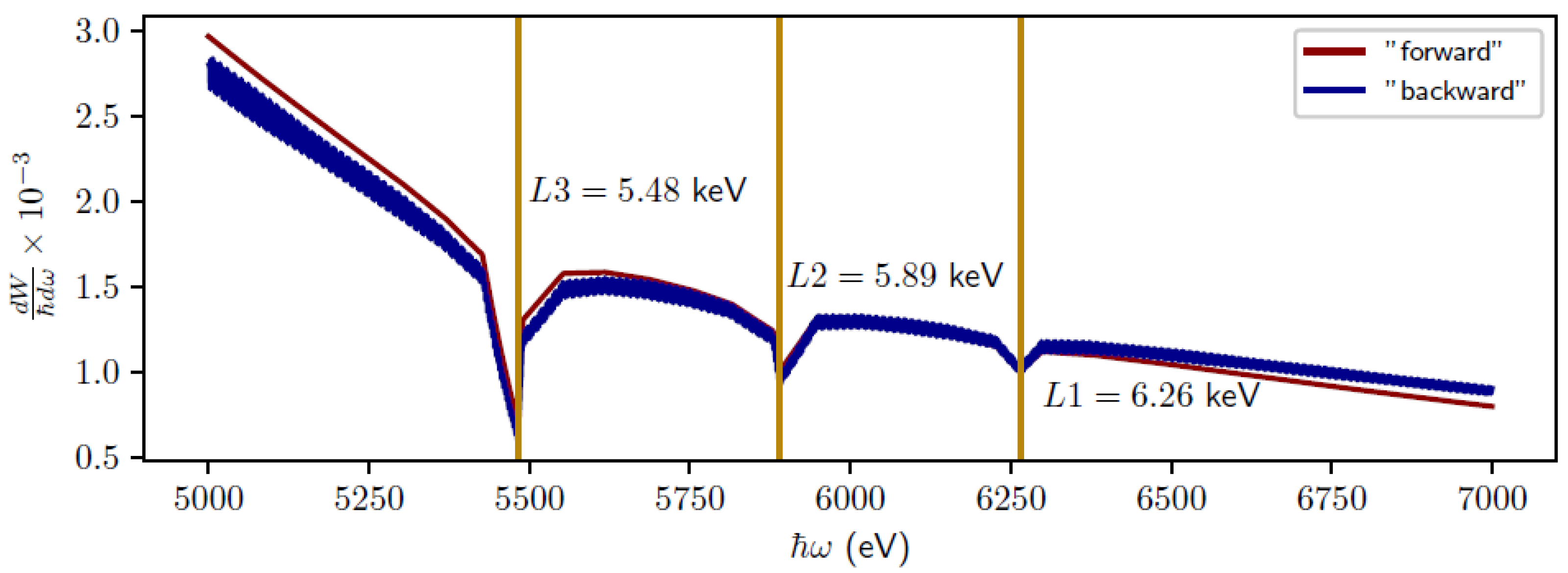
To further demonstrate the result obtained, let us consider the spectral distribution of the emitted TR energy from another target material. We chose lanthanum as the plate material. In the 5–7 keV spectral range, lanthanum has three photoabsorption edges for which the Tamm–Frank criterion is not met (see Figure 8). Figure 9 shows the spectral distributions of the emitted TR energy in the forward direction and BTR from the lanthanum target. It follows from the dependences presented that the spectral distributions of the emitted TR energy have sharp dips near the photoabsorption edges. The intensity minima of the TR spectral distribution correspond to the photoabsorption energies of the L3, L2, and L1 shells of lanthanum.
4. Conclusions
In this study, the following important results were obtained. We have demonstrated that changing the angle of incidence of a particle on a thick plate only leads to a redistribution of the intensity of polarization radiation in space and does not affect the total yield and spectral characteristics of both hybrid radiation and TR. The physical meaning of the result is that the effective length of the charge path in the screen, which contributes to the ChR intensity, is limited by the process of radiation absorption in the target material and is independent on the angle of incidence of a charge on the target.
However, in the case of a thin plate, the incidence angle will determine the effective path of the charge in the material of the plate. Therefore, an increase in the total yield and the degree of monochromaticity of the hybrid radiation can be achieved due to an increase in the ChR intensity and the contribution of the interference effects of the TR fields. Several important remarks should be made here. First, the ratio of the target thickness to the TR coherence length in the plate material will always be greater than unity for thick targets, while in the thin plates, this ratio will certainly be less or, in extreme cases, equal to unity. Thus, the highest yield of hybrid radiation photons will occur from the thick targets. Secondly, when dealing with the sliding angles of charge incidence on the plate, it is necessary to take into account the Fresnel coefficients, since for this geometry, the condition of internal reflection of the ChR from the target surface is satisfied.
The results of this study demonstrate that the spectral characteristics of TR from the plate, both for the forward and backward directions, in the spectral range near the photoabsorption edges of the K, L, and M shells of the radiator material, depend on the dielectric properties of the target and have resonant behavior.
Author Contributions
Conceptualization, M.V.S., B.A.A. and A.S.K.; methodology, A.S.K.; investigation, M.V.S. and B.A.A.; writing—original draft preparation, M.V.S. and Y.M.C.; writing—review and editing, A.S.K., S.R.U. and Y.M.C.; visualization, B.A.A.; project administration, S.R.U.; funding acquisition, S.R.U. All authors have read and agreed to the published version of the manuscript.
Funding
This study was supported by the Russian Science Foundation, project No. 23-22-00187.
Data Availability Statement
The original contributions presented in the study are included in the article, further inquiries can be directed to the corresponding authors.
Conflicts of Interest
Author A. S. Konkov was employed by the company The Joint Stock Company State Research Center of the Russian Troitsk. The remaining authors declare that the research was conducted in the absence of any commercial or financial relationships that could be construed as a potential conflict of interest.
References
- Anil, A.G.; Swaraj, S.; Subramanian, S.; Ramamurthy, P.C. Analysis of Cr(VI) bioremediation by Citrobacter freundii using synchrotron soft X-ray scanning transmission X-ray microscopy. Quantum Beam Sci. 2021, 5, 28. [Google Scholar] [CrossRef]
- Hayakawa, Y.; Takahashi, Y.; Kuwada, T.; Sakae, T.; Tanaka, T.; Nakao, K.; Nogami, K.; Inagaki, M.; Hayakawa, K.; Sato, I. X-ray imaging using a tunable coherent X-ray source based on parametric X-ray radiation. J. Instrum. 2012, 8, C08001. [Google Scholar] [CrossRef]
- Knulst, W.; van der Wiel, M.J.; Luiten, O.J.; Verhoeven, J. High-brightness, narrowband, and compact soft X-ray Cherenkov sources in the water window. Appl. Phys. Lett. 2003, 83, 4050. [Google Scholar] [CrossRef]
- Knulst, W. Cherenkov Radiation in the Soft X-ray Region: Towards a Compact Narrowband Source. Ph.D. Thesis, Technical Iniversity, Eindhoven, The Netherlands, 2004. [Google Scholar]
- Uglov, S.R.; Kaplin, V.V.; Kubankin, A.S.; André, J.-M.; Le Guen, K.; Jonnard, P.; de Rossi, S.; Meltchakov, E.; Delmotte, F. Cr/Sc multilayer radiator for oarametric EUV radiation in “water-window” spectral range. J. Phys. Conf. Ser. 2016, 732, 012017. [Google Scholar] [CrossRef]
- Hemberg, O. A Compact High-Brightness Liquid-Metal-Jet X-ray Source. Ph.D. Thesis, Royal Institute of Technology, Stockholm, Sweden, 2004. [Google Scholar]
- Andersen, J.U.; Bonderup, E.; Pantell, R.H. Channeling Radiation. Ann. Rev. Nucl. Part. Sci. 1983, 33, 453–504. [Google Scholar] [CrossRef]
- Baryshevsky, V.; Feranchuk, I.; Ulyanenkov, A. Parametic X-Ray Radiation in Crystals: Theory, Experiment and Applications; Springer: Berlin/Heidelberg, Germany, 2005. [Google Scholar]
- Tamm, I.E.; Frank, I.M. Coherent Radiation of Fast Electrons in a Medium. Doklady Akad. Nauk SSSR 1937, 14, 107–112. [Google Scholar]
- Frank, I.M. Transition radiation and the Cherenkov effect. Sov. Phys. Usp. 1962, 5, 740–746. [Google Scholar] [CrossRef]
- Zrelov, V.P.; Ruzicka, J. Hybrid radiation and its properties IV. Nucl. Instrum. Methods 1979, 160, 327–336. [Google Scholar] [CrossRef]
- Shevelev, M.; Konkov, A.; Alekseev, B. Spectral and polarization characteristics of X-ray hybrid radiation. Nucl. Instrum. Methods Phys. Res. B Beam Interact. Matter At. 2020, 464, 117–122. [Google Scholar] [CrossRef]
- Karlovets, D.V. On the theory of polarization radiation in media with sharp boundaries. J. Exp. Theor. Phys. 2011, 113, 27–45. [Google Scholar] [CrossRef]
- Shevelev, M.V.; Konkov, A.S. Pecularities of the generation of Vavilov-Cherenkov radiation induced by a charged particle moving past a dielectric target. J. Exp. Theor. Phys. 2014, 118, 501–511. [Google Scholar] [CrossRef]
- Shevelev, M.; Konkov, A.; Aryshev, A. Soft-x-ray Cherenkov radiation generated by a charged particle moving near a finite-size screen. Phys. Rev. A 2015, 92, 053851. [Google Scholar] [CrossRef]
- Sergeeva, D.Y.; Potylitsyn, A.P.; Tishchenko, A.A.; Strikhanov, M.N. Smith-Purcell radiation from periodic beams. Opt. Express 2017, 25, 26310–26328. [Google Scholar] [CrossRef] [PubMed]
- Landau, L.D.; Lifshitz, E.M. Electrodynamics of Continuous Media. In Course of Theoretical Physics; Butterworth-Heinemann: Oxford, UK, 1984; Volume 8. [Google Scholar]
- Henke, B.L.; Gullikson, E.M.; Davis, J.C. X-ray Interactions: Photoabsorption, Scattering, Transmission, and Reflection at E = 50–30,000 eV, Z = 1–92. At. Data Nucl. Data Tables 1993, 54, 181–342. [Google Scholar] [CrossRef]
- Uglov, S.R.; Vukolov, A.V. Observation of soft X-ray Cherenkov radiation in Be and Si foils. J. Instrum. 2021, 16, P07043. [Google Scholar] [CrossRef]
- Uglov, S.; Vukolov, A.; Kaplin, V.; Sukhikh, L.; Karataev, P. Observation of soft X-ray Cherenkov radiation in Al. EPL 2017, 118, 34002. [Google Scholar] [CrossRef]
- Ginzburg, V.I.; Tsytovich, V.N. Transition Radiation and Transition Scattering; A. Hilger: Bristol, UK; New York, NY, USA, 1990. [Google Scholar]
- Pafomov, V.E. Emission of a charged particle in the presence of an interface. Trudy FIAN 1969, 44, 28. (In Russian) [Google Scholar]
- Frank, I.M. Transition radiation and optical properties of matter. Sov. Phys. Usp. 1966, 8, 729–742. [Google Scholar] [CrossRef]
Figure 1.
Layout of the radiation geometry for a charged particle passing through an infinite plate of thickness d.
Figure 1.
Layout of the radiation geometry for a charged particle passing through an infinite plate of thickness d.
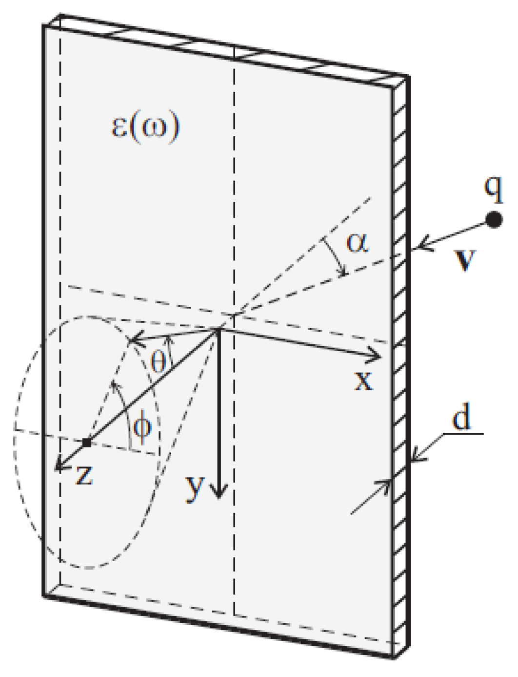
Figure 2.
Spectral dependences of the components of the complex permittivity of titanium near the L absorption edge. The real part of the complex permittivity is shown as a solid blue line; the imaginary part is shown as a dotted red line.
Figure 2.
Spectral dependences of the components of the complex permittivity of titanium near the L absorption edge. The real part of the complex permittivity is shown as a solid blue line; the imaginary part is shown as a dotted red line.

Figure 3.
Angular (a) and spectral (b) distributions of the emitted energy of hybrid radiation for different target thicknesses. Calculation parameters: target material—titanium, electron energy . The solid red line shows the angular and spectral distributions of the emitted energy of hybrid radiation from titanium foil with a thickness = 8 µm, the dotted blue line— = 0.8 µm, the dash-dotted green line— = 0.4 µm. The vertical line corresponds to the photon energy of the L3 absorption edge of titanium. For the calculation of the angular distribution of hybrid radiation for the case and for negative values of the polar angle , Equation (3) is averaged over the photon energy 443.8 − 463.8 eV, corresponding to the energy region near the L-edge of photoabsorption titanium.

Figure 4.
Angular (a) and spectral (b) distributions of the emitted energy of hybrid radiation for the case of a thick titanium plate at different values of the angle of incidence of an electron on the target. Calculation parameters: target material—titanium, = 8 µm, electron energy . The solid red line corresponds to the angle of incidence , the dotted blue line—, the dash-dotted green line—. The vertical line denotes the photon energy of the L3 absorption edge of titanium.

Figure 5.
Spectral distributions of the emitted BTR energy. Calculation parameters: target material—titanium, electron energy . The solid red line shows the spectral distribution of the emitted BTR energy from titanium foil with a thickness = 8 µm, the dotted blue line— = 0.8 µm, and the dash-dotted green line— = 0.4 µm. The vertical solid yellow line corresponds to the photon energy of the L3 absorption edge of titanium.

Figure 6.
Spectral dependences of the components of the complex permittivity of titanium near the K absorption edge. The real part of the complex permittivity is shown as a solid blue line; the imaginary part is shown as a dotted red line.
Figure 6.
Spectral dependences of the components of the complex permittivity of titanium near the K absorption edge. The real part of the complex permittivity is shown as a solid blue line; the imaginary part is shown as a dotted red line.

Figure 7.
Spectral distribution of the emitted TR energy. Calculation parameters: target material—titanium, = 8 μm, electron energy . The solid red line shows the spectral distribution of the emitted TR energy in the forward direction; the dotted blue line shows the BTR. The vertical solid yellow line corresponds to the photon energy of the K1 absorption edge of titanium. The spectral distribution of the emitted BTR energy is multiplied by a coefficient of 4.6·106 for the convenience of presenting the calculation results in one picture.

Figure 8.
Spectral dependences of the components of the complex permittivity of lanthanum near the L3, L2, and L1 absorption edges. The real part of the complex permittivity is shown as a solid blue line; the imaginary part is shown as a dotted red line.
Figure 8.
Spectral dependences of the components of the complex permittivity of lanthanum near the L3, L2, and L1 absorption edges. The real part of the complex permittivity is shown as a solid blue line; the imaginary part is shown as a dotted red line.

Figure 9.
Spectral distributions of the emitted TR energy. Calculation parameters: target material—lanthanum, = 8 μm, electron energy . The solid red line shows the spectral distribution of the emitted TR energy in the forward direction; the dotted blue line shows the BTR distribution. Vertical solid yellow lines correspond to the photon energy L3, L2, and L1 absorption edges of lanthanum. The spectral distribution of the emitted BTR energy is multiplied by a coefficient of 5·106 for the convenience of presenting the calculation results in one picture.


Table 1.
Parameters of X-ray sources based on the interaction of electron beam with solid target.
| Radiation Mechanism | , MeV | , keV | FWHM | Brilliance, Photon/(s·mm2·mrad2 ·0.1% FWHM) |
|---|---|---|---|---|
| ChR | 10–100 | 0.1–1 | 10−2–10−3 eV | ~109 |
| Channelling | 10–200 | 1–100 | 10% | ~106 |
| TR | 50–500 | 0.1–50 | 50% | ~109 |
| PXR | 10–500 | 1–50 | 1% | ~1012 |
Disclaimer/Publisher’s Note: The statements, opinions and data contained in all publications are solely those of the individual author(s) and contributor(s) and not of MDPI and/or the editor(s). MDPI and/or the editor(s) disclaim responsibility for any injury to people or property resulting from any ideas, methods, instructions or products referred to in the content. |
© 2024 by the authors. Licensee MDPI, Basel, Switzerland. This article is an open access article distributed under the terms and conditions of the Creative Commons Attribution (CC BY) license (https://creativecommons.org/licenses/by/4.0/).
Share and Cite
MDPI and ACS Style
Shevelev, M.V.; Konkov, A.S.; Uglov, S.R.; Alekseev, B.A.; Cherepennikov, Y.M. Spectral Characteristics of Polarization Radiation in the Water Window Range. Quantum Beam Sci. 2024, 8, 6. https://doi.org/10.3390/qubs8010006
AMA Style
Shevelev MV, Konkov AS, Uglov SR, Alekseev BA, Cherepennikov YM. Spectral Characteristics of Polarization Radiation in the Water Window Range. Quantum Beam Science. 2024; 8(1):6. https://doi.org/10.3390/qubs8010006
Chicago/Turabian StyleShevelev, M. V., A. S. Konkov, S. R. Uglov, B. A. Alekseev, and Yu. M. Cherepennikov. 2024. "Spectral Characteristics of Polarization Radiation in the Water Window Range" Quantum Beam Science 8, no. 1: 6. https://doi.org/10.3390/qubs8010006