Proceeding Paper

Experimental Validation of the Structural Integrity of Modular Horizontal Axis Wind Turbine Blades †

Department of Engineering and Mathematics, Sheffield Hallam University, Sheffield S1 1WB, UK
*
Author to whom correspondence should be addressed.
Presented at the Sustainable Places 2017 (SP2017) conference, Middlesbrough, UK, 28–30 June 2017.
Proceedings 2017, 1(7), 694; https://doi.org/10.3390/proceedings1070694
Published: 3 November 2017
(This article belongs to the Proceedings of the Sustainable Places 2017 (SP2017) Conference)

Abstract

:
The production, transportation and repair of long horizontal axis wind turbine blades measuring up to 85 m require expensive specialist machinery that increases the capital cost of wind power generation. A modular blade design is a potential solution to these problems however; the inclusion of joints could make the modular blades inherently weaker. This work investigates the effect of post-tensioned tendons on the structural integrity of modular blades, through cantilever deflection and tensile tests conducted on 3D printed small-scale prototypes. The experiment indicates 43% and 15.4% reduction in blade tip displacement and deflection caused by cyclic loading, respectively, in case of modular design with tendons compared to without tendons design.

1. Introduction

The long wind turbine blades measuring up to 85 m are constructed of a single piece of fibre-reinforced plastic in expensive specialised manufacturing machinery [1,2]. Moreover, transportation of these blades to the installation site is one of the major financial implication and placement barrier of wind turbines as expensive transportation means such as helicopters may be required [3,4]. A modular blade design can decrease the manufacturing and transportation cost since the blades can be constructed, transported, repaired or replaced in small sections, minimising the use of any specialised machinery [5,6]. The D78 modular wind turbine blade engineered by Blade Dynamics is the only segmented offshore-specific wind turbine and is currently in the testing phase [7]. The only commercial modular wind turbine blade is Gamesa’s G128 62.5 m blade, which features a central joint to reduce transportation costs [8]. Thirty metallic joints are bonded into the spar laminate and bolted together to aircraft industry standards for safety, heeding a 25% reduction in mass with no effect on aerodynamic efficiency. The joint increases design cost by approximately 10%, however, the financial savings offset this cost during transportation as each blade can be transported on two standard 27.4 m flatbed trucks.
Bhat et al. simulated resonant, static bending and fatigue tests in accordance with IEC61400-23 TS for a modular and comparative standard wind turbine blade using FEA [9]. The adhesive joint used in the modular design was modelled using cohesive zone modelling in ANSYS. They found the modular and standard blades heeded similar testing results, thus proving segmented blades are a viable alternative, especially when considering structural response, specifically in fatigue. The inclusion of joints makes the modular blades inherently weaker but can be toughened using post-tensioned tendons. Although the potential benefits of the modular blade design are well acknowledged, there is relatively little evidential knowledge on the performance of post-tensioned tendons in modular blade designs. This work aims to compare modular prototypes with a conventional design to find if this endeavour is structurally viable.

2. Materials and Methodology

2.1. Blade Prototype Design and Construction

Four wind turbine blade prototypes (single and modular design) 240–250 mm in length were designed in Computer Aided Design (CAD) software SolidWorks and 3D printed using Acrylonitrile-Butadiene-Styrene (ABS) material, see Figure 1. The ABS construction material was printed in layers of 0.245 mm parallel to the leading edge of the blade to replicate the layers of fibre-reinforced plastic (FRP) used to create actual blades. The modular design was fastened using M4 bolts and 1.6 mm steel cable inserted along through-holes in the outside wall of the prototypes to replicate the post-tensioned tendons. The cable was pulled taut and clamped at the opposite end to maintain tension.

2.2. Experimental Methods

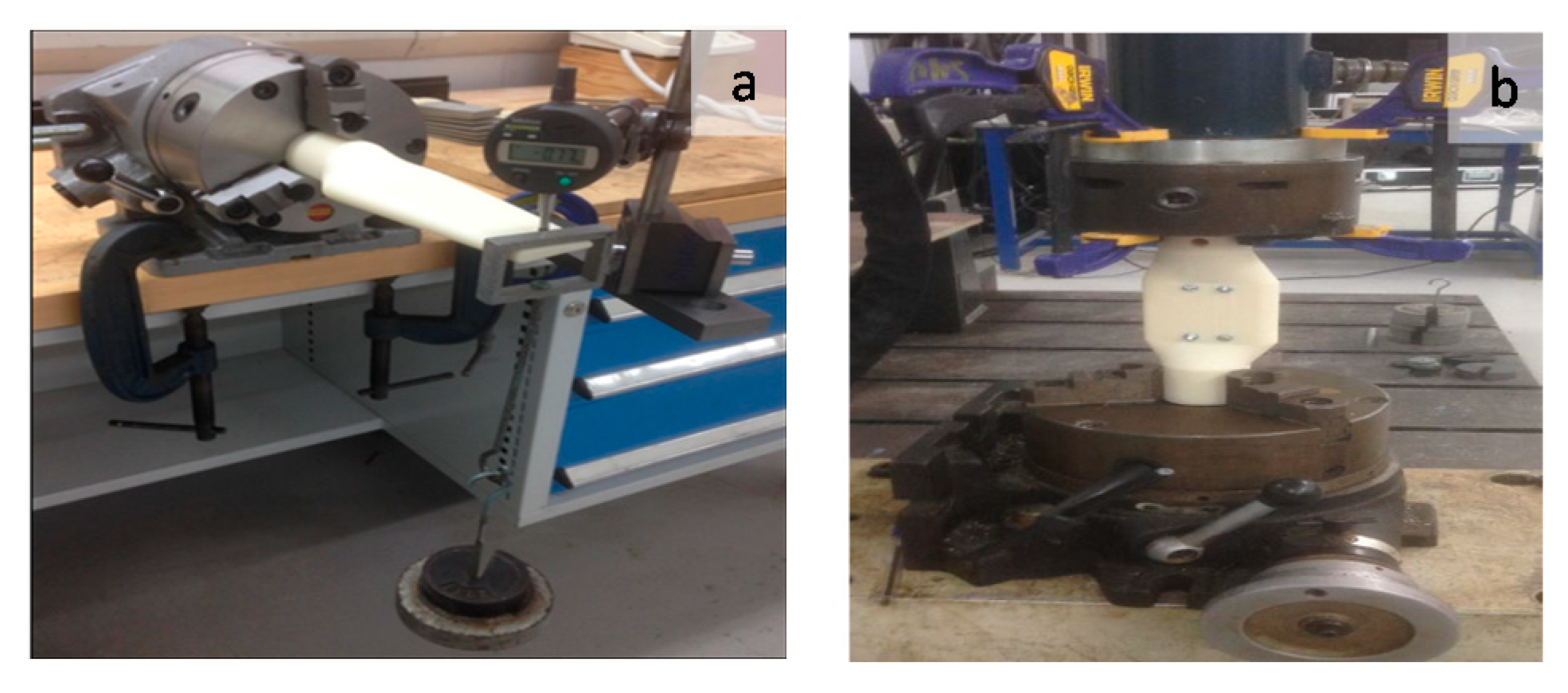
In this work, a number cantilever and tensile tests were carried out on the blade prototypes to determine their structural design integrity. The cantilevered beam deflection test, shown in Figure 2a, comprised the tapered aerofoil blade design clamped at one end horizontally and a force applied at the opposite end in a downwards direction. The test simulated the aerodynamic load applied to a wind turbine blade during service, as the blades root is fixed (replicating a hub attachment), and the load is applied at the end of the blade. Two loading cases were utilised for testing, with the blades loaded incrementally as well as cyclically, to closely replicate the changes in wind force caused by wind shear. The deflection was measured 10 mm from the end of the blade using a Mitutoyo 543–782 Absolute Digimatic Indicator in all of the cantilever tests. This testing approach was applied to a three-piece modular blade with and without tendons, and a single-piece hollow aerofoil blade to allow for comparison. The tensile extension test, shown in Figure 2b, comprised blade design with constant aerofoil section and large solid ends, clamping the blade at one end vertically and applying a force at the opposite end in a downwards direction.
A DMG servo-hydraulic mechanical 50 kN testing machine was used to produce the load required for significant deflection, with the prototype held in place using two dividing heads. The Rubicon Control Interface software extended each prototype in 0.1 mm increments whilst recording the peak load (kN) for each extension. The peak load was recorded for each 0.1 mm of extension until 4 mm. The central aerofoil shape was simplified and consistent in size throughout its length, as any inconsistency in size would result in the prototype failing at the weakest point, which may in turn affect the results. At the opposite end to the clamp, the 50 mm diameter solid cylinder, 40 mm in length, had a 10 mm mass hanger through-hole to allow mass to be hung from a steel rod passed through the blade. This end and adjoining transitional sections were solid to ensure failure would not occur and that the weakest part of the blade was the centre section, where the modular effect had the most influence.

3. Results and Discussion

3.1. Cantilever and Cyclic Loading Test
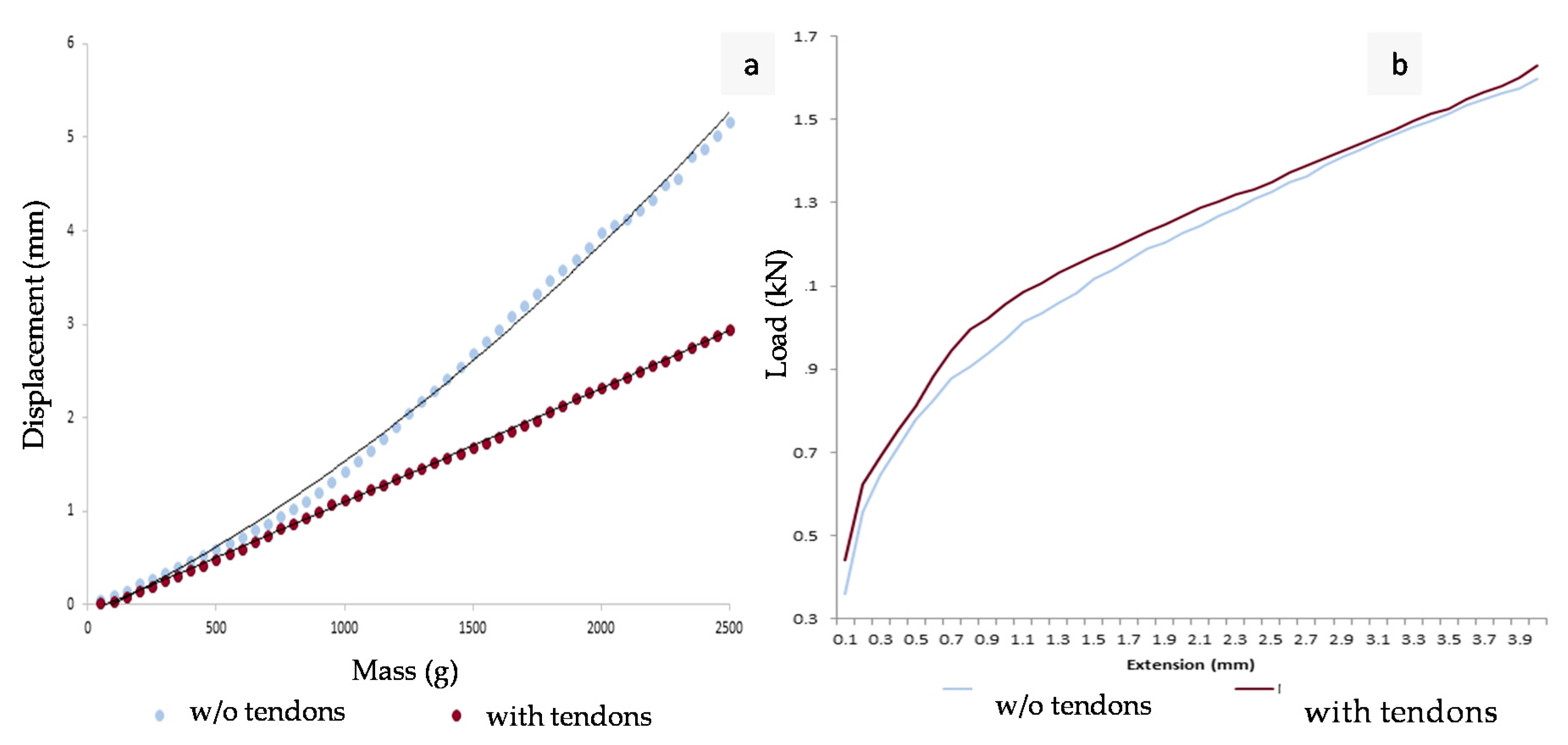
The addition of tendons reduced the displacement of the modular design by 43% in the incremental loading cantilever test, see Figure 3a. It also improved the modular assembly’s structural integrity as the tendons maintain a constant force perpendicular to the cantilevered load. The tensioning level of the tendons could be investigated as the use of multiple tendons or tendons with higher tension should decrease the effect of the inherent weakness using modules creates. The tendon design showed linear results compared to the modular design without tendons, which tended to have significant jumps in displacement most probably caused by the weaker joints. The addition of the tendons reduced these jumps by reinforcing the joints as intended.
The addition of tendons improved the modular performance by 15.4% during the cyclic loading tests. This is because the force applied by the tendons pulled the modules back into position when each load was removed. When evaluating the tendons performance in both cantilever tests, the improved lateral rigidity enhanced the designs resistance to the cantilevered load. When determining the tendons effectiveness, it was found as the mass increased the tendons reduced the displacement caused by cyclic loading. Hence, the tendons became more effective with higher loads during the cyclic testing; therefore, the tendons may have greater effect in large scale wind turbine applications. However, a modular system may be more suited to downwind horizontal axis turbines, as less blade stiffness is required in cantilevered loading. A limitation of the cantilever testing was the load was only applied at the end of the prototype instead of along the length of the aerofoil, therefore, did not replicate service conditions of a wind turbine blade completely accurately. This method was selected to ensure the load was applied as consistently to each prototype as possible and allowed the instrumentation to measure the deflection accurately.
Figure 3. (a) Comparison of the mean displacement values between the modular designs during the cantilever with incremental loading test. (b) Comparison of the mean displacement values between the modular designs during the tensile testing.
Proceedings 01 00694 g003

3.2. Tensile Tests

The addition of tendons improved the modular designs performance by 4% across all of the tensile tests, see Figure 3b. This is because the post-tensioned tendon prototype had force acting against the tensile load being applied; therefore, the tendons were resisting the modules being pulled apart. The application of tendons in larger scale blades could be a possibility to improve the tensile strength of a design. The differences which occurred at the beginning of the testing between the modular designs were most probably caused by the segments being drawn apart until this movement was limited by the M4 bolts. This was significantly reduced by the tendons as the modular sections were held together more affectively proceeding and during testing. One possible source of error during the testing was that the tendons were tensioned by hand, due to the small diameter of the cable. If greater tension was applied to the tendons before the testing, the modular design with tendons would most likely have performed even better.

4. Conclusion

The addition of post-tensioned tendons increased the structural rigidity of modular wind turbine blades significantly. Post-tensioned tendons may be the most effective method of joining modular wind turbine blades as the tendons are encased in a plastic sheath, therefore, less erosion of the FRP would take place compared with alternative metallic joining methods. Nevertheless, there are a few disadvantages of using modular wind turbine blades, as the designs will be heavier, require more onsite assembly and a slight increase in production costs. However, once the design has been refined to achieve similar or even improved performance compared to the standard single-piece design currently used, the reduction in transportation and maintenance costs should outweigh these negatives and aid in increasing the usage of large wind turbine systems worldwide.

Author Contributions

Abhishek Asthana and Sanjay Mukherjee conceived the concept of modular blades and developed the methodology for testing the structural integrity of the blades. Sara Mountney provided valuable insights into materials for making the blade and also did the literature review. Ryan Griffiths actually designed the blades and conducted the structural integrity tests. All co-authors contributed to writing the paper.

Conflicts of Interest

The authors declare no conflict of interest.

References

  1. Institute of Mechanical Engineers. Available online: www.imeche.org/news/news-article/giant-7mw-fife-offshore-turbine-completed (accessed on 1 February 2017).
  2. Manwell, J.F.; McGowan, J.G.; Rogers, A.L. Wind Energy Explained: Theory, Design and Application; John Wiley & Sons Ltd: Chechester, UK, 2009; Volume 1. [Google Scholar]
  3. Hau, E. Wind Turbines: Fundamentals, Technologies, Applications, Economics, 2nd ed.; Springer-Verlag: Heidelberg, Berlin, 2006. [Google Scholar]
  4. Power Monthly. Available online: www.windpowermonthly.com/article/1000918/cutting-transport-costs-down-size (accessed on 17 March 2017).
  5. Wind Power Engineering & Development. Available online: www.windpowerengineering.com/blades/longer-blades-coming-industry-transport-problems-says-consultant/ (accessed on 13 March 2017).
  6. Navigant Research. Available online: www.windpowerengineering.com/blades/longer-blades-coming-industry-transport-problems-says-consultant/ (accessed on 21 March 2017).
  7. Clean Technica. Available online: cleantechnica.com/2015/08/13/new-modular-blade-dynamics-wind-turbine-blade-begins-testing-blyth/ (accessed on 1 March 2017).
  8. Composites World. Available online: www.compositesworld.com/articles/modular-design-eases-big-wind-blade-build (accessed on 3 March 2017).
  9. Bhat, C.; Noronha, D.J.; Saldanha, F.A. Structural Performance Evaluation Of Modularized Wind Turbine Blade Through Finite Element Simulation. Int. J. Mech. Aerosp. Ind. Mechatron. Manuf. Eng. 2015, 9, 930–942. [Google Scholar]
Figure 1. 3D printed single-piece and modular ABS blade prototypes with (i) tapered aerofoil blade design and (ii) constant aerofoil section and large solid ends design.
Proceedings 01 00694 g001
Figure 2. (a) Cantilever test setup. (b) Tensile test setup.
Proceedings 01 00694 g002