Proceeding Paper

Position Measurement Based on Fisheye Imaging †

Shanxi Key Laboratory of Signal Capturing and Processing, North University of China, Taiyuan 030051, China
*
Author to whom correspondence should be addressed.
Presented at the 7th International Symposium on Sensor Science, Napoli, Italy, 9–11 May 2019.
Proceedings 2019, 15(1), 38; https://doi.org/10.3390/proceedings2019015038
Published: 15 August 2019
(This article belongs to the Proceedings of 7th International Symposium on Sensor Science)

Abstract

:
For the omnidirectional measurement, the collected images of large-angle fisheye lens need to be corrected and spliced before next procedure, which is complicated and inaccurate. In this paper, a direct position measurement method based on fisheye imaging is proposed for large-angle imaging without any image correcting and splicing. A nonlinear imaging system of fisheye lens is used to acquire the sequence images based on its distortion model, and the critical distortion features of the sequence images are extracted, which contains the position information. And a BP neural network is trained with the extracted image features of previous standard experimental dataset. Finally, the trained BP neural network is employed to measure the object’s distance. Experimental results demonstrate show that the proposed method achieves simple close-object distance measurement with high robustness and a measurement error of ±0.5cm. The proposed method overcomes the shortcomings of conventional measurement methods and expands the fisheye applications filed for omnidirectional measurement.

1. Introduction

With the increasing application of navigation systems, drones, machine vision, etc., especially for unmanned platforms, all-round target measurement technology is a significant demand. As the limited filed view of conventional visual, a scene with a large field of view often requires multiple images with several rotations to be taken, which cannot meet some specific applications [1]. The appearance of the fisheye lens overcomes the shortage of the traditional lens angle of view, and the angle of view can usually reach or exceed 180° [2]. It has become a new research direction and new field of modern computer vision research. The fisheye lens brings serious image distortion while bringing a super wide-angle view. If you want to use the perspective projection information of these distorted images, then you need to study a measurement method suitable for distorted images. Therefore, the research on measurement methods based on fisheye imaging is particularly important.
The existing omnidirectional target measurement technology mainly uses binocular omnidirectional measurement technology and image stitching using a single lens rotation to achieve panoramic target measurement. Y. T [3] invented a stereo vision measuring device for binocular omnidirectional vision sensors, which performed stereoscopic vision measurements; F. D [4] proposed a panoramic vision model and used a linear projection onto the image to obtain a projection model; J. W et al. [5], after obtaining the target point to be tested, compared with the azimuth position of the calibration to obtain the azimuth of the target, and the measurement error is within 2°. Z. Z et al. [6] proposed a panoramic image measurability method based on the spherical surface model fisheye distortion correction, the measurement error is within 10%. X. X [7] used the fisheye lens to measure the inner wall of the borehole. The image of the fisheye collected was first corrected and then expanded, and then the unfolded image was spliced into a large seamless image for measurement. However, the steps of the above method are too cumbersome and have certain limitations, and the correction error and the stitching error are added, so that the measurement error is increased.
In view of the shortcomings of the above measurement models, this paper proposes a method based on fisheye imaging position measurement. Since the features of the object are difficult to extract in the actual scene, a method of projecting light onto the object using the line structure is used to facilitate feature extraction. Using the characteristics of the fisheye image with different degrees of distortion at different imaging distances [8], spatially consecutive sequence distortion images are generated; the point features of the distorted images at different distances are used as input sets, and the corresponding distance is the output set. The BP neural network is trained to obtain a measurement model to achieve position measurement of the fisheye distortion image.

2. Theoretical Model and Image Acquisition System

2.1. Fisheye Lens Imaging Model

The fisheye lens is a special super wide-angle lens with a short focal length between 6 and 16 mm. Its biggest feature is that the field of view is very large and can approach or even equal to 180 degrees. As documented in [9], fisheye lenses are usually designed to obey one of the following projection models:
r = 2 f tan ( ω / 2 ) (   stereographic   projection )
r = f ω   ( equidistance   projection )
r = 2 f sin ( ω / 2 )   ( solid   angle   projection )
r = f sin ω   ( orthogonal   projection )
Here ω is the angle between the major axis and the incident ray, r is the distance between the image point and the main point, and f is the focal length. As shown in Figure 1a, we approximated the model with five different projections using the least squares method. The difference between the pinhole camera and the fisheye camera is shown in Figure 1b, the fisheye camera at point p is projected as point p and the pinhole camera projection is at P’.
From the point of view of automatic calibration, if there is an imaging model suitable for different types of lenses, it is very meaningful for our later research. Therefore, we need to consider the general form of the projection model:
r θ = k 1 θ + k 2 θ 3 + k 3 θ 5 + k 4 θ 7 + k 5 θ 9 +
where {k i }(i = 1, 2, 3, 4, 5) is the coefficient. Equation (5) contains only four parameters, which can approximate all projection models with higher precision.

2.2. Image Acquisition System

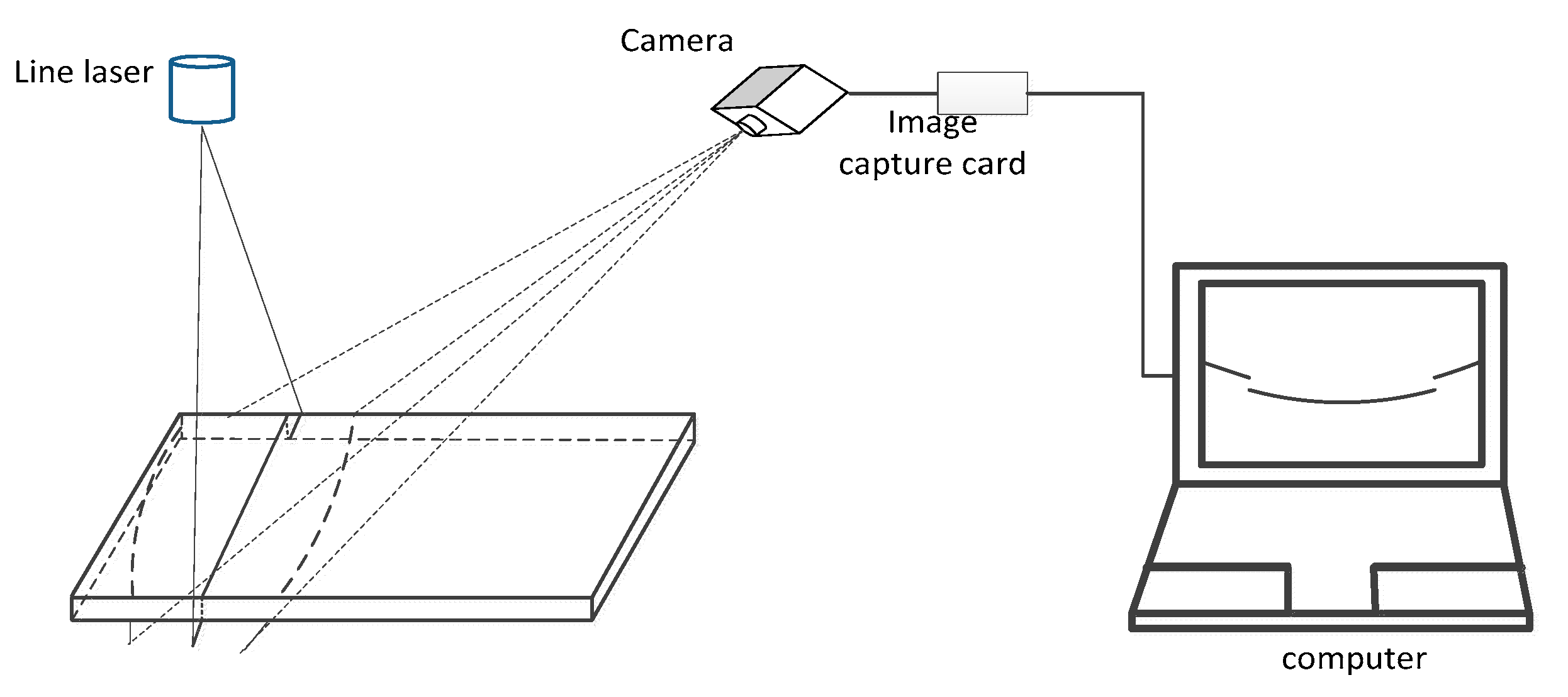
According to the fisheye imaging model, there are a lot of distortions in the fisheye image. The distortion is characterized in that except for the scene located at the center of the image, the scenes that are supposed to be vertical or horizontal are distorted, and the farther away from the center, The greater the degree of distortion. For the same part where the object is distorted, the farther the shooting distance is, the smaller the distortion occurs, and the closer the shooting distance is, the more distortion occurs. Figure 2 shows the fisheye image acquisition system.

3. Establish a Network Model

3.1. Building a Data Set

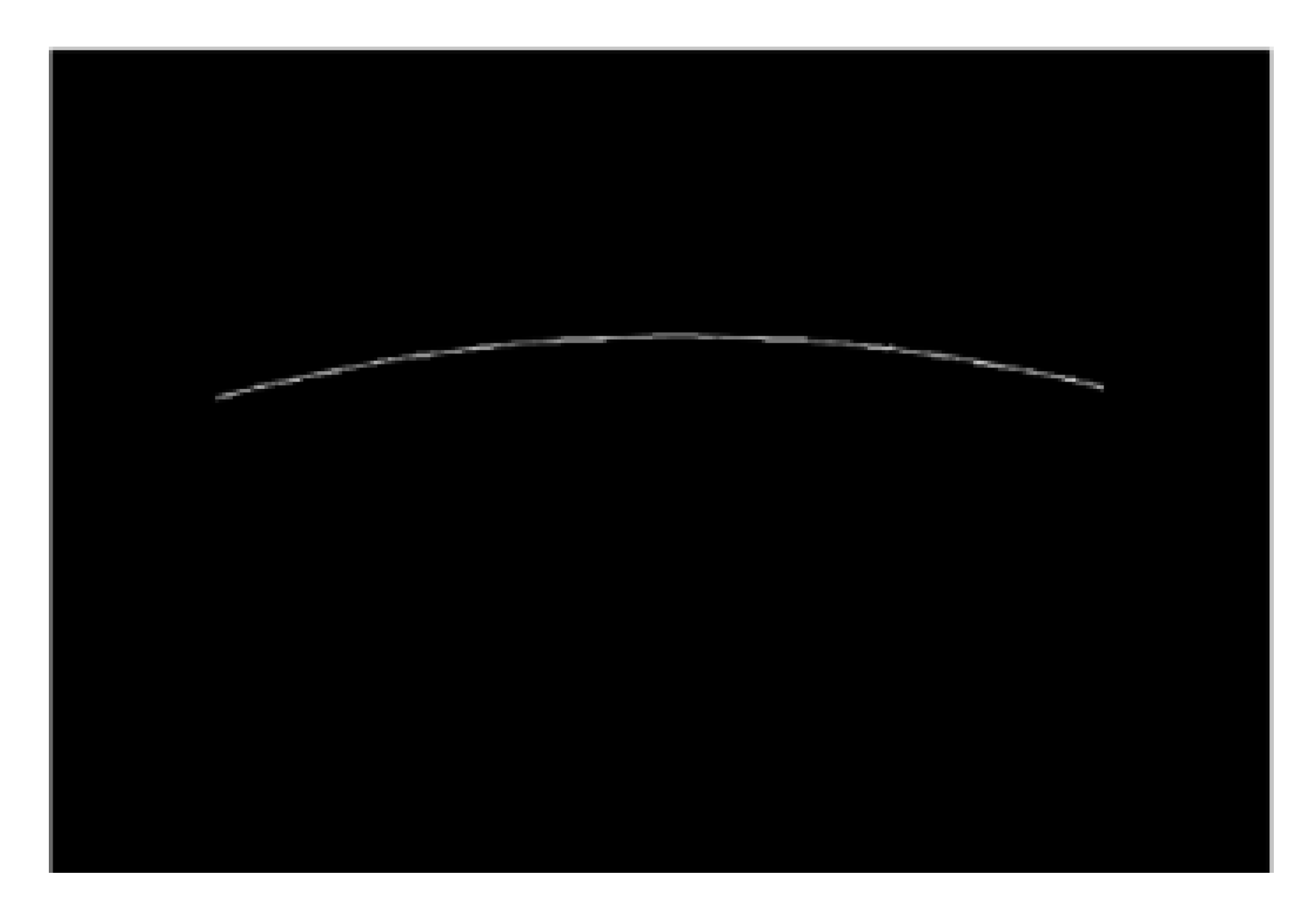
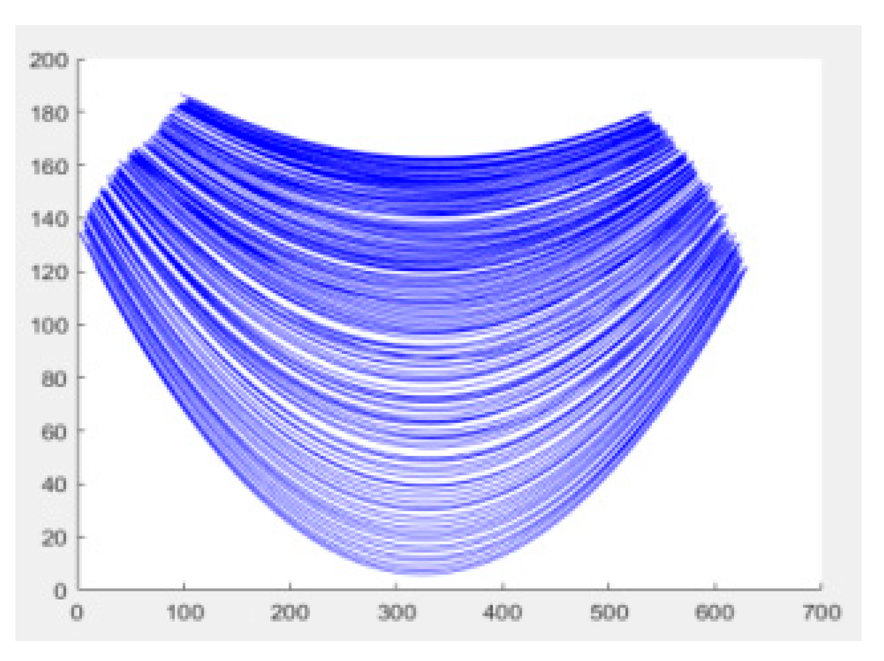
The experiment photographed a fisheye distortion sequence image of the object 30 cm to 2 m from the lens with an interval of 5 mm. The 10 point coordinates on the same position curve at different distances are extracted as data sets, as shown in Table 1. The 341 sets of images collected by the system were preprocessed. As shown in Figure 3, it is a set of structural light distortion images of the fisheye lens at a distance of 90 cm from the projection screen. As shown in Figure 4, the results of the fitting curve at a distance of 30cm to 110cm clearly show the difference in the degree of distortion of the structured light distortion image at different distances. The closer the object is to the lens, the greater the degree of deformation.

3.2. Establish a Network Model

The experiment was run in the MATLAB 2017b environment. 1) Extract the point coordinates of the fitting curve at all distances as the input set of the BP neural network; 2) Set the parameters to train the network; 3) Test the regression using the trained network.

4. Results and Discussions

As shown in Figure 5, the test set distance prediction results are compared (blue is the true value and red is the predicted value).
From the experimental results shown in Figure 5., it can be seen that the predicted output of the BP neural network is not much different from the actual output. When the object only performs horizontal sequence motion, the maximum error can be controlled at 5% using the method. The simplicity and feasibility of the method are proved. In the industry, camera calibration and various cumbersome processes can be eliminated, and production efficiency can be improved.

Author Contributions

Conceptualization, X.L. and Y.H.; methodology and implementation, K.L. and Y.C.; experiment and data processing, X.L. and Z.L.; draft writing, X.L.; draft review, Y.H.

Funding

The 15th Postgraduate Science and Technology Project of North University of China.

Acknowledgments

The authors would like to thanks the school of graduate at North University of China for their help in Funding.

Conflicts of Interest

The authors declare no conflict of interest or state.

References

  1. Chu, G. Research on Fisheye Binocular Vision Imaging and Positioning Technology. Master’s Thesis, Yan Shan University, Yanshan, China, 2016. [Google Scholar]
  2. Moreau, J.; Ambellouis, S.; Ruichek, Y. 3D reconstruction of urban environments based on fisheye stereovision. In Proceedings of the 2012 Eighth International Conference on Signal Image Technology and Internet Based Systems, Naples, Italy, 25–29 November 2012. [Google Scholar]
  3. Tang, Y.; Zong, M.; Jiang, J.; Chen, M.; Zhu, Y. Design of the same-directional binocular stereo omnidirectional sensor. J. Sens. Technol. 2010, 23, 791–798. [Google Scholar]
  4. Devernay, F.; Faugeras, O. Straight lines have to be straight. Mach. Vis. Appl. 2001, 13, 14–24. [Google Scholar] [CrossRef]
  5. Wu, J.; Yang, K.; Zhang, N. Analysis of target monitoring and measurement system based on fisheye lens. Opt. Technol. 2009, 35, 599–603. [Google Scholar]
  6. Zhan, Z.; Wang, X.; Peng, M. Research on key algorithms for panoramic image measurement of fisheye lens. Surv. Mapp. Bull. 2015, 1, 70–74. [Google Scholar]
  7. Xu, X. Research on Image Measuring System of Borehole Inner Wall. Master’s Thesis, Changchun University of Science and Technology, Changchun, China, 2011. [Google Scholar]
  8. Pan, H.; Wang, M.; Xu, J. Study on the Influence of Imaging Distance on Image Distortion Coefficient. J. Metrol. 2014, 3, 221–225. [Google Scholar]
  9. Kannala, J.; Brandt, S. A generic camera model and calibration method for conventional, wide-eye and fisheye lenses. IEEE Trans. Pattern Anal. Mach. Intell. 2006, 28, 1335–1340. [Google Scholar] [CrossRef]
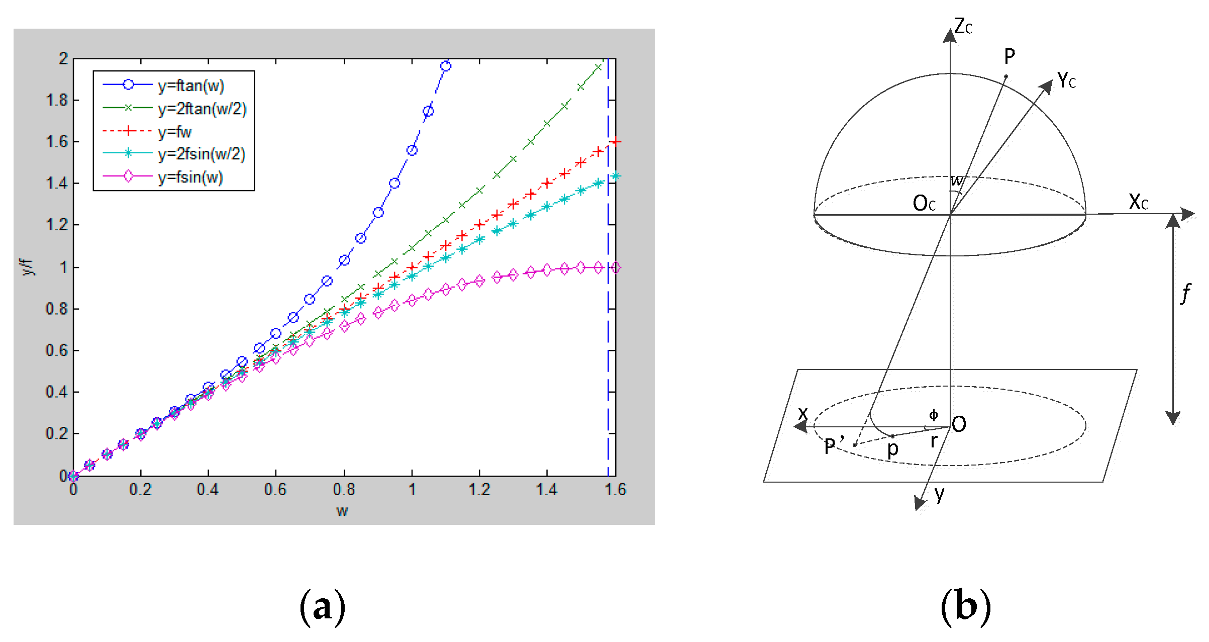
Figure 1. (a) Relationship between four imaging formulas and ideal imaging (b) Fisheye camera model true lens does not completely follow the projected projection model.
Proceedings 15 00038 g001
Figure 2. Image acquisition system of the fisheye.
Proceedings 15 00038 g002
Figure 3. Distortion image at 90cm.
Proceedings 15 00038 g003
Figure 4. Image distance of 30cm to 110cm.
Proceedings 15 00038 g004
Figure 5. The test set distance prediction results are compared.
Proceedings 15 00038 g005
Table 1. Data set of network.
No.Image Signal File 1Point 1Point 2Point 9Point10Distance(mm)
1Ima_300.jpg(36,78)(49,67)(143,57)(155,63)300
2Ima_305.jpg(35,77)(49,65)(143,56)(156,62)305
3Ima_310.jpg(34,76)(46,66)(142,53)(153,59)310
340Ima_1995.jpg(9,48)(21,37)(114,9)(127,11)1995
341Ima_2000.jpg(8,47)(20,37)(113,8)(127,9)2000
1 The file contains image of Linear structured light at different distances.