Power Flow Management in a Wind Generation System Using a Dual Feed Induction Generator †

 ,
, 
Abstract
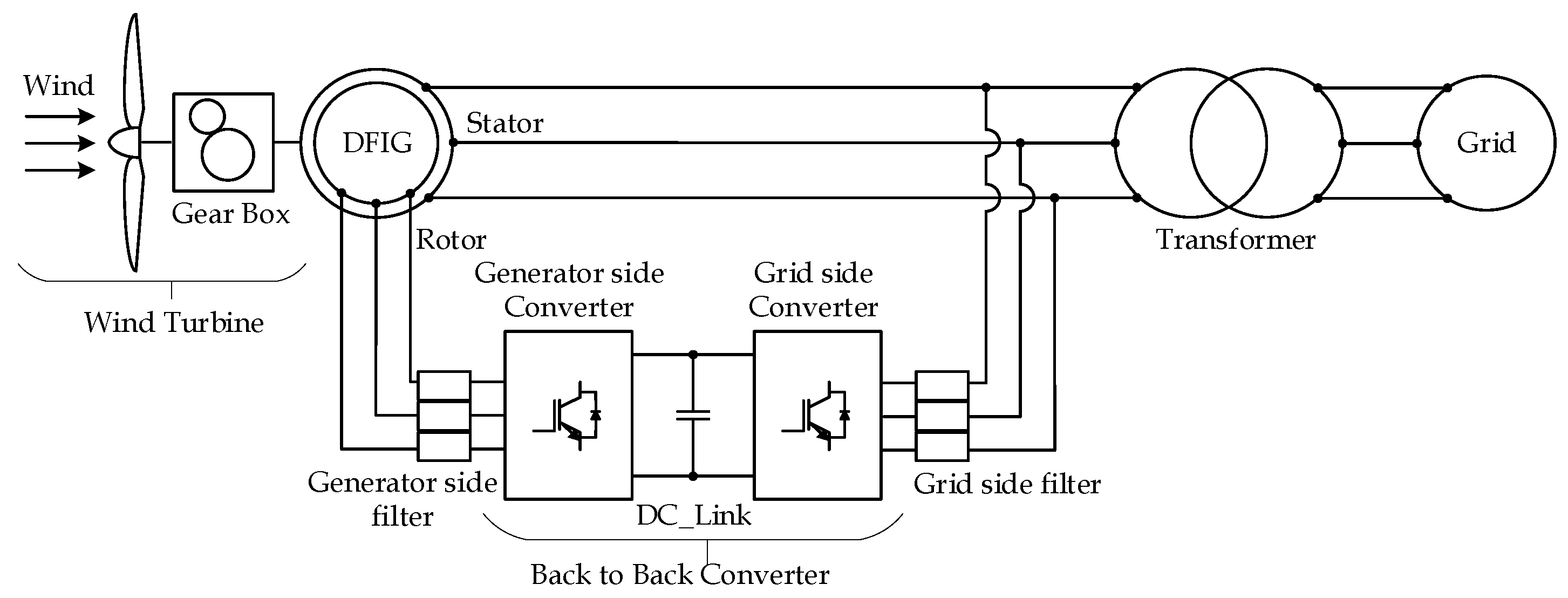
:1. Introduction
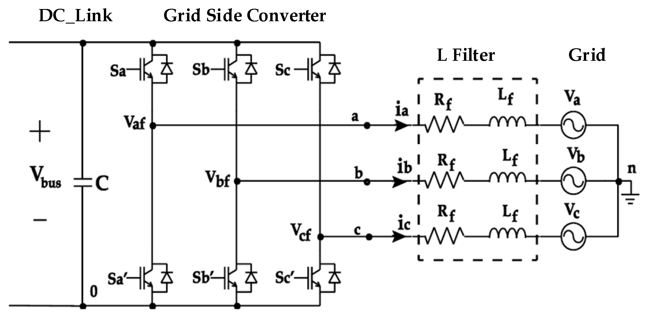
2. Grid Side Converter
3. Current Controller Design
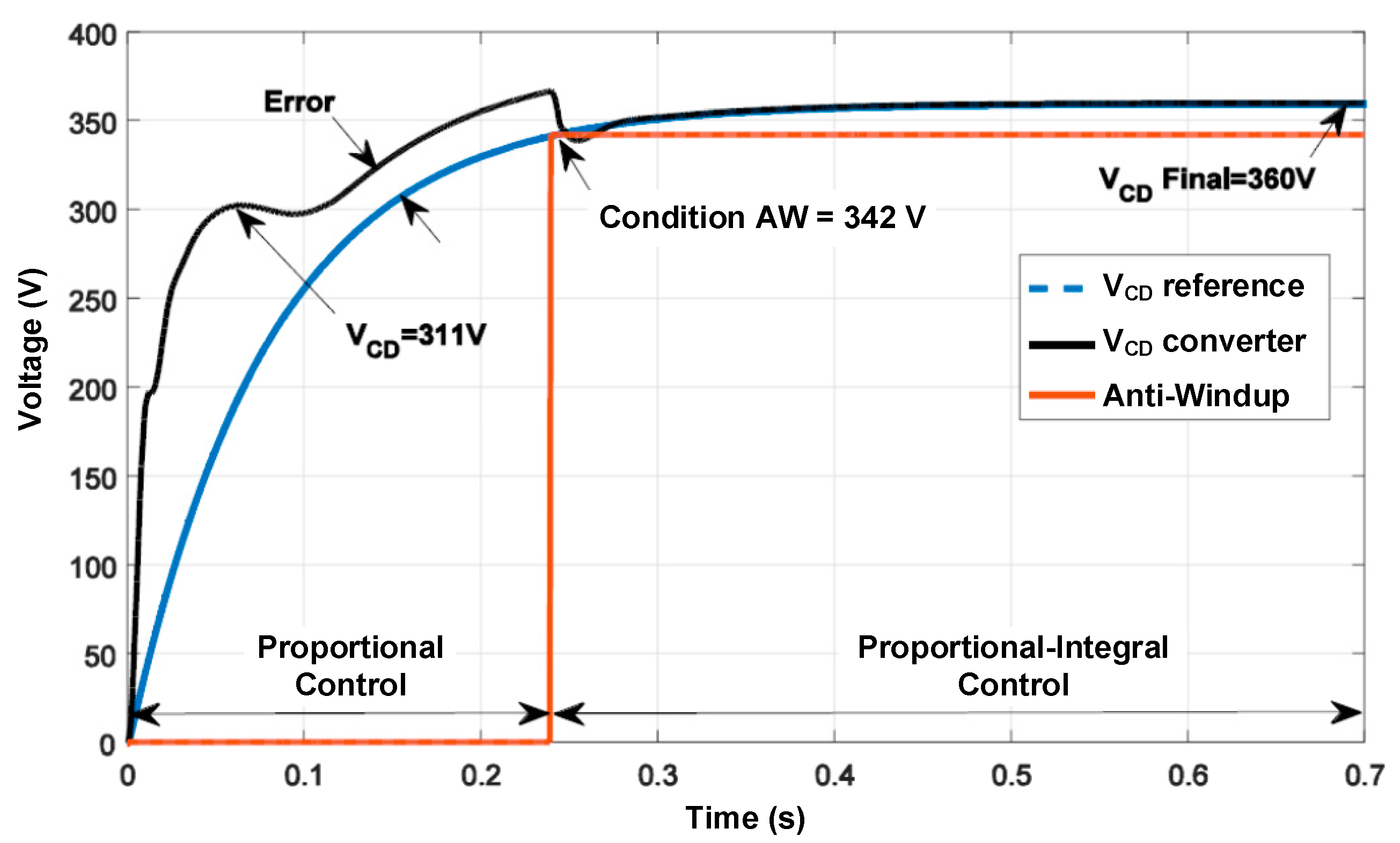
4. Voltage Controller Design
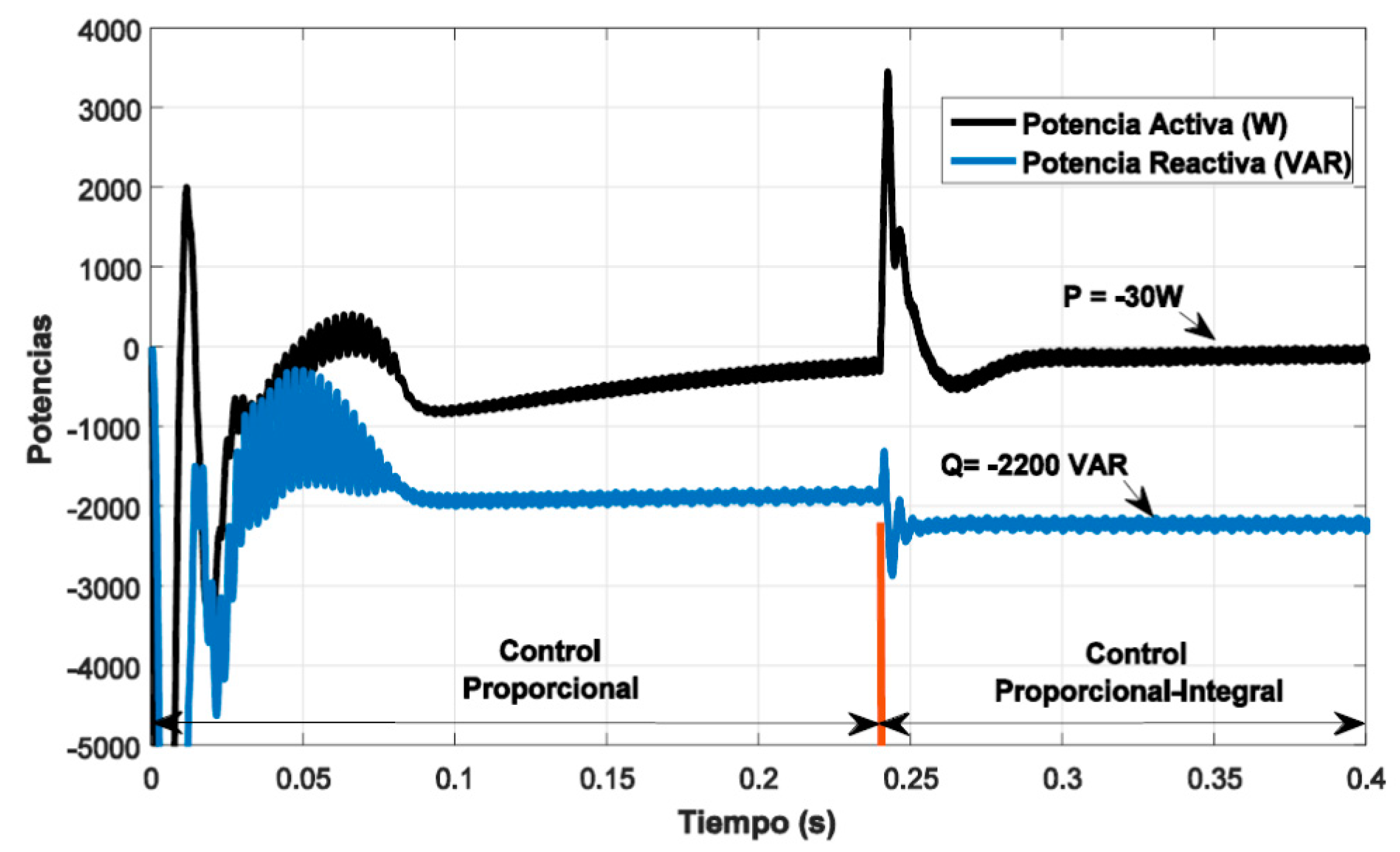
5. Results
6. Conclusions
References
- Hamdan, M.O.; Hejase, H.A.; Noura, H.M.; Fardoun, A.A. ICREGA’14-Renewable Energy: Generation and Aplications; Springer: Cham, Switzerland, 2014. [Google Scholar]
- Abad, G.; López, J.; Rodríguez, M.A.; Marroyo, L.; Iwanski, G. Doubly Fed Induction Machine, Modeling and Control for Wind Energy Generation; Wiley: Hoboken, NJ, USA, 2011. [Google Scholar]
- Bose, B. Modern Power Electronics and AC Drivers; Prentice Hall: Upper Saddle River, NJ, USA, 2002. [Google Scholar]
- Garcerá, G.; Figueres, E.; Abellán, A. Conversores conmutados: Circuitos de Potencia y Control; Servicio de Publicaciones: Valencia, Spain, 1998. [Google Scholar]
- Seok, J.K.; Kim, K.T.; Lee, C.D. Automatic Mode Switching of P/PI Speed Control for Industry Servo Drives Using Online Spectrum Analysis of Torque Command. Industrial Electronics. IEEE Trans. 2007, 54, 2642–2647. [Google Scholar]

Publisher’s Note: MDPI stays neutral with regard to jurisdictional claims in published maps and institutional affiliations. |
© 2018 by the authors. Licensee MDPI, Basel, Switzerland. This article is an open access article distributed under the terms and conditions of the Creative Commons Attribution (CC BY) license (https://creativecommons.org/licenses/by/4.0/).
Share and Cite
Tenorio, P.H.; Rivas, J.J.R.; Castillo, O.C.; González, R.O.; Aguilar, J.V.C. Power Flow Management in a Wind Generation System Using a Dual Feed Induction Generator. Proceedings 2018, 2, 1269. https://doi.org/10.3390/proceedings2201269
Tenorio PH, Rivas JJR, Castillo OC, González RO, Aguilar JVC. Power Flow Management in a Wind Generation System Using a Dual Feed Induction Generator. Proceedings. 2018; 2(20):1269. https://doi.org/10.3390/proceedings2201269
Chicago/Turabian StyleTenorio, Pedro Hernández, Jaime José Rodríguez Rivas, Oscar Carranza Castillo, Rubén Ortega González, and José Victoriano Chávez Aguilar. 2018. "Power Flow Management in a Wind Generation System Using a Dual Feed Induction Generator" Proceedings 2, no. 20: 1269. https://doi.org/10.3390/proceedings2201269