Experimental Model Validation and Fatigue Behaviour of Cold-Formed High Strength Steel †


Abstract
:1. Introduction
2. Experimental Procedure
2.1. Materials and Specimen
2.2. Measurement Technique
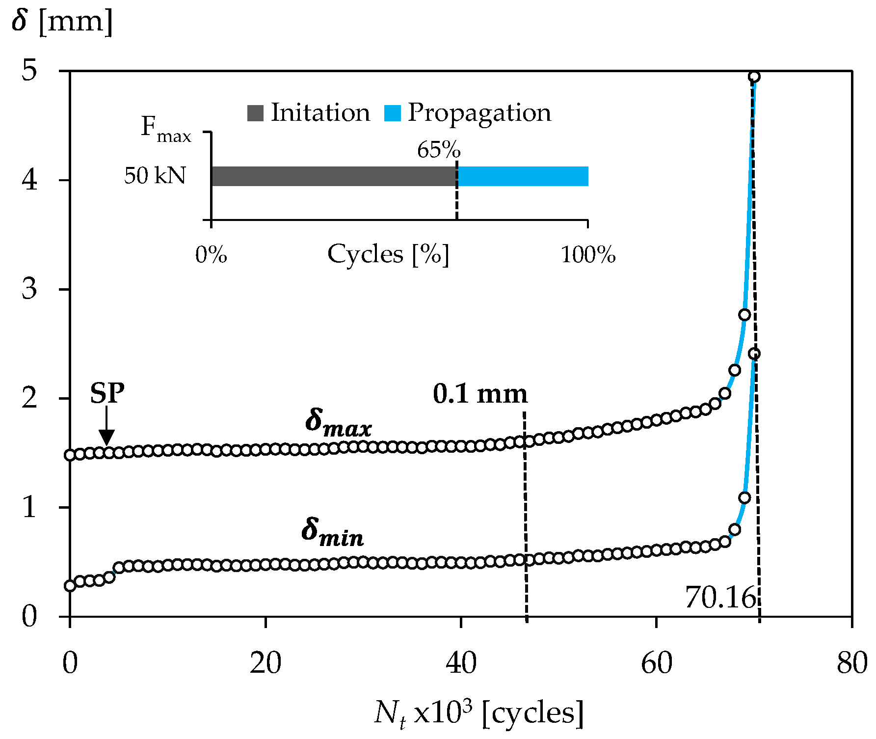
2.3. V-Fatigue Test
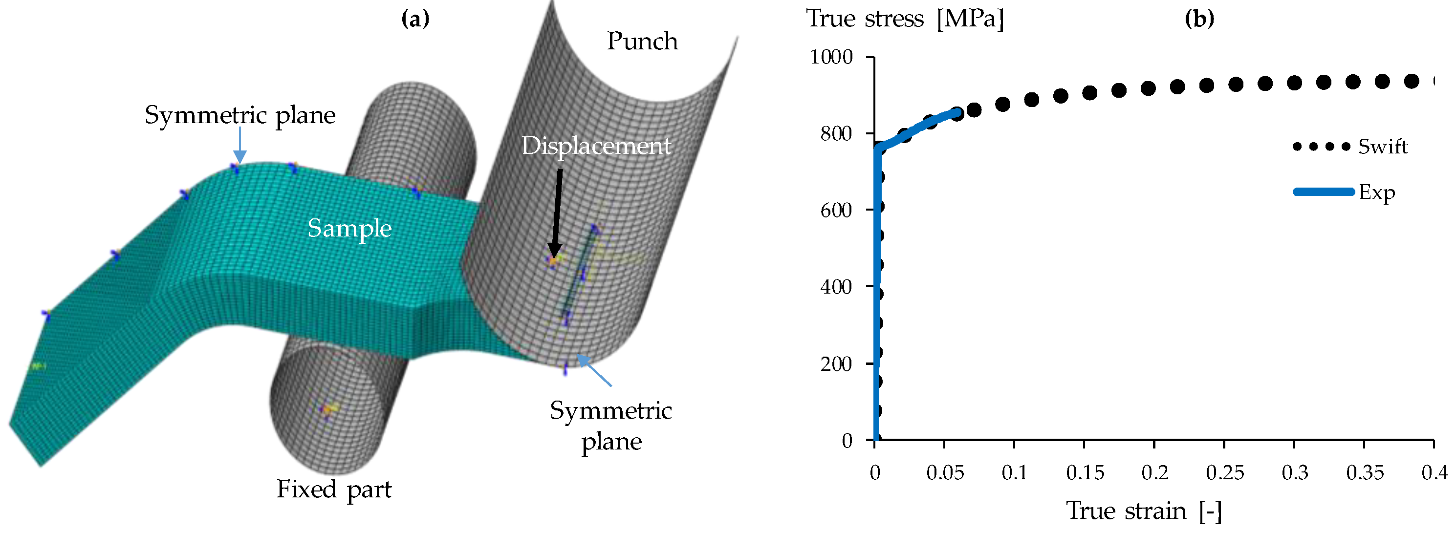
3. FE-Modelling
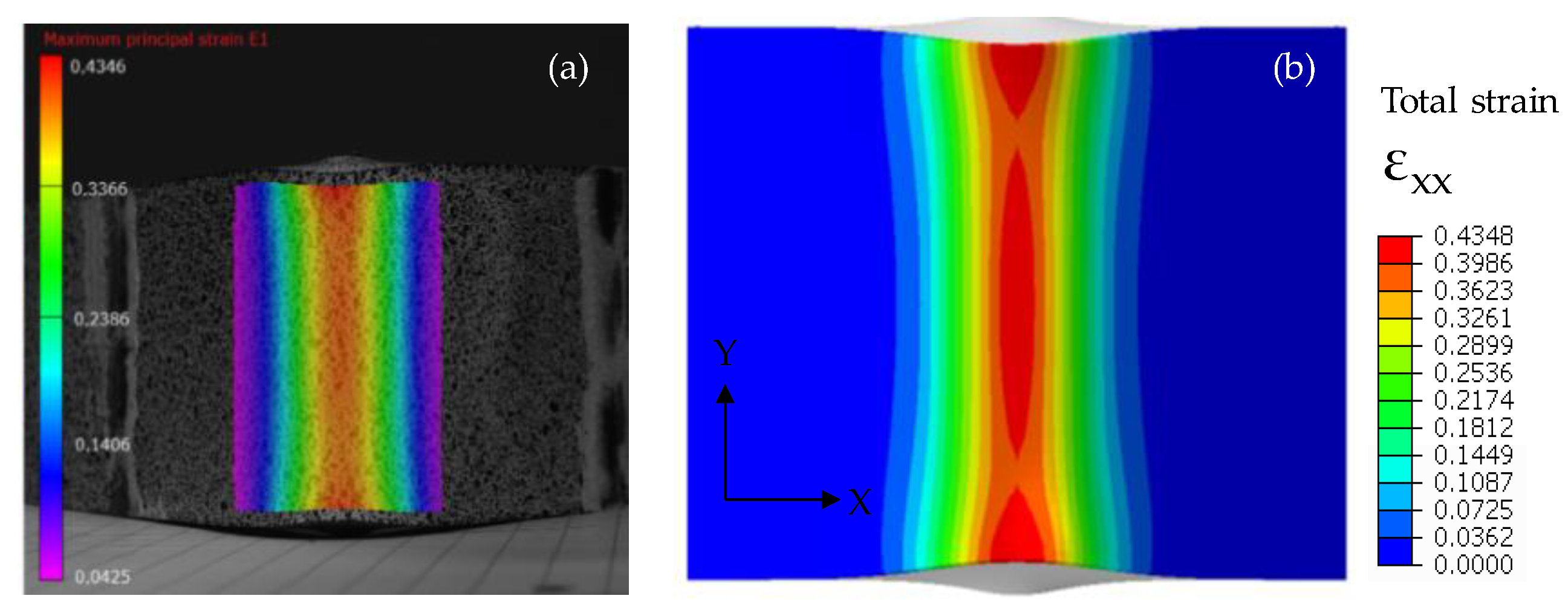
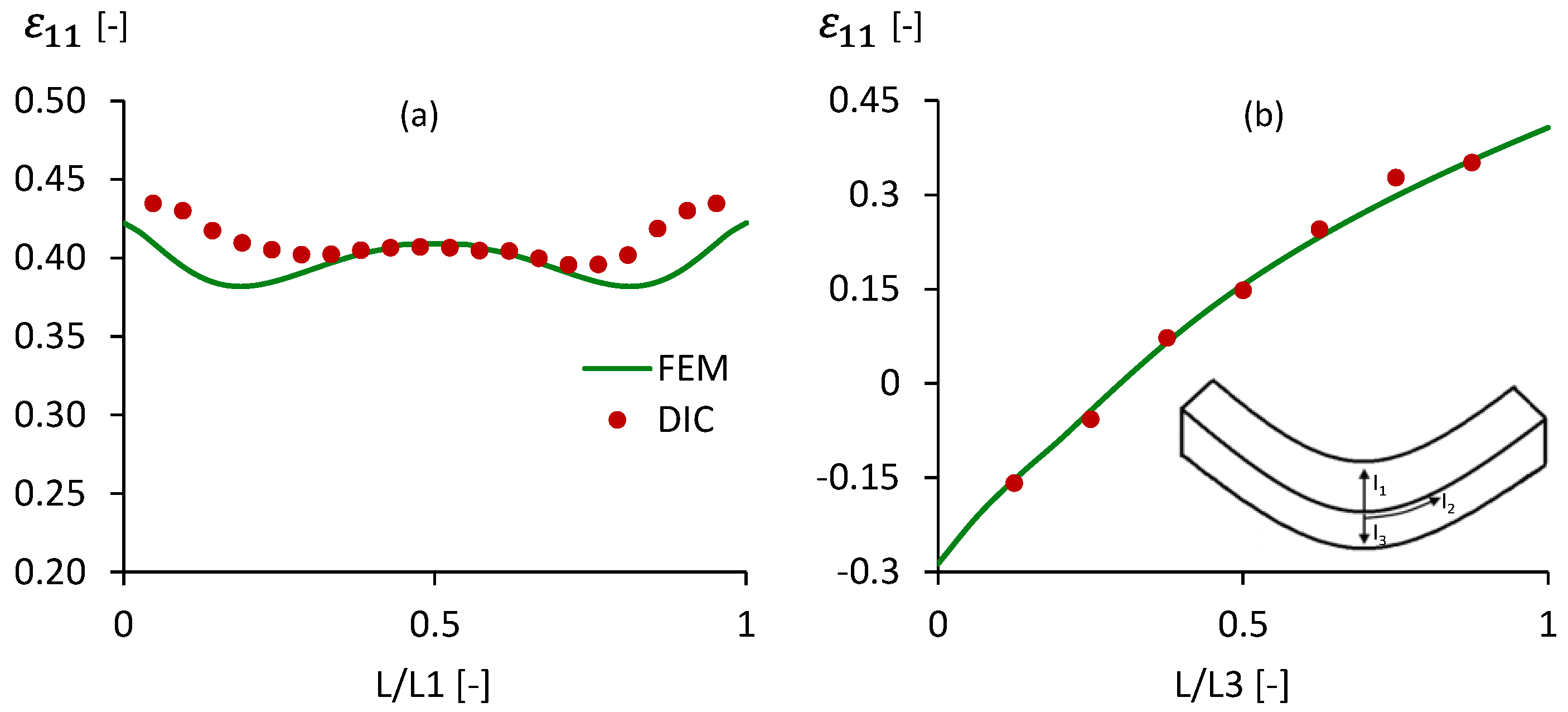
4. Model Validation
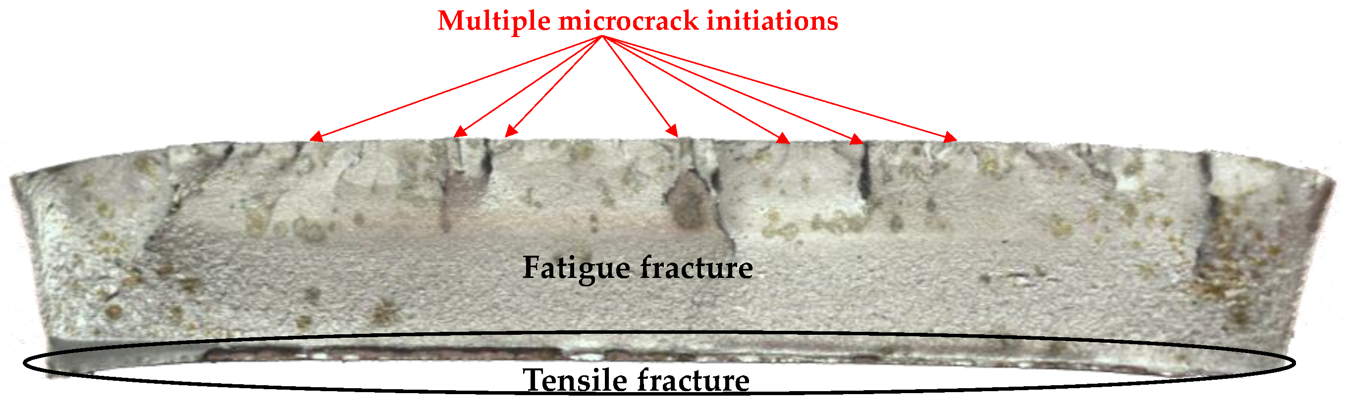
5. Results and Discussion
6. Conclusions
Author Contributions
Acknowledgments
Conflicts of Interest
References
- Azom: S690QL High Yield Structural Steel Properties and applications, 1 June 2010. Available online: www.azom.com. (accessed on 5 April 2018).
- Talemi, R.H.; De Waele, W. Experimental and numerical study on effect of forming process on low-cycle fatigue behaviour of high-strength steel. FFEMS 2017, 40, 2050–2067. [Google Scholar] [CrossRef]
- Vucko, F.; Bosch, C. Experimental investigation of internal and effective stresses during fatigue loading of high-strength steel. J MSEA 2014, 597, 381–386. [Google Scholar] [CrossRef]
- Shimatani, Y.; Shiozawa, K. The effect of the residual stresses generated by surface finishing methods on the VHCF behavior of matrix HSS. Int. J. Fatigue 2011, 33, 122–131. [Google Scholar] [CrossRef]
- Denys, K.; Zhang, H.; Debruyne, D. Report on Basic Material Characterization Obtained with Homogeneous Specimens Only, no Through-Thickness Anisotropy or Inhomogeneity Included; KU Leuven: Gent, Belgium, 2017. [Google Scholar]
- Sutton, M.; Orteu, J.J. Image Correlation for Shape, Motion and Deformation Measurements; Springer: New York, NY, USA, 2009; pp. 81–150. [Google Scholar]
- Schijve, J. Fatigue of Structures & Materials; Springer: Dordrecht, The Netherlands, 2009; pp. 12–134. [Google Scholar]
- Denys, K. Investigation into the Plastic Material Behaviour of Thick HSS Using Multi DIC and FEMU. Ph.D. Thesis, KU Leuven, Gent, Belgium, 2017. [Google Scholar]
- Coppieters, S.; Kuwabara, T. Identification of post-necking hardening phenomena in ductile sheet metal. Exp. Mech. 2014, 54, 1355–1371. [Google Scholar] [CrossRef]


| S690QL | |||
|---|---|---|---|
| RD-AVG | 748.4 ±1.4 | 804.4 ± 1.5 | 37.7 ± 3.6 |
Publisher’s Note: MDPI stays neutral with regard to jurisdictional claims in published maps and institutional affiliations. |
© 2018 by the authors. Licensee MDPI, Basel, Switzerland. This article is an open access article distributed under the terms and conditions of the Creative Commons Attribution (CC BY) license (https://creativecommons.org/licenses/by/4.0/).
Share and Cite
Gothivarekar, S.; Coppieters, S.; Talemi, R.H.; Debruyne, D. Experimental Model Validation and Fatigue Behaviour of Cold-Formed High Strength Steel. Proceedings 2018, 2, 373. https://doi.org/10.3390/ICEM18-05200
Gothivarekar S, Coppieters S, Talemi RH, Debruyne D. Experimental Model Validation and Fatigue Behaviour of Cold-Formed High Strength Steel. Proceedings. 2018; 2(8):373. https://doi.org/10.3390/ICEM18-05200
Chicago/Turabian StyleGothivarekar, S., S. Coppieters, R. H. Talemi, and D. Debruyne. 2018. "Experimental Model Validation and Fatigue Behaviour of Cold-Formed High Strength Steel" Proceedings 2, no. 8: 373. https://doi.org/10.3390/ICEM18-05200