Abstract
Textile reinforced cements (TRC), combining a cementitious matrix with fibre textiles, are a well-researched subject in literature. The material offers several advantages such as the design of low-weight, slender structures. However, one of the main drawbacks of this composite material is the time consuming manufacturing process using two dimensional fibre textiles. Three dimensional fibre textile architectures offer a solution to this problem, while retaining the TRC advantages. Most 3D fibre textiles use distance holders to bridge two, or more textile layers at a certain distance from each other. The influence of this distance holder on the mechanical properties of the whole TRC remains relatively unstudied in literature and will be the research topic of this paper. This research will present the results of three point bending experiments, performed on short TRC beams with a length to thickness ratio of approximately 4 to 1. A comparison is drawn between 3D TRC with fully operational 3D fibre textiles and 2D TRC with the same textile geometry and orientation, but without distance holders. A positive influence on the flexural response is witnessed for the 3D fibre textile, with an increased flexural stiffness up to 35%.
1. Introduction
The ideology behind any composite material is to build one material with desired mechanical properties from a set of different constituent materials with sub-optimal mechanical properties. In the case of Textile Reinforced Cements (TRCs), the constituent materials are a cementitious matrix and fibre textiles. The cementitious matrix on its own possesses an adequate compressive resistance and structural integrity but does not offer the required tensile resistance and ductility desired in most structural applications. The fibre textiles on the other hand offer a decent tensile strength but lack any compressive resistance or structural stability. By combining these two materials as one, a composite is achieved with the ability to withstand compressive loading conditions and furthermore offer a ductile, tensile mechanical response [1,2,3]. Another point of interest of these materials is their ability to achieve relatively slender building systems compared to other, more conventional building materials [1,4,5,6,7].
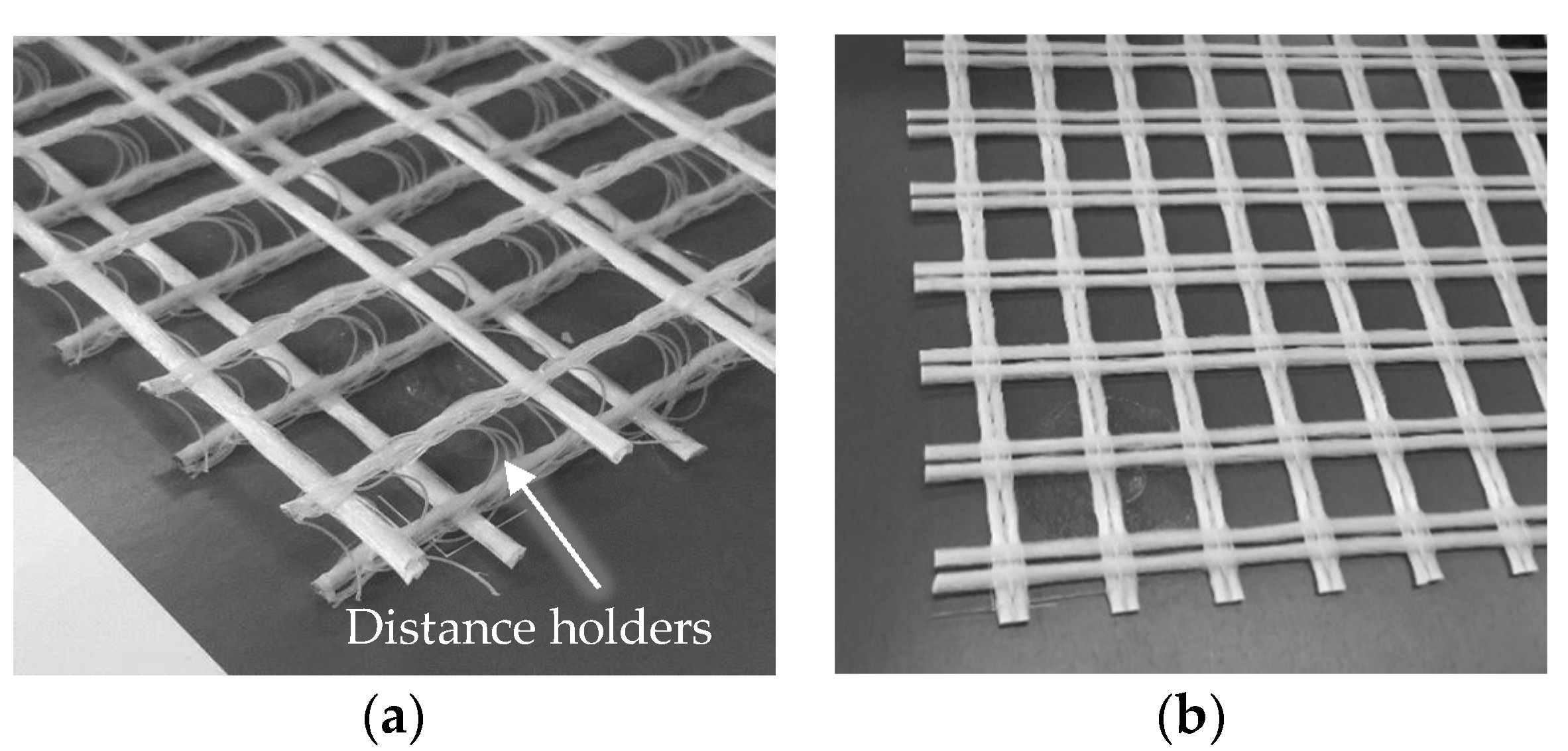
More traditional TRCs are manufactured by combining, usually two dimensional, fibre textile layers with a cementitious matrix. The TRCs researched in this paper however contain three dimensional fibre textiles. 3D fibre textiles are textiles with a three dimensional geometry, which is often achieved by keeping two different fibre textile clusters apart from one another by means of distance holders. These distance holders can be made of the same material as the fibre textiles but they don’t necessarily have to, since their main purpose is not mechanical resistance but geometrical spacing of the fibre textiles. An example of a 3D fibre textile and a 2D fibre textile is given in Figure 1a,b respectively. Several advantages for the use of 3D fibre textiles in TRC are summarized in [8]. For structural applications more specifically, 3D TRC’s lend themselves to a manufacturing process by pouring, rather than for example hand layup, which is in line with the currently used manufacturing processes in construction. A detailed overview of the manufacturing process of these TRCs will be discussed in Section 2.3.
The interest in 3D fibre textile reinforced TRC’s has grown in the last couple of years due to their numerous advantages [9,10,11], however several aspects still need to be researched. This paper will discuss the influence of the distance holder on the flexural mechanical properties of short beams with a length to thickness ratio of approximately 4 to 1. This comparison will be conducted by testing TRCs with four different fibre textile geometries; two with fully operational 3D fibre textiles but a different fibre volume fraction (Vf) and two with the exact same two fibre textile geometries as the 3D ones, but where the distance holders have been cut through. Six specimens for each fibre textile geometry are considered, leading to 24 specimens in total. All displacements are measured by means of Digital Image Correlation (DIC) ([12]), while the reaction force is obtained directly from the test bench.
2. Materials and Methods
2.1. Material Selection
This paragraph will discuss the used materials for the research presented in this paper. As previously discussed the manufacturing process of these 3D TRCs is by means of pouring the cementitious matrix over the fibre textile geometry. Pourability before hardening is therefore one of the most important selection criteria for the matrix material. A commercially available matrix material with maximal grain size of 1.6 mm is chosen, its characteristics are summarized in Table 1, according to [13].

Table 1.
Properties of the commercial matrix material.
For the fibre textiles, the original AR-glass textiles shown in Figure 1a,b are combined to form the desired 3D and cut through fibre textile layups. These layups will be discussed in the following paragraph. The main properties of the original fibre textiles are given in Table 2.

Figure 1.
Image of three dimensional (a) and two dimensional (b) fibre textiles.
Table 2.
Properties of the original fibre textiles.
2.2. Considered Fibre Textile Layups
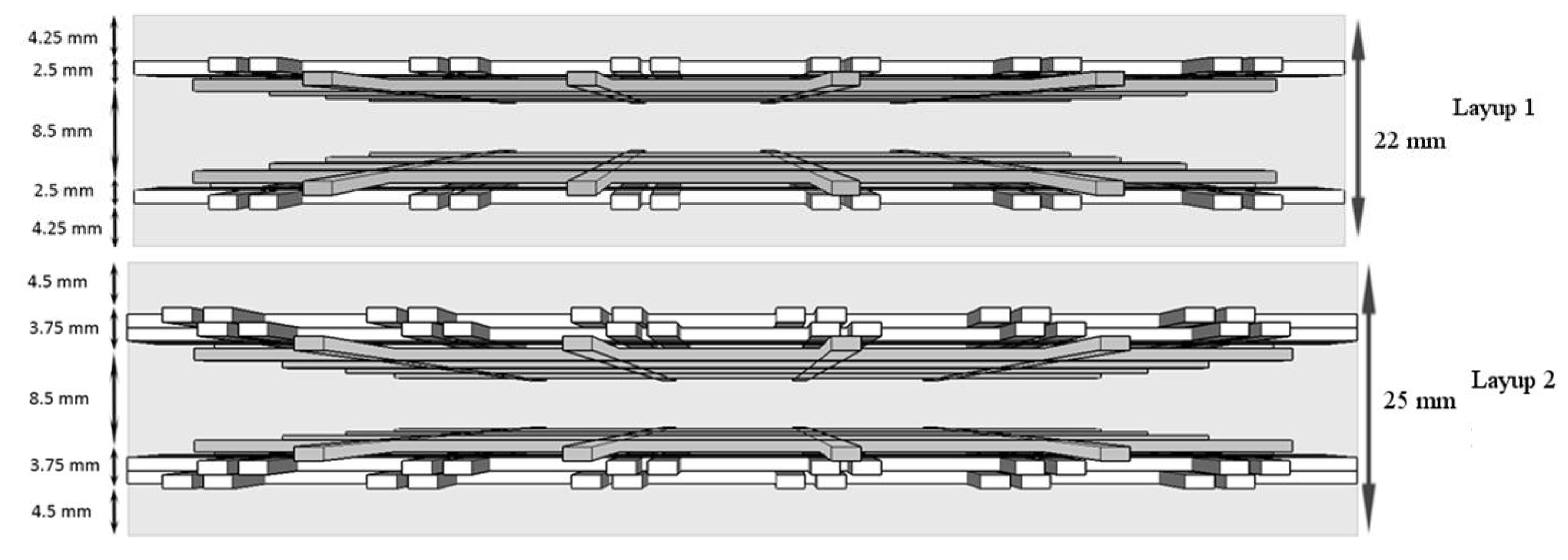
This paragraph will discuss how the original 3D and 2D fibre textiles shown in Figure 1a,b are combined in order to form the two TRC layups considered in this research. There should be noted that for the two considered layups, both a 3D and a cut through alternative have been considered, as previously discussed. The first layup combines one original 3D fibre textile of Figure 1 with two 2D fibre textiles, one on the top and one on the bottom over a total specimen thickness of 22 mm. The two textile clusters, with each a thickness of 2.5 mm, are kept at 8.5 mm from one another in both the connected 3D layup and the cut through layup. The second considered TRC layup is similar to the first one, except that two 2D fibre textiles are added both at the top and at the bottom, resulting in two textile clusters of 3.75 mm thick and a specimen thickness of 25 mm. Figure 2 gives a schematic representation of the two cut through TRC layup alternatives, but both the connected and the cut through alternatives have been tested.

Figure 2.
Schematic representation of the TRC cross-sections for the cut through alternatives.
The reason to opt for a combination of 3D and 2D fibre textiles is that the original 3D textile does not offer the required minimal fibre volume fraction to achieve composite action of the material, the amount of glass fibres inside the TRC cross-section is therefore increased by adding the 2D fibre textiles. Layups 1 and 2 result therefore in a fibre volume fraction of respectively 1.49% and 2.2% in the longitudinal direction of the specimen.
2.3. Specimen Manufacturing Process
The manufacturing of the specimens is achieved by first pre-binding the fibre textiles in the desired layup. This means that independently of the considered layup (connected or cut through, one or two extra 2D textiles on top and bottom) the textiles are bound together by means of nylon wires and the 8.5 mm spacing is achieved by the distance holders for the connected alternative or by manually inserted additional spacers for the cut through one. These additional spacers are cut off afterwards in order not to influence the mechanical response of the material, but ensure a correct textile placement inside the mould. The pre-bound fibre textiles are then placed inside a 450 mm × 500 mm mould, distance holders are again used to ensure the bottom cover thickness of 4.25 mm or 4.5 mm, depending on the desired layup. The next step consists in pouring the pre-mixed mortar over the fibre textiles while holding the mould on a vibrating table to maximize penetration of the matrix inside the fibre textiles. The excess of mortar is then removed by means of a flattening ruler after which the mould is sealed off. The plates are left to harden for 28 days after which the specimens are cut in the desired dimensions of 150 mm × 60 mm × 22 or 25 mm (length × width × thickness) by means of a diamond saw. The last step consists in applying a speckle pattern for the DIC analysis on the side of the specimen.
2.4. Three-Point Bending Test Setup
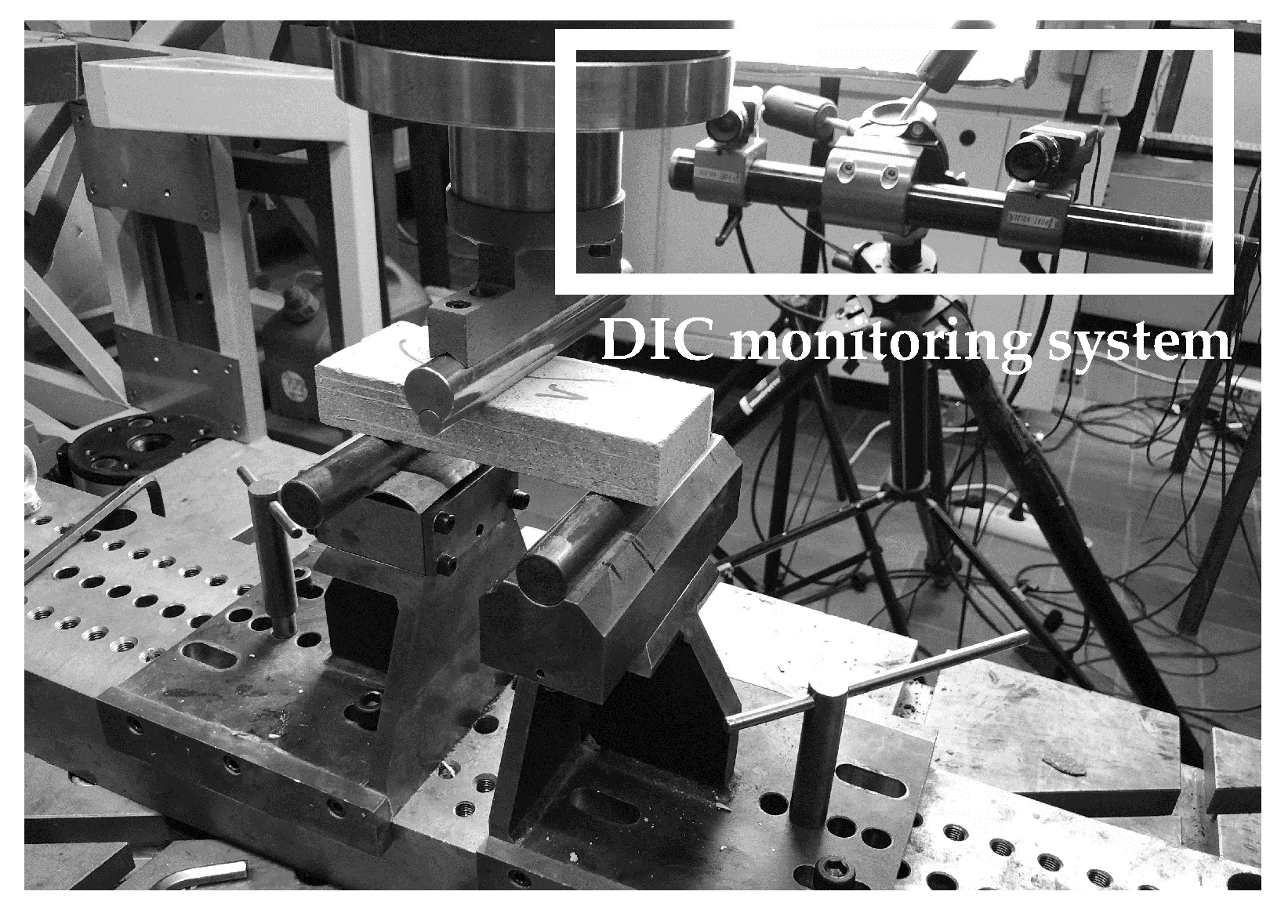
The three point bending test setup used for the experimental campaign is shown in Figure 3 together with the DIC monitoring system. The span is 100 mm and the loading pin is applied centrically in between the supports. The flexural test is performed at a rate of 2 mm/min on an Instron 5885 test bench. The DIC monitoring system, seen in the back of the image, offers a full-field monitoring of the displacement of the back face of the specimen, where a speckle pattern is applied. The cameras follow the relative displacements of the dots of the speckle pattern, offering a measure for the displacement and a visualisation of the cracks present on the surface. More information about this technique can be found in [12].

Figure 3.
Three point bending test setup.
3. Results and Discussion
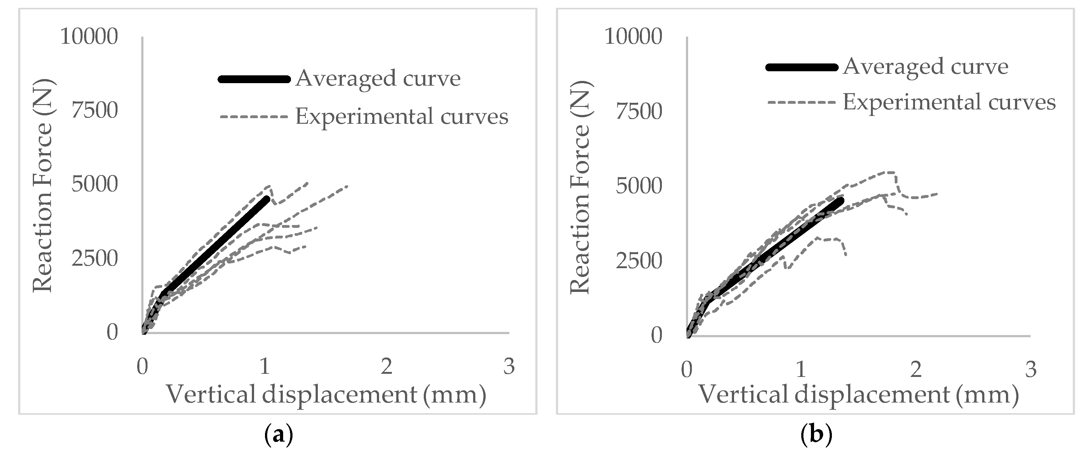
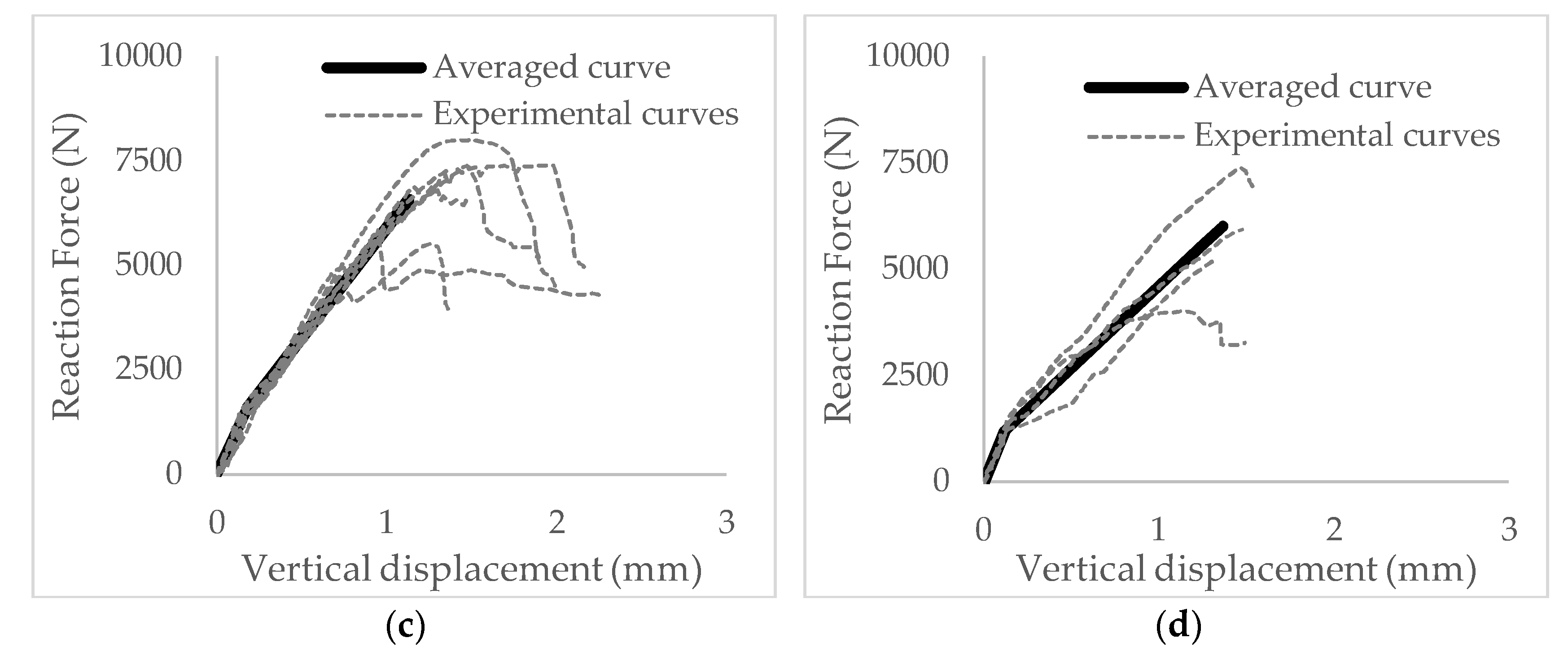
Figure 4 gives an overview of the results obtained from the experimental campaign for the two different layups, both for the connected 3D and the cut through alternative. All experimental curves are plotted as dashed lines and an experimental linearized averaged curve is plotted as a bold black line. The averaged curve is obtained by connecting the averaged value of several representative points of each of the experimental curves, this is thoroughly explained in [10]. The first point is the point of zero force and displacement. The second point is the force and displacement at the end of the linear elastic zone, called fc and dc. The last point is the force and displacement at failure, ff and df.


Figure 4.
Experimental Force (N)—Displacement (mm) results from three-point bending experiments for four considered TRC alternatives; (a): Layup 1, connected TRC; (b): Layup 1, cut through TRC; (c): Layup 2, connected TRC; (d): Layup 2, cut through TRC.
All previously discussed representative points are summarized in Table 3 together with the derived post cracking flexural stiffness (here defined as the force increment divided by the displacement increment) for each one of the considered layups. A clear difference in post cracking stiffness can be witnessed between the different layups. When mutually comparing Layup 1 and Layup 2 a difference in post cracking stiffness related to the volume fraction is witnessed, as is to be expected. However, a more important result is found when comparing the connected and the cut through alternatives, both for Layup 1 and Layup 2. In the case of Layup 1, the ratio between the connected and the cut through alternative is 1.33. A ratio of 1.37 is found in the case of Layup 2, meaning that for both layups the presence of distance holders connecting both fibre textile clusters has a positive influence on the flexural mechanical response of the whole short beam TRC of around 35%. This means that without increasing the fibre volume fraction, the TRC’s flexural stiffness is improved in the post cracking stage.
Table 3.
Representative points from experimental curves and flexural stiffness for each combination.
This improvement in stiffness becomes even more clear when comparing the flexural post cracking stiffness of the connected Layup 1 (3800.60 N/mm, Vf = 1.49%) with the cut through post cracking stiffness of Layup 2 (3854.48 N/mm, Vf = 2.2%). The stiffness values are almost identical, while their fibre volume fraction is not.
4. Conclusions
This paper proposes an experimental campaign performed on two different 3D TRC layups, with each a connected and a cut through alternative. The experimental campaign consists of three-point bending experiments on short beams where six specimens per layup have been tested. The results are obtained from DIC analysis and an Instron test bench. Firstly, an influence of the fibre volume fraction is witnessed on the flexural mechanical response of the material, as can be seen when comparing Layup 1 with Layup 2. Secondly, a clear influence of the distance holder on the flexural stiffness is witnessed when comparing the connected to the cut through layup alternatives. This additional mechanical stiffness is notable to the extent that a TRC with a connected layup of lower fibre volume fraction (1.49%) exhibits a mechanical behaviour similar to that of a TRC with a cut through layup but higher fibre volume fraction (2.2%). Upcoming work will further investigate the influence of these three dimensional distance holders on the mechanical influence of TRCs as well as the possible modelling of these composite materials.
Author Contributions
M.E.K. wrote the main body of the text found in the paper. As promotor of the research, T.T. contributed to the scientific input and review of the manuscript. J.W., S.V., J.V. and M.D.M. contributed to the research and added valuable reviews for the paper. D.V.H. provided the funding for the research.
Acknowledgments
The author would like to thank all contributing parties that made this research possible. This ranges from all contributing authors to the Agentschap Innoveren & Ondernemen that grants the funding for the CeComStruct project that parents this research.
Conflicts of Interest
The authors declare no conflict of interest. The funding sponsors had no role in the design of the study; in the collection, analyses, or interpretation of data; in the writing of the manuscript, and in the decision to publish the results.
References
- Brameshuber, W. Textile Reinforced Concrete—State-of-the-Art Report of RILEM TC 201-TRC, 1st ed.; RILEM: Aachen, Germany, 2006. [Google Scholar]
- Bentur, A.; Mindess, S. Fibre Reinforced Cementitious Composites; Modern Concrete Technology Series; Taylor & Francis: New York, NY, USA, 2007. [Google Scholar]
- Aveston, J.; Cooper, G.A.; Kelly, A. Single and multiple fracture In Properties of Fibre Composites; National Physical Laboratory: Teddington, UK, 1971; pp. 15–24. [Google Scholar]
- Triantafillou, T. Textile Fibre Composites in Civil Engineering, 1st ed.; Woodhead Publishing: Sawston, UK, 2016. [Google Scholar]
- Sharei, E.; Scholzen, A.; Hegger, J.; Chudoba, R. Structural behavior of a lightweight, textile-reinforced concrete barrel vault shell. Compos. Struct. 2017, 171, 505–514. [Google Scholar] [CrossRef]
- Scholzen, A.; Chudoba, R.; Hegger, J. Thin-walled shell structures made of textile-reinforced concrete Part I: Structural design and construction. Concr. Struct. 2015, 16, 106–114. [Google Scholar] [CrossRef]
- Verwimp, E.; Tysmans, T.; Mollaert, M.; Berg, S. Experimental and numerical buckling analysis of a thin TRC dome. Thin-Walled Struct. 2015, 94, 89–97.
- Roye, A.; Gries, T. 3-D Textiles for Advanced Cement Based Matrix Reinforcement. J. Ind. Text. 2007, 37, 163–173. [Google Scholar] [CrossRef]
- Gurkan, P. 3D Woven Fabrics. In Woven Fabrics; InTech: London, UK, 2012; pp. 91–121. [Google Scholar]
- El Kadi, M.; Verbruggen, S.; Vervloet, J.; De Munck, M.; Wastiels, J.; Tysmans, T. Experimental investigation and benchmarking of 3D textile reinforced cementitious composites. In Proceedings of the 4th International Conference on Strain-Hardening Cement-Based Composites, Dresden, Germany, 18–20 September 2017; pp. 1–8. [Google Scholar]
- Peled, A.; Haik, R.; Sasi, E.A. Influence of three-dimensional (3D) fabric orientation on flexural properties of cement-based composites. Cem. Concr. Compos. 2017, 80, 1–9. [Google Scholar]
- Sutton, M.A.; Orteu, J.-J.; Schreier, H.W. Image Correlation for Shape, Motion and Deformation Measurements; Springer Science + Business Media: Berlin, Germany, 2009. [Google Scholar]
- Sika, Sikagrout 217, Note de Produit. Available online: https://fra.sika.com/fr/solutions-produits/marche- construction/voirie/produits-systemes/scellement-calage-grandes-dimensions.html (accessed on 7 November 2017).
Publisher’s Note: MDPI stays neutral with regard to jurisdictional claims in published maps and institutional affiliations. |
© 2018 by the authors. Licensee MDPI, Basel, Switzerland. This article is an open access article distributed under the terms and conditions of the Creative Commons Attribution (CC BY) license (https://creativecommons.org/licenses/by/4.0/).