Abstract
This study focuses on characterizing the transient deformation of test plates which have been exposed to air blasts arising from air-backed and metal-backed explosive detonations. Four charge masses are considered, namely 10 g, 15 g, 20 g and 25 g masses of PE4 plastic explosive which were moulded into cylindrical charges of a constant 38 mm diameter. The transient deformation of the test plates was captured using high speed Digital Image Correlation (DIC), which utilized two high speed cameras to record the experiments. The experimental plates exhibited plastic deformation with no tearing. The impulse imparted to the test plates increased fivefold when the charge was metal-backed. The permanent deflections from the metal-backed detonations were larger than for air, but not to the same degree as the impulse increase.
1. Introduction
The need to protect people, structures and equipment from explosive effects has grown in prominence. Many investigations [1] have examined the influence of material properties and geometry on the response of plates when explosives are detonated in air, although most have not measured the transient response. Recently, Aune et al. [2,3] and Curry and Langdon [4] have successfully used high speed photography and digital image correlation to measure the transient response of plates subjected to blast loads in air. This paper extends the work in reference [4] by looking at the influence of explosive charge backing on the loading and transient deformation response of deformable steel plates subjected to blast loading. The work leverages a numerical model to aid in the understanding of the complex interactions between the explosive gas products and the test plate.
2. Materials and Methods
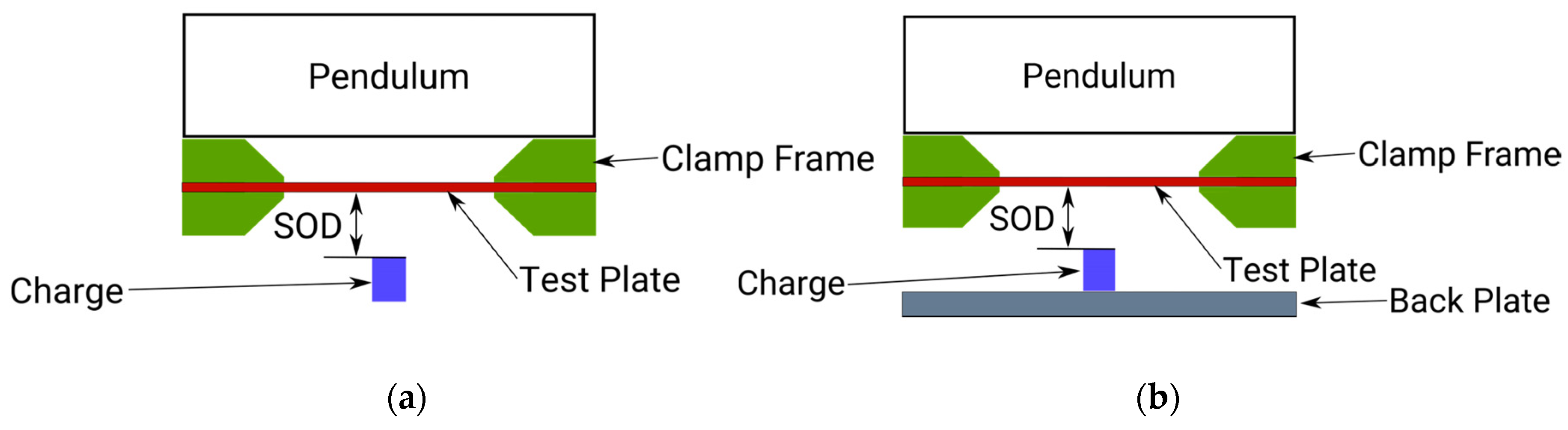
The test plates were manufactured from 3 mm thick Domex 355MC sheet steel. The plates were square with a side length of 400 mm, and a circular exposed area with a diameter of 300 mm when clamped in the test frame. Each test plate was bolted between two chamfered clamp frames using 12 evenly spaced bolts as shown in Figure 1 and Figure 2. The material properties of the test plates was specifically chosen to be ductile with an average strain to failure of 25% [4]. This allowed the two different loading conditions to be directly compared, highlighting the loading conditions effects. Each test plate was cleaned and prepared for painting to enable the Digital Image Correlation (DIC) technique to be used to track the transient displacement of the plate, following ref [4]. The charge was molded into a 38 mm diameter cylinder with a c varying height dependent on the charge mass. The Stand Off Distance (SOD) was measured from the from face of the charge and was set at 40 mm for this set of experiments. Each charge was detonated at the center of the rear face of the charge using an electrical detonator. An electrical synchronous trigger was used to record the images for each test on two high speed monochrome IDT NRS4 cameras filming at 30,000 fps. Each camera was focused on the central strip through the middle of the test plate, resulting in data reflecting the transient displacement on the central midpoint as well as the cross section of the whole plate.
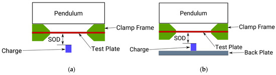
Figure 1.
Schematics showing section views of the two experimental configurations, one with an air-backed charge (a) and one with a metal-backed charge (b).
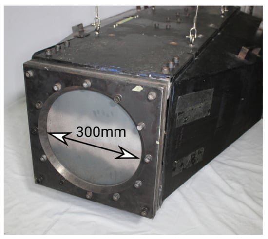
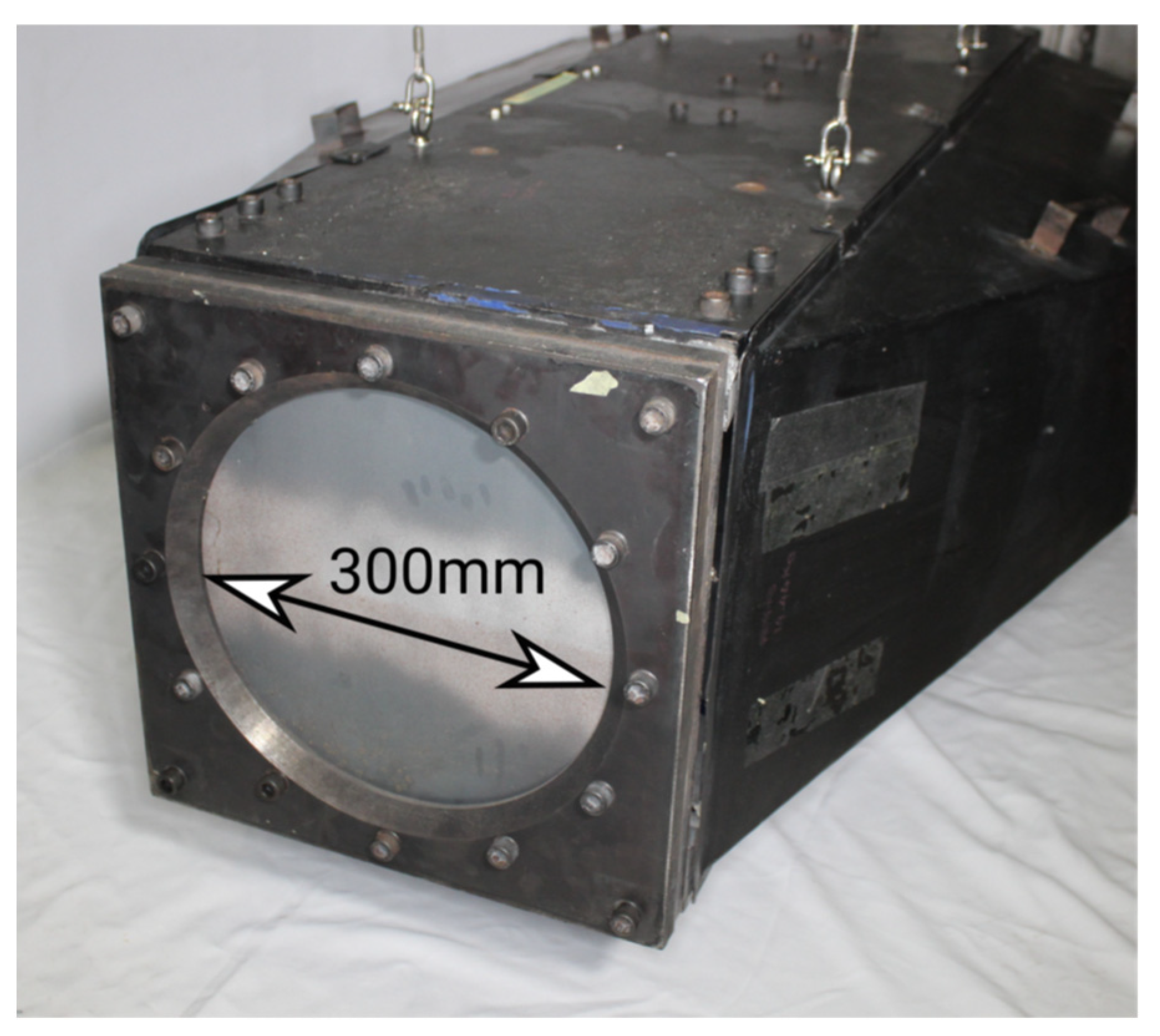
Figure 2.
Photograph of a test plate loaded into the clamp frame and mounted on the horizontal pendulum.
A numerical model was developed to aid in the understanding of the transient deformation of the test plate. The test plate, clamp frame and explosives were modelled using the Multi Material Arbitrary Lagrange Eulerian (MMALE) Fluid Structure Interaction (FSI) approach in Ls-Dyna. The model can be seen in Figure 3 which shows the quarter symmetry representation of the model.
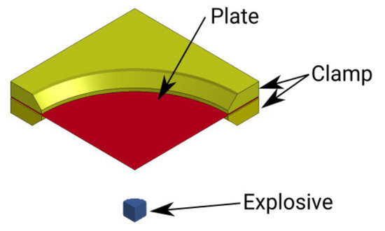
Figure 3.
Quarter symmetry representation of the numerical model.
The plate was modelled using a Johnson Cook (MAT15) material model in Ls-Dyna which was calibrated using tensile test data [4]. The clamp frames were modelled as rigid bodies and the bolted connections were represented as spring elements to simulate the clamping force. Tracer points were placed in the model to predict the pressure at discrete points along the front face of the test plate. These points were selected to be at 20 mm intervals from the plate center with an additional point placed 10 mm from the center. These points were selected to line up with the experimental data collected by Rigby et al. [5] and this information could be used to extrapolate the specific impulse and velocity profile imported on the numerical plates.
3. Results
All the plates, for both the metal-backed and air backed charge detonations, exhibited Mode 1 (that is large plastic deformation) failure without any indication of tearing or shearing failures.
3.1. Impulse Comparison
Metal backed charge detonations increased the impulse measured on the pendulum, as shown in Figure 4. There was an average increase of 78 Ns, througout the charge range, when the back plate was introduced.
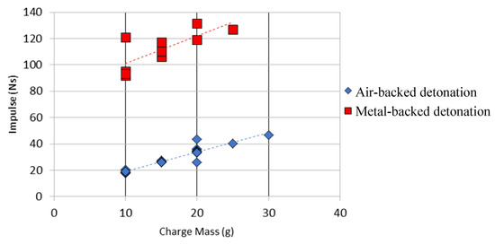
Figure 4.
Impulse vs. Charge mass for the air and metal backed charge detonations.
3.2. Displacement Comparison
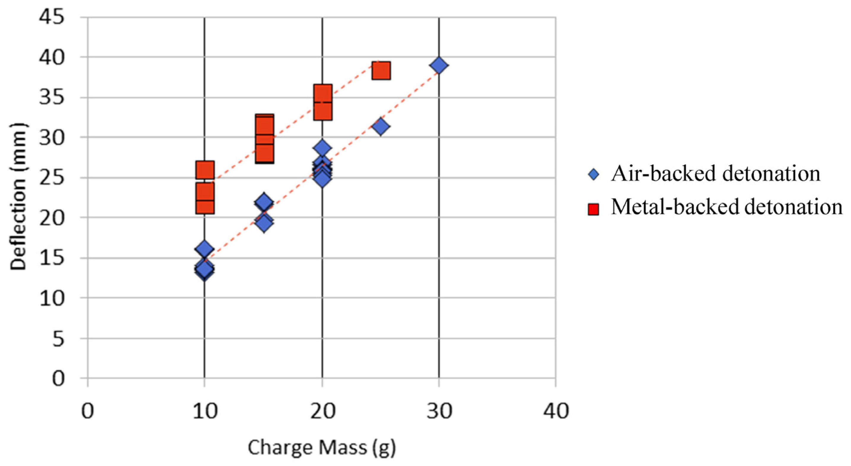
A summary of the permanent and transient deflections is shown in Table 1. The peak transient deflections are larger than the permanent deflections, as expected, with a typical elastic recovery of 2–3 plate thicknesses (slightly larger than expected). A graph of final midpoint deflection versus charge mass is shown in Figure 5 for the two types of charge backing. The mid-point deflection increases linearly with increasing charge mass for a given charge backing. The metal backing increased the permanent mid-point deflection of the plates, as might be expected due to the large increase in impulse transfer. However, the difference in deflection is smaller than the rise in impulse, indicating that the releationship between impulse transfer and plate deflection is not straightforward.

Table 1.
Table showing average midpoint deflections obtained from the experiments.

Figure 5.
Graph of midpoint permanent deflection versus charge mass for the air and metal-backed charge detonations.
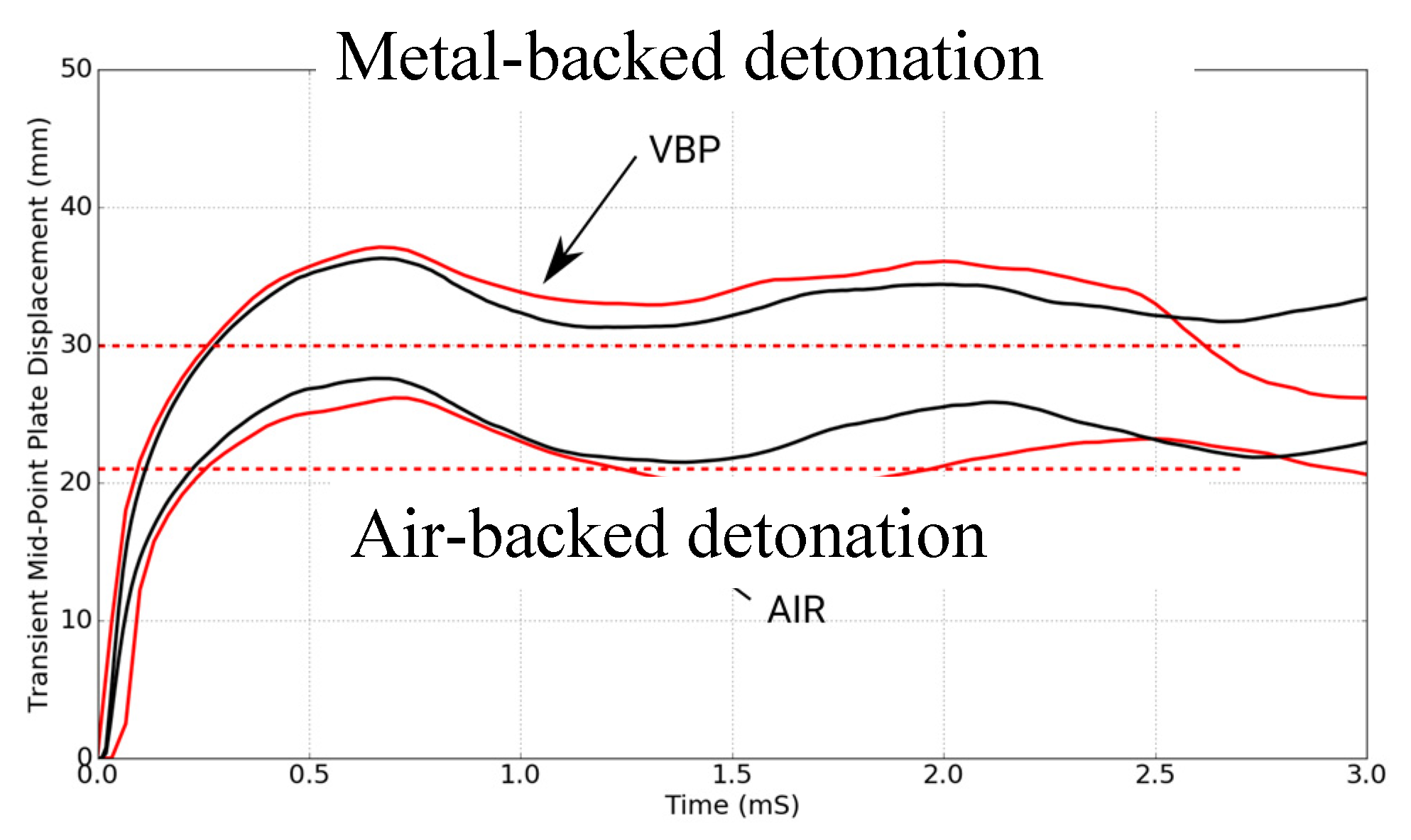
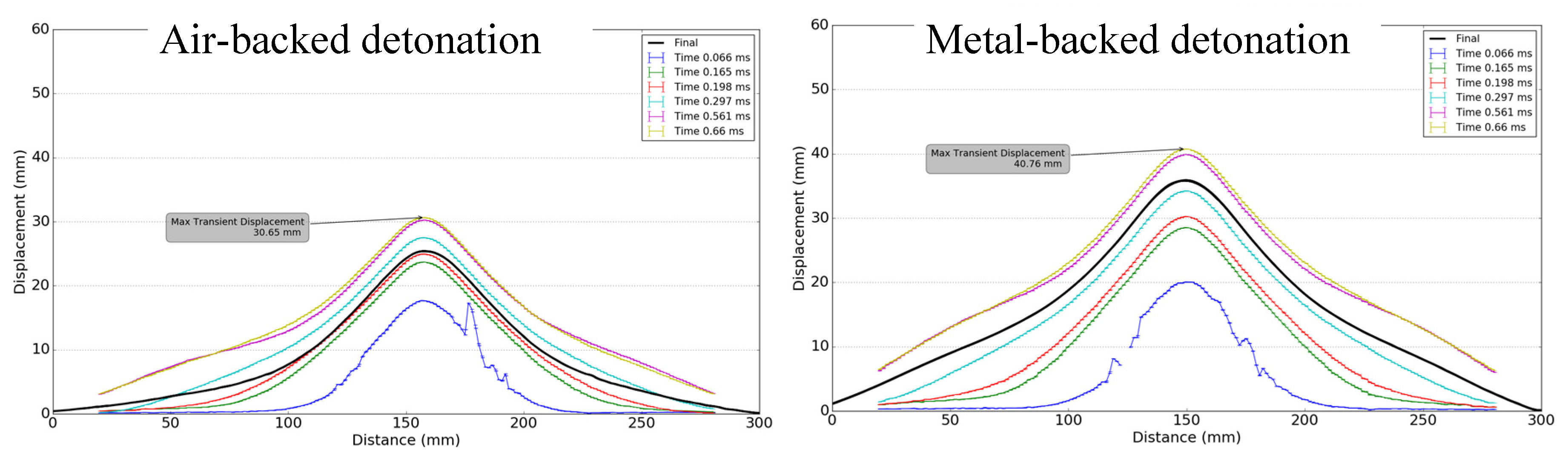
The transient midpoint responses of the plates, obtained from DIC on images from the 20 g charge detonations, are shown in Figure 6. The displacement resulting from metal-backed detonation does not rebound below the dashed line of final deformation in the first 2 ms, in contrast to the air-backed detonation response. This is like that seen in buried charge explosions which have a longer loading phase due to the ejecta impinging on the test plate [4,6]. It appears that there is some extended loading duration for the metal-backed detonation not present in the air-backed configuration. The plate profiles are shown in Figure 7. The metal backing localized the deformation to the centre.
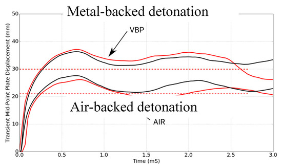
Figure 6.
The transient midpoint deflections obtained using DIC (red) for typical 20 g charge detonations (experimental values) and the numerical simulation results (black). The dashed lines indicate the permanent deflection.
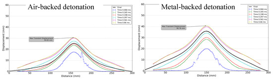
Figure 7.
The transient plate profiles for the 20 g detonations at discrete time intervals (color) and the final deformed plate profile (black).
3.3. Insights from Numerical Simulations
Figure 8 shows plate velocity and specific impulse predictions for 20 g detonations for both charge configurations. The pressure values obtained from the Ls Dyna simulations indicated that the pressure readings across the whole plate were higher for the metal backed charge detonations. This is evidently shown in the specific impulse data, shown in Figure 8b, which represents the integral of the pressure time data across the plate. The increase in impulse at the boundary in the metal-backed detonation simulations shows that the clamp frame produced a recirculation effect (leading to pressure accumulation) along the clamp boundary [7] that was not present in the air-backed charge detonations.
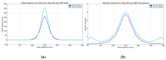
Figure 8.
The simulation plate velocity (a) and specific impulse (b) for the 20 g detonations.
Additionally, the metal-backed charge detonation causes reflected pressure from the metal surface towards the test specimen in the region of the charge. This reflection produced a localised increase in the initial plate velocity, shown in Figure 8a. This localisation effect of the metal backing caused a 40% increase in plate velocity at the mid-point position at 30 µs after detonation. This combination of recirculated pressure accumulation at the clamp boundary and the pressure reflection from the charge detonation on the metal backing surface caused he increased impulse transfer to the plate. The recirculated pressure at the clamp is known to increase the impulse transfer without producing a similar increase in plate deflection [7]. This is a reason why the experimentally obtained plate deflections did not increase as significantly as the impulse increased when the metal backing was used.
4. Concluding Comments
Experiments and simulations were performed to ascertain the influence of charge backing on the response of plates subjected to blast waves arising from the detonation of plastic explosives. The experiments showed that the impulse imparted to the test plates increased fivefold when the charge was metal-backed. The permanent deflections from the metal-backed detonations were larger than for air, but not to the same degree as the impulse increase. The simulations revealed two reasons for the increased impulse transfer: pressure recirculation along the clamp not present in the air-backed detonations, and a localised increase in the initial plate velocity in the region of the charge. The localised increase in velocity was due to reflected pressure from the metal back plate towards the test specimen just after detonation. This influenced the deformation of the plate but did not account for the fivefold increase in impulse. The pressure recirculation at the clamp occurred over a larger area and longer duration, causing the impulse to increase without a corresponding rise in plate deflection.
Author Contributions
The experiments and data presented in this paper form part of the data set created during the PhD work of R.C. supervised directly by G.L. The paper was written by G.L. and R.C.
Acknowledgments
The authors are grateful to the UCT University Research Committee, The David and Elaine Potter Foundation and the National Research Foundation (NRF) of South Africa for their financial support. Opinions expressed and conclusions arrived at, are those of the authors and are not necessarily to be attributed to the NRF. The donations of Domex steel from SSAB and Vulcan Steel are gratefully acknowledged. The authors would also like to thank the staff of the Mechanical Engineering workshop at UCT for their assistance in machining the specimens and pendulum parts.
Conflicts of Interest
The authors declare no conflict of interest
References
- Yuen, S.C.K.; Nurick, G.N.; Langdon, G.S.; Iyer, Y. Deformation of Thin Plates Subjected to Impulsive Load: Part III—An Update 25 years on. Int. J. Impact Eng. 2017, 107, 108–117. [Google Scholar] [CrossRef]
- Aune, V.; Fagerholt, E.; Hauge, K.; Langseth, M.; Børvik, T. Experimental study on the response of thin aluminium and steel plates subjected to air blast loading. Int. J. Impact Eng. 2016, 90, 106–121. [Google Scholar] [CrossRef]
- Aune, V.; Valsamos, G.; Casadei, E.; Larcher, M.; Langseth, M.; Børvik, T. Numerical study on the structural response of blast-loaded thin aluminium and steel plates. Int. J. Impact Eng. 2017, 99, 131–144. [Google Scholar] [CrossRef]
- Curry, R.J.; Langdon, G.S. Transient response of steel plates subjected to close proximity explosive detonations in air. Int. J. Impact Eng. 2017, 102, 102–116. [Google Scholar] [CrossRef]
- Rigby, S.E.; Fay, S.D.; Clarke, S.D.; Tyas, A.; Reay, J.J.; Warren, J.A.; Gant, M.; Elgy, I. Measuring spatial pressure distribution from explosives buried in dry Leighton Buzzard sand. Int. J. Impact Eng. 2016, 96, 89–104. [Google Scholar] [CrossRef]
- Pickering, E.G.; Yuen, S.C.K.; Nurick, G.N.; Haw, P. The response of quadrangular plates to buried charges. Int. J. Impact Eng. 2012, 49, 103–114. [Google Scholar] [CrossRef]
- Bonorchis, D.; Nurick, G.N. The effect of welded boundaries on the response of rectangular hot-rolled mild steel plates subjected to localised blast loading. Int. J. Impact Eng. 2007, 34, 1729–1738. [Google Scholar] [CrossRef]


Publisher’s Note: MDPI stays neutral with regard to jurisdictional claims in published maps and institutional affiliations. |
© 2018 by the authors. Licensee MDPI, Basel, Switzerland. This article is an open access article distributed under the terms and conditions of the Creative Commons Attribution (CC BY) license (https://creativecommons.org/licenses/by/4.0/).