Proceeding Paper

Analytical Calculation of Load Tests of Curved Ceiling Elements Made of Carbon Concrete and Nonwovens Impregnated with Concrete †

by
Tilo Senckpiel
* and
Ulrich Häußler-Combe
Institute of Concrete Structures, Technische Universität Dresden, 01062 Dresden, Germany
*
Author to whom correspondence should be addressed.
Presented at the 18th International Conference on Experimental Mechanics (ICEM18), Brussels, Belgium, 1–5 July 2018.
Proceedings 2018, 2(8), 476; https://doi.org/10.3390/ICEM18-05357
Published: 15 June 2018
(This article belongs to the Proceedings of The 18th International Conference on Experimental Mechanics)

Abstract

:
Carbon reinforced concrete (in short: carbon concrete) allows thin cross sections and lightweight, high-strength structures. This is demonstrated in this article using the example of a lightweight, prefabricated ceiling girder. In addition to the new building material carbon concrete, another innovative cement-bonded composite material is used: concrete-impregnated nonwovens. The ceiling element is a very light, slim construction that is curved in the transverse direction. In addition to the material and construction, the article describes the experimental investigation and the possibility of calculation using an analytical approach.

1. Introduction

The construction of carbon concrete opens up many new possibilities [1]. Carbon reinforcement, for example, is not susceptible to corrosion due to normal atmospheric influences. This means that no concrete cover is required, which is only necessary to protect the reinforcement against corrosion. Compared to reinforced concrete, much thinner cross sections with the known positive effects in terms of dead weight and thus in terms of resource consumption and sustainability can be achieved in many areas of application. For this purpose, the concept of a prefabricated lightweight ceiling girder made of carbon concrete is described below. In addition to the general saving of resources, the extensive reduction in dead weight is also intended to facilitate handling during assembly. The article is aimed at extending the numerical investigations [2] by a more easily applicable, analytical approach.

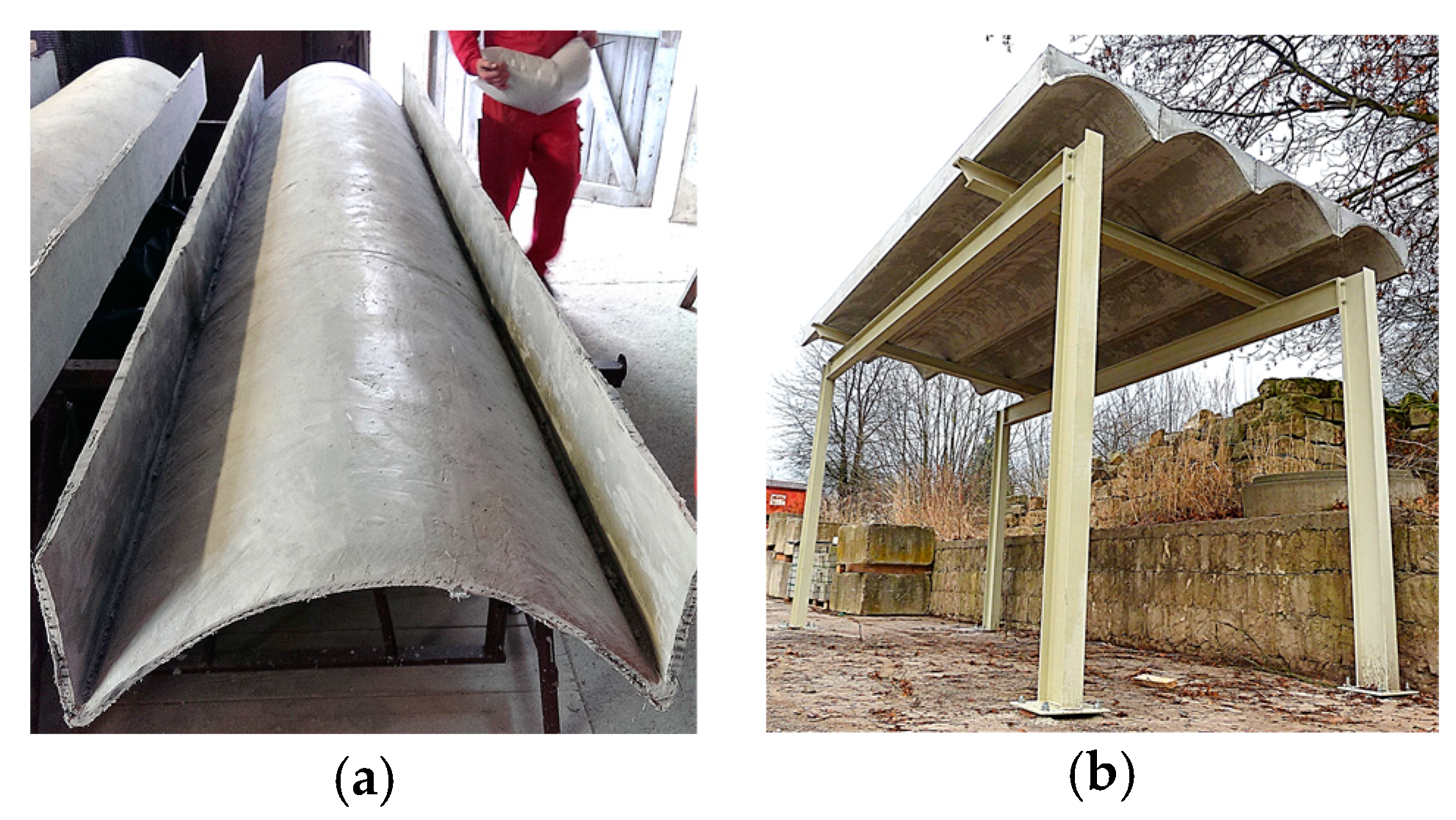
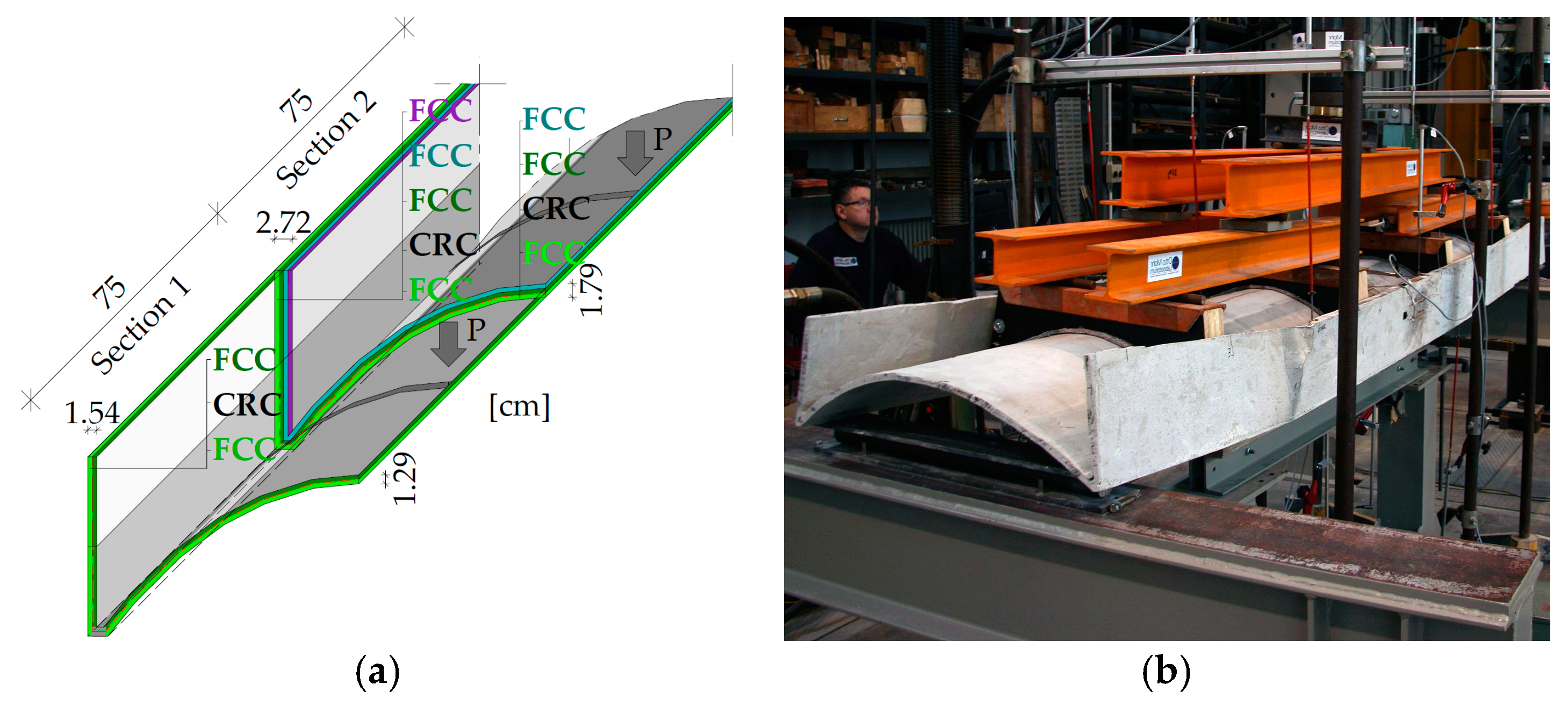
2. Design of the Ceiling Element

Within the scope of the research project, various construction variants and spans from 3 m to 4.3 m of the lightweight ceiling element were realized and subsequently tested experimentally [2]. The elements can be used e.g. as prefabricated components to replace old floor slabs in existing buildings. A partial goal in the project was to reduce the weight so that manual assembly or the use of only light hoists is possible. In Figure 1, the usage scheme is shown based on the realized demonstrator and the calculated construction. Only textile carbon reinforcement is used.
The height of a ceiling element is limited to 20 cm in order to fit into existing ceiling constructions. The shell arch is formed in transverse direction along a chain line. The base thickness is 1.3 cm, which has been increased up to 2.7 cm in some areas to improve overall stiffness.

3. Materials

The base material is a composite of two outer layers and a core layer (Figure 2a). The former is a concrete-impregnated nonwoven fabric (see Figure 2b) developed in cooperation with BCS Natur- und Spezialbaustoffe GmbH and BCS Baustoff Control Service GmbH & Co. KG, Dresden (Germany), the Sächsisches Textilforschungsinstitut e.V. STFI, Chemnitz (Germany), and our Institute of Concrete Structures. The core layer consists of fine-grained concrete reinforced with carbon fiber grids.

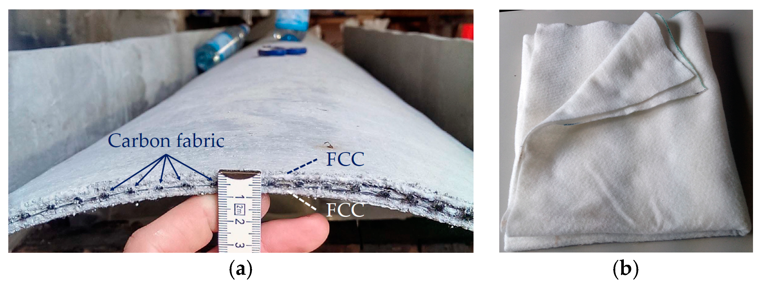
3.1. Composite Material

The basic material for the outer layers is a needle punched nonwoven made of polypropylene fibers specially developed for the impregnation with concrete. The largest grain size of the fine concrete matrix is limited by the opening widths of the nonwoven. The thickness of a soaked layer of nonwoven FCC (Fleece Concrete Composite) is 5 mm, enables simple production of components and serves as a carrier material in the formwork for the carbon textiles. It causes a very fine crack pattern and is extremely ductile. The symmetrical cross-sectional structure with FCC as outer layers and carbon reinforced concrete (CRC) as core is shown in Figure 3.

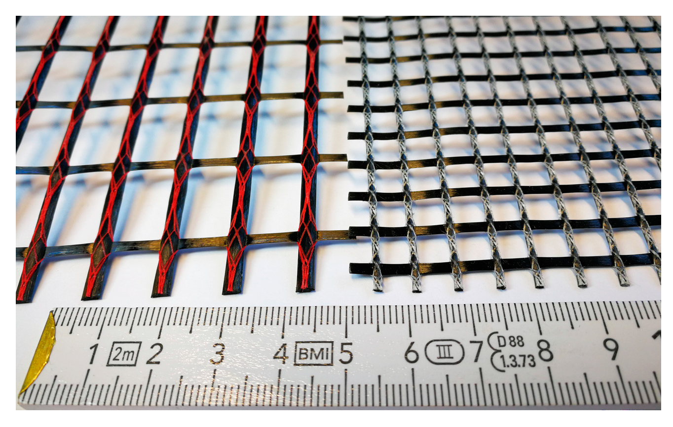
3.2. Carbon Reinforcement

The reinforcement of the ceiling elements consists of two types of carbon mesh (see Figure 3). The fabric type I has a yarn fineness of 3300 tex in warp direction and a corresponding reinforcement of 1.713 × 10⁻⁴ m2/m. In weft direction there are 800 tex and a reinforcement of 3.080 × 10⁻⁵ m2/m. The mesh type II has a fineness of 800 tex in both directions and thus as reinforcement 6.160 × 10⁻⁵ m2/m.

4. Experimental Tests

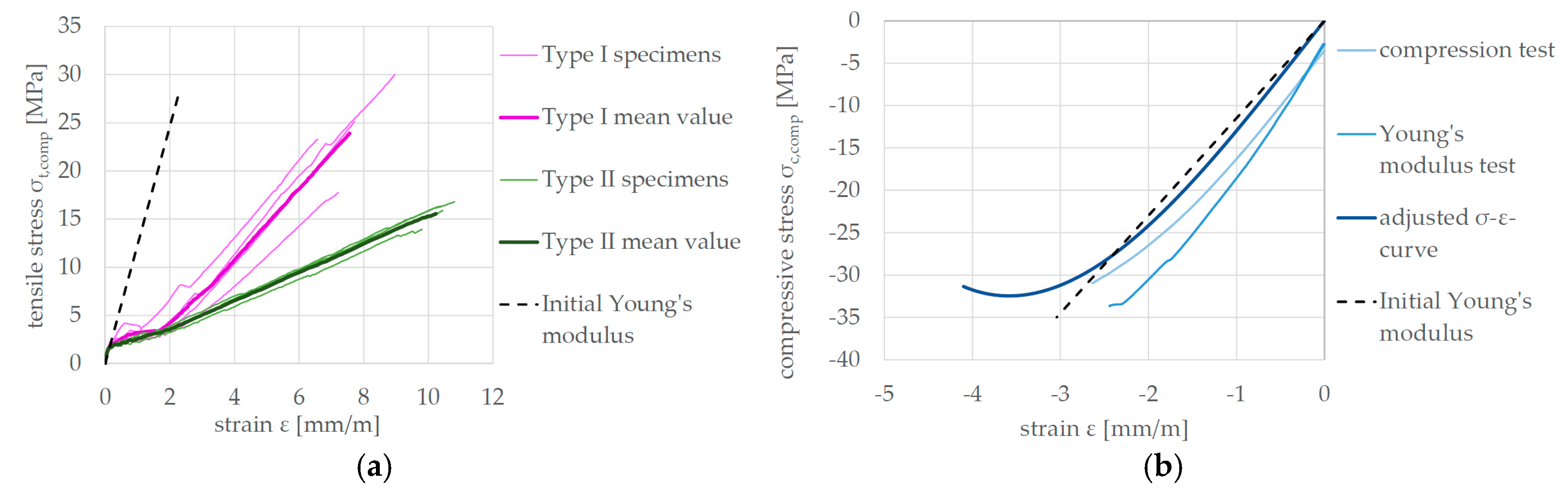
4.1. Composit Material

During the development of the composite material, a series of tensile tests was carried out on unreinforced and reinforced tensile specimens in order to obtain the uniaxial stress-strain behavior of the material combination. The dimensions of the tensile specimens are based on the investigations by Schütze et al. [3]. The samples were 700 mm long, 58 mm wide and 5.55 mm high. The results of the tensile tests are shown in Figure 4. The initial Young’s modulus under tensile loading can be specified with Et = 12,300 MPa. If the force is not related to the entire cross section, but only to the cross section of the yarns, the modulus of elasticity is 170,000 MPa for the type I textile and 193,000 MPa for the type II textile.
The material behavior under uniaxial compressive stress was determined with the use of specimens from undamaged areas of the ceiling elements after the large-scale tests (see 4.2) were carried out. These samples contain the minimum reinforcement of type I textile present in the upper cross section. The dimensions of the specimens were: 60 mm long, 10 to 16 mm wide and 40 mm high and therefore do not comply with a standard. Nevertheless, tests according to [4] for determining the compressive strength and additionally according to [5] for determining the modulus of elasticity were carried out. The tests have been made with the use of strain gauges to gain the adjusted stress-strain curve, which can be taken from Figure 4b. The initial modulus of elasticity for compressive loading of Ec = 11,500 MPa is very similar to the initial modulus of elasticity for tensile loading Et.

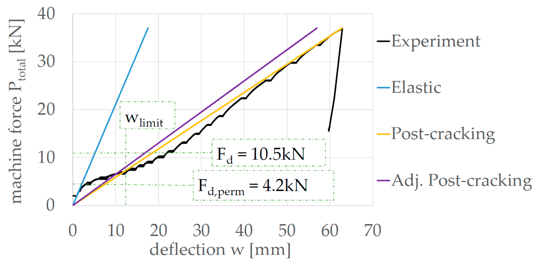
4.2. Ceiling Element Tests

The ceiling element construction presented here results from the experiences of previous variants. Compared to the elements from the beginning of the project, the ceiling elements have been increased in their thickness in the element center in order to minimize the high deflections of lighter constructions through the use of additional nonwoven layers. The components remain below the limit of 1/250 of the span generally specified in EC2-1-1 [6], which is permitted under a quasi-permanent load combination and this was achieved with a grammage of only 0.44 kN/m². The length of the ceiling elements is 3.2 m and the span 3.0 m. The cross-sectional dimensions are shown in Figure 5a. The experimental setup is shown in Figure 5b. The loads are transferred via a load distribution system using four 10 cm wide wooden templates, which results in a 6-point bending test. The distance between the templates is 1/4 of the span and 1/8 to the supports.
The maximum reached load Ptotal = 37 kN is remarkably high and exceeds the design load for ordinary use of 10.5 kN. The compression failure occurs in the upper part of one of the webs (see Figure 5b).

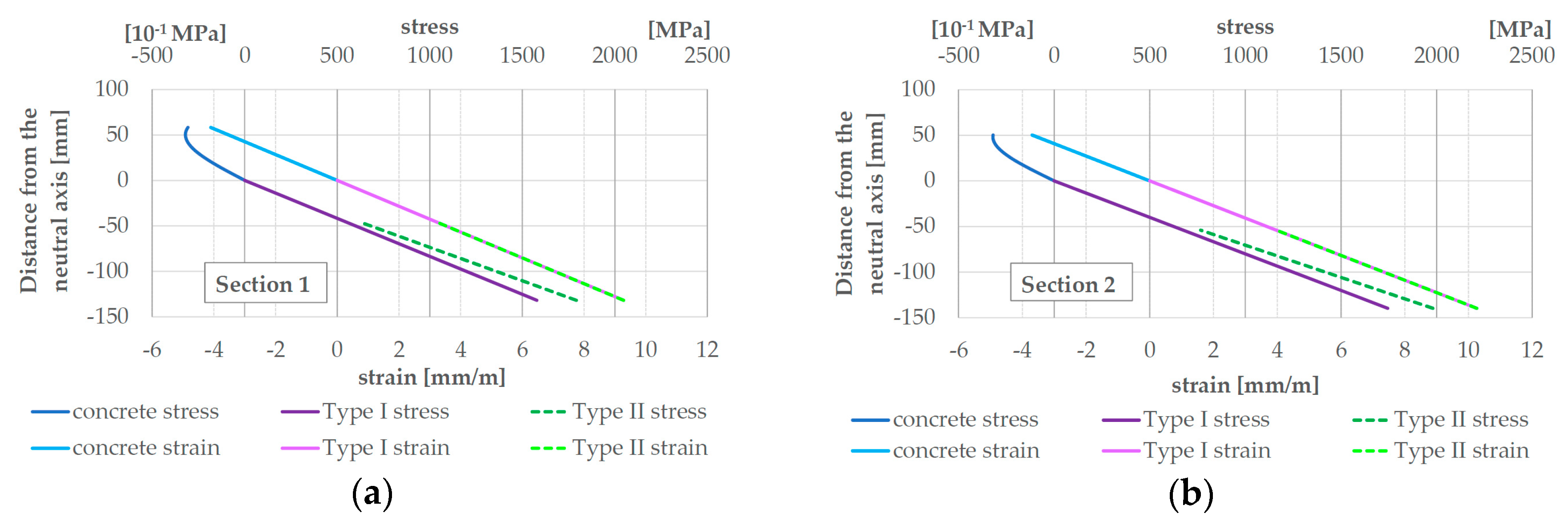
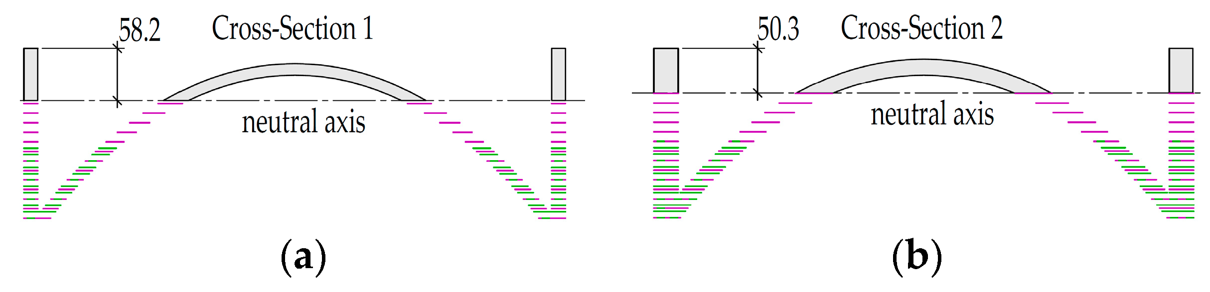
5. Analytical Approach

The analytical approach for calculating the force-deflection curve of the 6-point bending test is based on the principle of virtual forces. The trilinear load-bearing behavior of the experimental ceiling element test in Figure 8 (black line in Figure 8) is typical for reinforced concrete components and results from the change in material state (uncracked, crack formation and final crack pattern) and geometric state of the cross sections. In order to determine these states, a plane strain distribution is assumed in the cross section and the stresses and the equilibrium of internal forces are determined iteratively.

5.1. Elastic State

The calculation of the moments of inertia I1 and I2 assume fully activated and non-cracked cross sections of the two differently dimensioned sections shown in Figure 5. Using the CAD program AutoCAD, the moments of inertia I1 = 4.67 × 107 mm4 (Section 1, outer areas) and I2 = 6.63 × 107 mm4 (middle part of the element, Section 2) can be obtained. According to [7] (p. 393), the principle of virtual forces can be used to calculate the deflection of the center of a beam. For this purpose, the bending moment curve for the 6-point bending test carried out in the experiment and the curve of the moment, which results from the virtual force applied in the middle, are determined for the single-span beam. By integrating the diagrams of the two moments, the formula for calculating the deflection w as a function of the force P [kN] can be established according to [8]:
w = (0.241/EI1 + 1.204/EI2)∙P.
For consistency reasons (determination of the start and end of the crack formation state), the value Et = 12,300 MPa from Figure 3a is used for the first, elastic range. When the material and geometry parameters are used, the following equation for calculating the deformation as a function of the force for the elastic load range results according to [8]:
w = 1.897 mm/kN∙P.
Since the method of virtual forces has been applied to the 6-point bending test with the 4 load transmission points, it should be noted that the force P in the equation corresponds only to a quarter of the applied machine force Ptotal.

5.2. Final Crack State

To determine the slope in the final crack state, the iterative calculation method is used to determine the maximum load and thus the final state of the strain distribution in the cross section. This results in the minimum moments of inertia of the cross sections of the element. The iterative process starts by assuming maximum strains on the outside of the cross section—on the tensile-stressed side for the textile and on the compression-stressed side for the concrete. The neutral axis, the strain of the concrete and the yarns are then determined using linear interpolation. The stresses in the carbon yarns can be calculated using Hooke’s law for elastic material behavior and subsequently the corresponding internal tensile forces by using the yarn cross sections. The concrete force results analogously from the integration of the cubic curve of Figure 4b and the compression-stressed cross section. If the sum of the resulting forces is zero, iteration is complete. Otherwise the assumed cross sectional strains must be varied. Figure 6 shows the strain distribution over the respective cracked cross sections (Figure 7) and the corresponding stress distributions.
After calculating the position of the neutral axes, the moments of inertia of the cracked cross sections Icr,1 and Icr,2 can be calculated. Using the ratio n of the modulus of elasticity of the carbon yarns used and the concrete in Section 4, the moment of inertia is obtained:
Icr,i = Iconcrete,i + Σ(n∙Atex∙d²),
where d is the lever arm between the respective yarn and the neutral axis and Atex is the yarn cross-sectional area. According to [8] this results in an moment of inertia of Icr,1 = 1.55 × 107 mm4 for the first cross section and Icr,2 = 1.77 × 107 mm4 for the second. After substitution of the values in equation 1 the following is obtained:
w = 6.791 mm/kN∙P.
Figure 8 shows the course of the force deflection line (yellow). It can be seen that the slope of the calculated curve differs from the experimentally determined curve in state II.
According to Zilch et al. [7] (p. 394), a component can be divided into non-cracked and cracked areas, with the bending stiffness gradually decreasing in the transition area. To simplify matters, it is subsequently assumed that cross Section 2 is completely cracked and cross Section 1 is cracked at the point of transition to cross Section 2 and is non-cracked in the area near the support where no bending moment occurs. According to [8] this results in the mean value of IMW = 3.11 × 107 mm4. If I1 is now substituted with IMW from Equation (1), the equation is obtained:
w = 6.16 mm/kN∙P.
The adjusted result (purple) is shown in Figure 8 and shows a parallel course to the state II of the experiment.

6. Conclusions

The calculation of the load-bearing behavior of the ceiling element with the analytical approach not only shows the slope of the load-bending curve, but also shows the same type of failure in accordance with the load-bearing test carried out experimentally, whereby reaching the compressive strength of the concrete at the place of the thinnest cross section with simultaneous greatest load causes failure and not by the tensile strength of the textile.

Author Contributions

T.S. designed, performed and analyzed the experiments; Ahmad Chihadeh has implemented the analytical approach under supervision of T.S. T.S. and U.H.-C. wrote the paper.

Acknowledgments

The presented project was funded by the German Federal Ministry of Economic Affairs and Energy (BMWi) on basis of a decision by the German Bundestag.

References

  1. Schladitz, F.; Tietze, M.; Lieboldt, M.; Schumann, A.; Garibaldi, M.P.; Curbach, M. Carbon reinforced concrete in construction practice. In Proceedings of the IABSE Conference—Engineering the Developing World, Kuala Lumpur, Malaysia, 25–27 April 2018. [Google Scholar]
  2. Senckpiel, T.; Häußler-Combe, U. Model comparisons for a shell structure made of textile reinforced concrete. In Proceedings of the Conference on Computational Modelling of Concrete and Concrete Structures (EURO-C 2018), Bad Hofgastein, Austria, 26 February–1 March 2018; pp. 819–828. [Google Scholar]
  3. Schütze, E.; Bielak, J.; Scheerer, S.; Hegger, J.; Curbach, M. Uniaxial tensile test for carbon reinforced concrete with textile reinforcement. Beton Stahlbetonbau 2018, 113, 33–47. [Google Scholar] [CrossRef]
  4. Testing Hardened Concrete—Part 3: Compressive Strength of test Specimens; DIN EN 12390-3:2009-07; DIN: Berlin, Germany, 2009.
  5. Design of Concrete Structures—Part 1-1: General Rules and Rules for Buildings; DIN EN 12390-13:2014-06; DIN: Berlin, Germany, 2014.
  6. BS EN 1992-1-1: 2004: Eurocode 2: Design of Concrete Structures—Part 1-1: General Rules and Rules for Buildings; English Version EN 1992-1-1:2004; DIN: Berlin, Germany, 2014.
  7. Zilch, K.; Zehetmaier, G. Bemessung im konstruktiven Betonbau: Grundlagen und Tragfähigkeit, 2nd ed.; Springer: Berlin/Heidelberg, Germany, 2010. [Google Scholar]
  8. Chihadeh, A. Modeling and Numerical Simulation of a Carbon Concrete Lightweight Ceiling Element. Master’s Thesis, Technische Universität Dresden, Dresden, Germany, 2018. [Google Scholar]
Figure 1. Ceiling element constructions: (a) a single, unfilled ceiling element (Photo: Tilo Senckpiel); (b) shelter consisting of four filled ceiling elements as demonstrator (Photo: Ludwig Pickert).
Proceedings 02 00476 g001
Figure 2. Materials: (a) Cross section of ceiling element; (b) unimpregnated nonwoven (Photos: Tilo Senckpiel).
Proceedings 02 00476 g002
Figure 3. Carbon fabrics with a fineness of 3300/800 tex (left) and 800 tex (right) (Photo: Tilo Senckpiel).
Proceedings 02 00476 g003
Figure 4. Stress-strain curves of the material: (a) for tensile loading; (b) for compressive loading (Graphics: Tilo Senckpiel).
Proceedings 02 00476 g004
Figure 5. Ceiling element: (a) Cross section design (one quarter of the elements is shown, graphic: Tilo Senckpiel); (b) test setup and failure mode (Photo: Tilo Senckpiel).
Proceedings 02 00476 g005
Figure 6. Strain and stress distribution with position of the neutral axis for: (a) cross Section 1; (b) cross Section 2 [8] (Graphics: Tilo Senckpiel).
Proceedings 02 00476 g006
Figure 7. Cracked cross sections with position of the neutral axis for: (a) cross Section 1; (b) cross Section 2 [8] (Graphics: Ahmad Chihadeh).
Proceedings 02 00476 g007
Figure 8. Force-deflection curves of the different states in comparison [8] (Graphic: Tilo Senckpiel).
Proceedings 02 00476 g008
Publisher’s Note: MDPI stays neutral with regard to jurisdictional claims in published maps and institutional affiliations.

