Proceeding Paper

In-Situ SEM Deformation Testing of Ni-Based Superalloy Heated by the Joule Heat †

Department of Engineering Mechanics, AML, Tsinghua University, Beijing 100084, China
*
Author to whom correspondence should be addressed.
Presented at the 18th International Conference on Experimental Mechanics (ICEM18), Brussels, Belgium, 1–5 July 2018.
Proceedings 2018, 2(8), 507; https://doi.org/10.3390/ICEM18-05415
Published: 29 June 2018
(This article belongs to the Proceedings of The 18th International Conference on Experimental Mechanics)

Abstract

:
Studying the deformation and microstructure evolution for Ni-based single crystal alloys at high temperature has important effects on the design of turbine blades and disks. However, in-situ high temperature tests under scanning environment pose an important challenge for the current experimental conditions. In this paper, the resistance heating system was introduced into the high temperature fatigue experimental apparatus. The in-situ tensile test of 900 °C was successfully carried out. The experimental results showed that the crack initiation was mainly caused by inclusion debonding. The fracture mode was mainly characterized by the connection of micro holes.

1. Introduction

With the fast development of aerospace industry, the turbine inlet temperature continuously increases. The service conditions of the key components, such as turbine blade and vane get more severe. Up to now, Ni-based superalloy is regarded as one of the best materials, which has the excellent heat resistance property and thermal strength that meet the present requirement for use in the gas turbine [1].
Over the past few decades, researchers have used a variety of methods to study the mechanical properties and microstructure evolution of nickel-base alloys [2,3,4]. In the macro scale, He et al. used MTS 809-20 servo hydraulic system equipped with a temperature-controlled furnace to study the effect of temperature on low cycle fatigue behavior of a directionally solidified nickel-base superalloy from 550 to 850 °C [2]. They found that fatigue life reached maximum at about 700 °C and the fracture modes depended on the temperature change. Liu et al. elucidated the effect of the temperature and strain rates on the deformation and fracture behaviors of K403 Ni-based superalloy by thermal compression and tensile tests using Gleeble 1500 thermo-simulation machine. It is found that increasing the deformation temperatures decreases the peak stress and the yield stress, but increases the elongation and the yield strain. Meanwhile, the effect of increasing strain rates on them is opposite to increasing temperature [3]. Although fatigue life and mechanical property tests can be performed well, it was impossible to obtain information on the microstructure evolution of materials and failure fracture processes at macro scale.
In situ SEM is a great tool to obtain spatial high-resolution image which helps us to observe the evolution of microstructure with the process of deformation and fracture. Summers et al. elucidated surface mechanisms of the damage in different deformation regimes by contact heating in SEM from ambient conditions to 750 °C [4]. They found that the formation of discrete slip bands and the cracking of the harder precipitates were prevailing at low and intermediate temperatures, but the mechanism of damage was different for the high temperature: the grain boundaries, orientation and their precipitates got dominant. Qiu et al. studied the crack closure behavior of nickel-based alloys at different crystal orientations by in-situ SEM using thermal radiation heating. But their temperature was limited to 600 °C [5]. Up to now, most in-situ SEM high-temperature deformation measurements can only be performed below 750 °C, which was deficient for the complete study of the mechanical properties and microscope evolution of nickel-based superalloys.
In this paper, we introduced the traditional resistance heating method into the high temperature fatigue experimental apparatus and established an in-situ mechanical test system from room temperature to more than 1000 °C. Based on this system, we performed an in-situ tensile test at 900 °C and analyzed the high-temperature fracture failure process of the nickel-based superalloy material.

2. Materials and Method

2.2. Materials

The material used here was a PWA1483 single crystal nickel-based superalloy and developed for fabricating hot sections of gas turbines. The element contents were shown in Table 1. The specimens were fabricated by electrical discharge machining as a dog-bone-shaped sheet with a 0.3 × 1.0 mm gauge section.

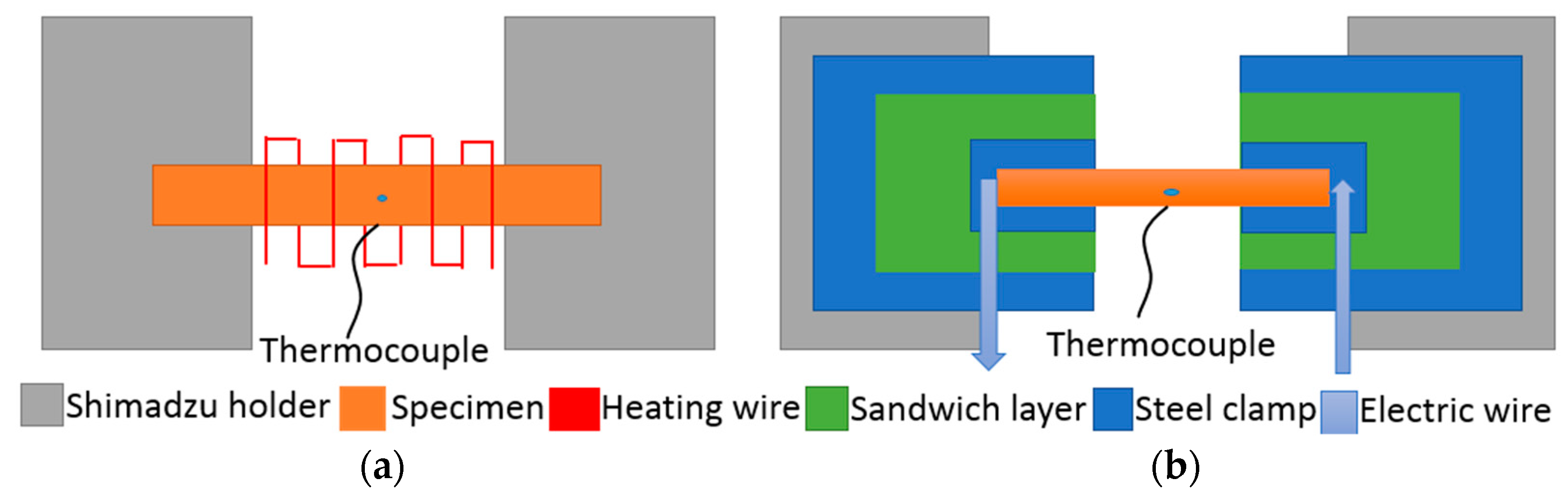
2.3. Resistance Heating

There are two main ways to heat the specimen in the SEM environment. One method is electric resistance wire heating, which transfers thermal energy to the specimen by the way of radiation or conduction as shown in Figure 1a. The other method shown in Figure 1b is Joule effect heating the specimen by passing the electric current directly through the specimen. Usually, using radiation heating method to heat the specimen, its temperature is difficult to exceed 700 °C because thermal electrons affect the secondary electron imaging in our SEM system of Shimadzu SS-550, which causes serious image quality degradation [6]. To the conduction heating, it is difficult to dynamically load and distinguish the load existed on the specimen due to the contact of the tested specimen with the heat source. Therefore, we designed a resistance heating unit to replace the thermal radiant heating module used in the Shimadzu SS-550 system, and employed a thermocouple, which was fixed in the center of the specimen, to real-time monitor the temperature of the specimen. Figure 1b shows the schematic of the heating unit.
Full-field deformation is an important parameter for investigating the high-temperature mechanical properties of alloy materials. In SEM in-situ high temperature experiment, the displacement caused by the external load under high temperature can be obtained by using digital image correlation (DIC) technique to analyze the speckle patterns on the surface of the materials. We selected Al2O3 nanoparticles as the speckle material because they show great resistance to high temperatures [7]. Figure 2a–d show the SEM speckle images under resistance heating and radiation heating, respectively. The results indicate that the speckle images gradually get fuzzy and saturation with the temperature increasing to 700 °C for radiation heating. However, the quality of the speckle image is still good when the resistance heating is even at 900 °C.

3. Results and Disccusion

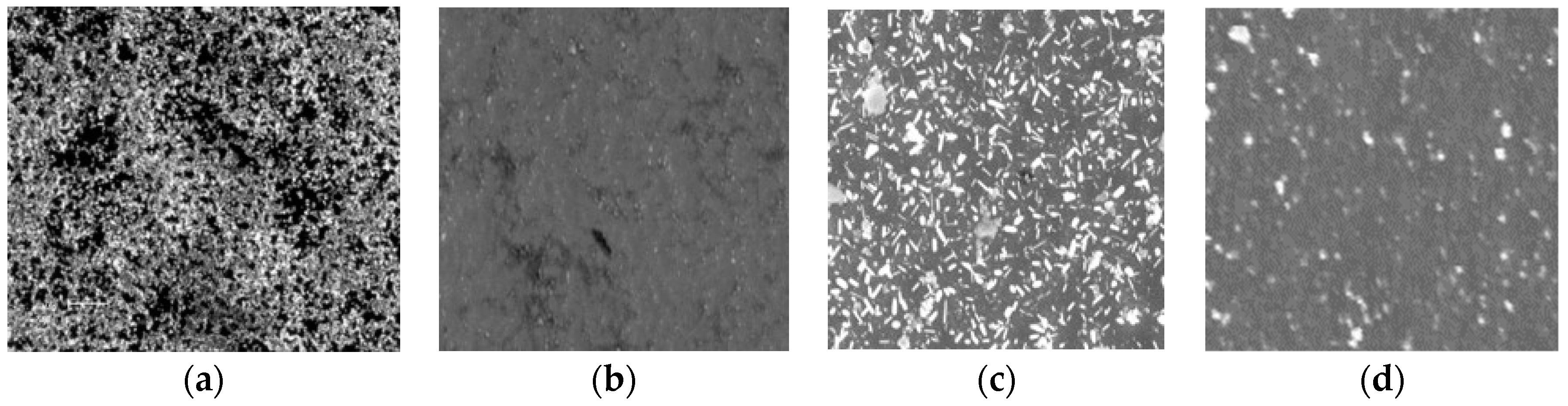
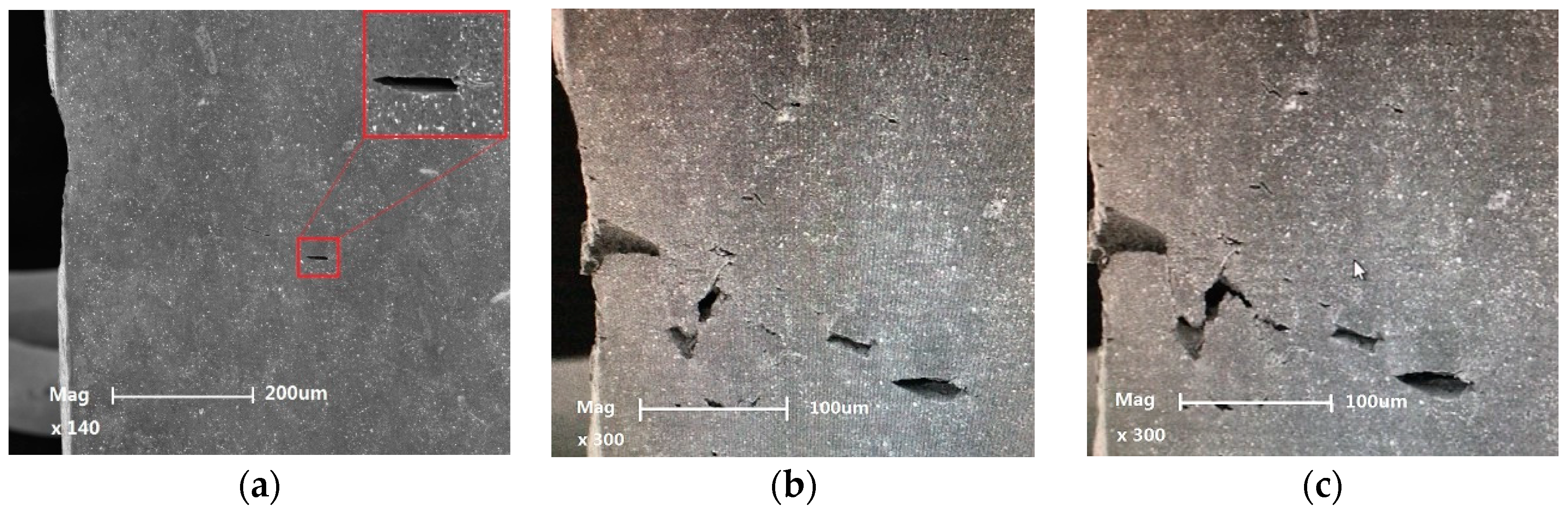
3.1. Observation of In Situ Failure Process of the Ni-Based Superalloy under High Temperature

The fracture mode of Ni-based superalloy was represented by three types: crystallographic plane facets fracture, mixed fracture mode and non-crystallographic fracture (I type fracture) from the low temperature to high temperature (>700 °C) [2]. This mainly relates to the actuation of the sliding surface and the behavior of dislocation activation. To observe the fracture process of Ni-based alloys at high temperature (>700 °C) in the real time, we performed the in-situ tensile experiment of Ni based superalloy with [001]/[011] orientation at 900 °C. Figure 3a–f showed the initiation and propagation of cracks during the stretching process. It was worth noting that Ni-based superalloy began to crack from the left of the section. This was mainly due to the presence of a certain amount of carbides around the location of the material, which led to the formation of a large number of microcracks or holes. When the external load was 70 N, the surface of the material had already undergone microcracks before yielding. The upper right corner of Figure 3a was a partial enlarged view. With the increase of the load, the number of microcracks gradually began to increase. Then, holes or microcracks would grow up and connect to each other under the action of the load. It was found that in the process of crack propagation, new holes were formed at the front of the main crack, as was shown in Figure 3e. Finally, the tested specimen failed due to voids connecting and the crack propagating through the specimen section. Figure 3f shows the fracture morphology of the specimen. It can be seen that the phenomenon of necking occurs near the middle of the specimen, which is consistent with the results of Wang et al. [8].

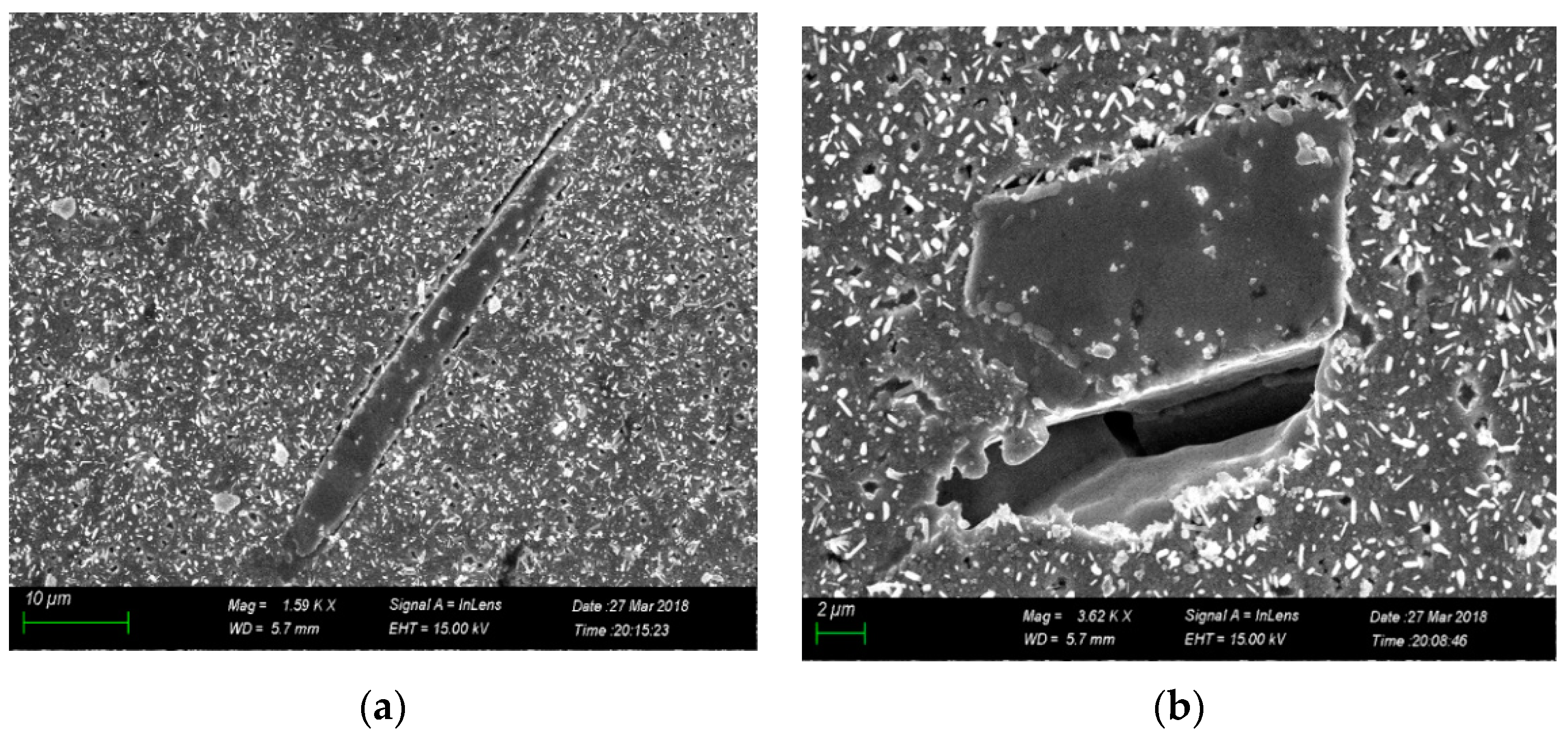
3.2. Failure Modes Caused by Inclusions

In general, the failure of Ni-based superalloy material originates from the sites of stress concentration. The main cause of stress concentration is the presence of defects in the material, including, MC, holes, precipitates phase and so on [9,10]. Figure 4a,b showed the two different morphology, rod and block shape, of carbide inclusions after tensile failure for PWA1483 Ni-based superalloy at 900 °C. We found that the carbides were integral and only debonded with the matrix. For the block-shape inclusions, holes can be found at the debonding interface, whereas for the rod-shape inclusions, only cracks were formed. By counting the inclusions on the surface of the specimens after failure, it was found that the number of cracks originating from inclusion debonding was far greater than the number of inclusions from which cracking occurred at 900 °C. However, at low temperatures, there was a competitive relationship between cracking and interface debonding of the carbide inclusion under the same level of the external load. Researchers found that the tendency of carbide cracking decreased and more carbide-matrix interface debonding were observed with increase temperature for CM 247 DS alloy [10]. This was consistent with our experimental results. The reasons were due to the different coefficients of thermal expansion and stress concentration caused by the external load. When the interfacial strength was below the stress concentration near interfaces, carbides-matrix debonding took place, and then, cracks or voids were generated. Considering the tensile test heated by the continuous electric currency, it existed the effect of local joule heating due to the different resistivity between the carbides and matrix, which caused non-uniform temperature [11]. It also increased the thermal mismatch between them, resulting in carbide-matrix interface debonding.

4. Conclusions

  • The resistance heating system was established in the in situ high-temperature fatigue experimental apparatus, which raised the in-situ testing temperature to more than 1000 °C. We successfully carried out an in-situ tensile test at 900 °C, which proved the effectiveness of the heating method.
  • It was found that at 900 °C, the initiation of cracks was mainly caused by debonding of inclusions, and holes would grow up and connect to each other. Finally, the tested specimen failed due to voids connecting and the crack propagating through the specimen section.

Acknowledgments

This work is financially supported by the National Natural Science Foundation of China (Grant No. 11632010, and 1147215).

References

  1. Reed, R.C. Introduction. In The Superalloys: Fundermentals and Applications; Cambridge University Press: Cambridge, UK, 2006. [Google Scholar]
  2. He, Z.; Zhang, Y.; Qiu, W.; Shi, H.J.; Gu, J. Temperature effect on the low cycle fatigue behavior of a directionally solidified nickel-base superalloy. Mater. Sci. Eng. A 2016, 676, 246–252. [Google Scholar] [CrossRef]
  3. Liu, J.; Tang, W.; Li, J. Deformation and fracture behaviors of K403 Ni-based superalloy at elevated temperatures. J. Alloys Compd. 2017, 699, 581–590. [Google Scholar] [CrossRef]
  4. Summers, W.D.; Alabort, E.; Kontis, P.; Hofmann, F.; Reed, R.C. In-situ high-temperature tensile testing of a polycrystalline nickel-based superalloy. Mater. High Temp. 2016, 33, 338–345. [Google Scholar] [CrossRef]
  5. Qiu, W.; He, Z.; Fan, Y.N.; Shi, H.J.; Gu, J. Effects of secondary orientation on crack closure behavior of nickel-based single crystal superalloys. Int. J. Fatigue 2016, 83, 335–343. [Google Scholar] [CrossRef]
  6. Liang, J.; Wang, Z.; Xie, H.; Li, X. In situ scanning electron microscopy-based high-temperature deformation measurement of nickel-based single crystal superalloy up to 800 °C. Opt. Lasers Eng. 2018, 108, 1–4. [Google Scholar] [CrossRef]
  7. De Roos, G.; Fluit, J.M.; De Wit, J.H.; Geus, J.W. The reaction of NiO and α-Al2O3 studied by Rutherford backscattering. Surf. Interface Anal. 1981, 3, 229–234. [Google Scholar] [CrossRef]
  8. Wang, J.; Guo, W.G.; Su, Y.; Zhou, P.; Yuan, K. Anomalous behaviors of a single-crystal Nickel-base superalloy over a wide range of temperatures and strain rates. Mech. Mater. 2016, 94, 79–90. [Google Scholar] [CrossRef]
  9. Texier, D.; Cormier, J.; Villechaise, P.; Stinville, J.C.; Torbet, C.J.; Pierret, S.; Pollock, T.M. Crack initiation sensitivity of wrought direct aged alloy 718 in the very high cycle fatigue regime: The role of non-metallic inclusions. Mater. Sci. Eng. A 2016, 678, 122–136. [Google Scholar] [CrossRef]
  10. Rai, R.K.; Sahu, J.K.; Jena, P.S.; Das, S.K.; Paulose, N.; Fernando, C.D. High temperature tensile deformation of a directionally solidified nickel base superalloy: Role of micro constituents. Mater. Sci. Eng. A 2017, 705, 189–195. [Google Scholar] [CrossRef]
  11. Zhang, X.; Li, H.; Zhan, M. Mechanism for the macro and micro behaviors of the Ni-based superalloy during electrically-assisted tension: Local Joule heating effect. J. Alloys Compd. 2018, 742, 480–489. [Google Scholar] [CrossRef]
Figure 1. Schematic diagrams for two kinds of heating units, (a) radiation heating unit; (b) resistance heating unit.
Proceedings 02 00507 g001
Figure 2. SEM speckle images at different temperatures. Radiation heating: (a) at ambient temperature 25 °C; (b) 700 °C. Resistance heating: (c) at ambient temperature 25 °C; (d) 900 °C.
Proceedings 02 00507 g002
Figure 3. In-situ failure process of Ni-based superalloy during loading at 900 °C. (a) microcracks of surface at 70 N; (be) holes and microcracks growing up and connection to each other under 105 N and (f) the fracture morphology of the specimen.
Proceedings 02 00507 g003aProceedings 02 00507 g003b
Figure 4. Two different morphology of carbide inclusion after tensile failure: (a) rod shape; (b) block shape.
Proceedings 02 00507 g004
Table 1. Chemical composition of the material (wt %).
ElementCrCoMoAlTiTaWCNi
Content12.29.01.93.64.15.03.80.07Balance
Publisher’s Note: MDPI stays neutral with regard to jurisdictional claims in published maps and institutional affiliations.

