Abstract
To minimize the costs of the current manufacturing of kitesurf hydrofoil wings, a workflow using a finite elements model was developed. By coupling a computational fluid dynamic (CFD) analysis with a structural finite element analysis (FEA), an optimization based on a genetic algorithm is implemented. The design space of the optimization is defined by the manufacturing processes. This enables the algorithm to find wing shapes which are not only suitable for the rider’s weight and preferred take-off speed but can also be produced directly on a universal mold surface. To reduce the amount of cut-off material and sustain the mechanical stresses, the output of the optimization contains the required number and orientation of all fiber layers within the reinforcement structure. This research shows that a single mold can produce different wing shapes to satisfy the needs of a wide range of customers.
1. Introduction
A hydrofoil refers to a single or a composition of wings that are attached to a watercraft under the water surface. At a certain velocity a hydrofoil generates enough lift to levitate the watercraft out of the water. In this state, known as “foiling”, the overall drag is reduced significantly and less power is needed to sustain speed. During recent years this technique has been adapted increasingly to wind powered water sports like kitesurfing. The generated lifting force of a hydrofoil equipped kiteboard is highly dependent on its wing shape, the flow velocity (riding speed) and the weight of the rider. Out of these parameters, specific use cases can be derived where the hydrofoil performs ideally. Thus, every change of the use case, such as the rider’s weight or preferred takeoff speed, makes a change of a hydrofoil’s wing shape necessary. High costs associated with the development and production of every specific wing shape make this problematic. Hydrofoil wings are made from carbon fiber reinforced plastic (CFRP) due to the high stresses they must sustain. CFRP manufacturing requires individual molds and stacking sequences of CFRP layers for every individual wing shape. To supply every kite surfer with a hydrofoil tailored to weight and riding style, a drastic reduction of costs in development and manufacturing, especially for molding and CFRP stacking sequence, is necessary. To achieve these goals, a concept based on a scalable workflow for the development of hydrofoil wings and a universal open mold design for manufacturing is established. A parametrized finite element (FE) model is used to optimize wing shapes and according CFRP stacking sequences for specific use cases. The design space is constrained by the requirement that all possible shapes must be manufacturable on the same universal open mold design. It is the aim of this paper to investigate the technical profitability of the concept in a parameter study and identify possible use cases within the given limitations of design.
2. Parametrized Numerical Model
2.1. General Simulation Approach
The workflow for the optimization of the hydrofoil wing consists of three steps:
- Step 1: Computational fluid dynamic (CFD) analysis and optimization of a basic wing shape, used to derive a universal mold design
- Step 2: Parameter study; multiple loops of CFD analyses based on the optimized basic wing shape with scaled geometrical design variables, manufacturable on universal mold
- Step 3: Static structural analysis and optimization of the wings’ CFRP stacking sequences
The parameter study in Step 2 enables an investigation of the technical profitability of the workflow’s concept to manufacture a universal mold that allows to manufacture multiple varying wing shapes customized on kite surfers’ individual and use cases. Possible wing shapes based on scaled design variables of an optimized basic wing were analyzed. Results of the parameter study are:
- the range of feasible use cases of wings manufactured on the universal mold, and
- the impact of the geometrical design variables on the generated lift depending on given flow velocities.
2.2. CFD and Shape Optimization
The entire geometry of the hydrofoil’s wing shape was defined in a parametric model. The National Advisory Committee for Aeronautics (NACA) four-digit number airfoil system describes the cross sections of the wing shape at tip and root (see Figure 1). The NACA four-digit number characterizes the upper and lower surface of the cross section with three geometric variables, the location of the maximum camber P, the degree of the maximum camber M and the thickness of the wing T [1] (shown in Figure 2).
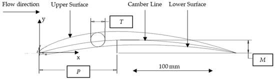
Figure 1.
Wing profile according to NACA four-digit number with three parameters.
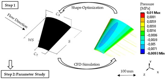
Figure 2.
Visualization of step 1 in the workflow: Optimization of the wing shape driven by a desired lift at a certain velocity.
With these parameters, the camber line and the thickness distribution of a wing profile can be displayed as continuous functions and , where x is referring to the cartesian coordinate system shown in Figure 1. Those two functions are then used to generate the spline’s X and Y coordinates for the upper and lower surface of the wing cross section [2]. To fully describe the three-dimensional shape of the wing, four additional geometric variables were added. The span of the wing S, the chord length at the wing-root CR and the wing tip CT, and the sweep of the wing WS. The final three-dimensional wing is shown in Figure 2.
For the FE calculations, the resulting wing shapes were meshed in a routine. To select a meshing method which produces satisfying results while keeping the overall number of finite elements low, the one-equation Spalart-Allmaras turbulence model was chosen. This model has low demands on the mesh regarding the recommended wall thickness [3] while it is still able to generate robust solutions. It is commonly used in the aviation industry [4]. A comparison with the more precise two-equation k-ε turbulence model shows less than 5 % deviation of the calculated lift, which is an acceptable inaccuracy.
For the optimization of the basic wing shape in Step 1 of the workflow, all geometric variables (Figure 1 and Figure 2) serve as design variables. The first objective function of the optimization is to achieve the lift FL at a certain flow velocity uL. To assure that the wing not only generates sufficient lift but is also hydrodynamically efficient, the minimization of the lift to drag ratio E is introduced as a second objective function. The optimization starts with a population of 60 different and randomized wing designs and finds the best wing shape after six iterations, leading to over 360 simulated wing shapes. All optimization parameters and results of the example used in this study are listed in Table 1. For the ongoing steps of the workflow, the lower surface of this basic wing shape serves as the shape of the universal mold.

Table 1.
Computational fluid dynamic (CFD) optimization parameters and results.
2.3. Parameter Study CFD Analyses of Scaled Wing Shapes Manufactured on Universal Mold
In Step 2, the parameter study is carried out on scaled wing shapes based on the basic wing shape and universal mold, respectively. The geometry variables CR, CT and S are scaled down simultaneously in steps of 2.5 % from their values of the basic wing shape. The meaning of scaling down the wing is visualized in Figure 3.
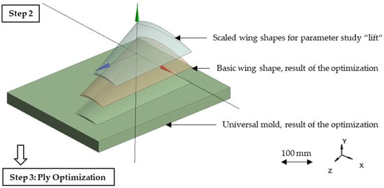
Figure 3.
Visualization of Step 2 showing a universal mold, a basic wing shape (Step 1) and an example of a scaled wing shape manufacturable on the universal mold.
The CFD analyses show the range of lift at given flow velocities that can be served with manufacturable wing shape designs. As the lower wing surface is scaled down, too, this leads to a certain deviation of the simulated wing shapes from actually molded wing shapes. A slight deviation of the effectively achievable lift and drag values is expected. To keep this deviation low, a maximal scaling to 90 % of the basic wing shape is allowed. The results of the parameter study are summarized in Figure 4.
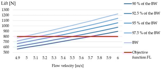
Figure 4.
Results of CFD parameter study on scaled wing shapes based on the basic wing shape (BW): Generated lift of scaled wing shapes within the given parameter space in a range of 4.9–6.0 m/s flow velocity.
2.4. Static Structural Analysis and Optimization of the Stacking Sequence
In the final third step of the workflow the structural optimization of the hydrofoil wing’s CFRP stacking sequence is performed on a desired wing shape (Figure 5). This wing shape can be the original basic wing shape or a scaled wing shape which is manufacturable on the universal mold. The stacking sequence of the carbon fibers will be placed with an automated dry fiber placement (DFP) machine to reduce cutting waste to a minimum. A fiber spreading process integrated in the DFP machine allows spreading carbon fibers extensively, so that roving grammages as low as 50 g/m2 can be achieved. The resulting fiber lay-up will be cured with vacuum infused epoxy resin. As a load case the resulting pressure field at a desired riding speed (flow velocity), determined in the CFD analysis, affecting the wing is introduced. The wing’s structure consists of the upper and lower wing surface and two box spars in between of these [5,6]. All knots at the root of the wing serve as fixed support. The order of ply orientations is pre-specified with fiber orientation angles of (0°/90°/+45°/−45°), while the X-axis is defined as the 0° direction and Z-axis as the 90° direction (Figure 5). This order is applied on the wing’s top surface as well as in mirrored order on the bottom surface to create a symmetrical stacking sequence. Assumed material properties for a CFRP-layer with a grammage of 100 g/m2 are listed in Table 2.
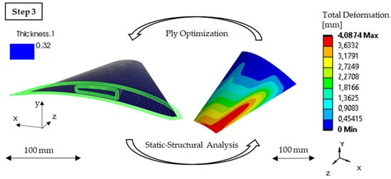
Figure 5.
Visualization of Step 3 showing the optimization process with the aim to reduce the overall amount of material while maintaining defined constrains (see Table 3).
Table 2.
Material properties for a single carbon fiber reinforced plastic (CFRP) layer.
The numbers of plies for each orientation angle serve as design variables. The first objective function is to minimize the number of plies. A second objective function claims to minimize the four failure criteria of Hashin under the given load case [7]. These failure criteria consist of tension in fiber direction Hft, pressure in fiber direction Hfp, tension orthogonal to fiber direction Hmt and pressure orthogonal to fiber direction Hmp. If the result of the failure criteria reaches the value of 1, the failure of the component is assumed. The maximal deformation of the wing is constrained to 3 mm. Table 3 summarizes the optimization parameters and shows the result of the optimization.
Table 3.
Optimization of the stacking sequence.
3. Discussion
As shown in Figure 4, it is possible to manufacture different wing shapes with a single universal mold concept that covers a large range of use cases and fulfills all objective functions (see Table 1 and Table 3). Depending on the desired take off speed, hydrofoil wings for riders with a system weight between approximately 55 and 120 kg can be tailored. A change of the wingspan has a much higher influence on the achievable lift of a wing than the thickness of the wing profile. Decoupling the wingspan’s scaling factor from the scaling factor of the wing profile would lead to an even broader range of realizable take off speeds and rider weights. Limiting the simulation workflow is the scaling of wing shapes as described in Section 2.3. The larger the deviation of the simulated lower wing surface’s geometry from the effectively manufacturable lower wing surfaces, the less accurate the simulated lift and drag values will be. A follow-up examination concluded that the simulated 90%-scale model showed about 2.5 % more lift and drag than it would provide with its actual lower wing surface from the universal mold. Thus, the lift and drag ratio remains equal. Including the mold surface in the parametric shape modelling of the hydrofoil wing would solve this inaccuracy. The low Hashin criteria (see Table 3) marks the high safety factor of the wing. Exploiting the anisotropic material properties of CFRP more extensively could reduce the weight of the wings even further. It would be expedient to adapt the fiber orientations of the plies more closely along the predominant directions of main tensions [8,9] and finally optimize the stacking order of the single plies.
4. Outlook and Summary
The established simulation workflow proved to be capable of providing a broad range of kite surfers with a tailored hydrofoil wing while keeping manufacturing efforts low. To increase the precision of the CFD-analyses, the parametric model should include the surface of the universal mold design to scaled wing designs. Samples out of the entire range of use cases must be manufactured and undergo flow channel testing. There the occurring values of lift and drag can be measured and compared with the simulated results. As the predominant component in kite surfing is the athlete him- or herself, conducting field tests is necessary to evaluate the performance of the wing shapes generated with this workflow.
Conflicts of Interest
The author declares no conflicts of interests.
References
- Schlichting, H.; Truckenbrodt, E. Aerodynamik des Flugzeuges, 2nd ed.; Springer: Berlin/Heidelberg, Germany, 2001; pp. 353–365. [Google Scholar]
- Cummings, R.; Mason, W.; Morton, S.; McDaniel, D. Geometry for Aerodynamicists. In Applied Computational Aerodynamics: A Modern Engineering Approach, 1st ed.; Cambridge University Press: Cambridge, UK, 2018; pp. 353–365. [Google Scholar]
- Lecture 7: Turbulence Modeling. Available online: https://www.academia.edu/36090206/Lecture_7_Turbulence_Modeling_Introduction_to_ANSYS_Fluent (accessed on 1 November 2019).
- Allmaras, S.R.; Johnson, F.T.; Spalart, P.R. Modifications and Clarifications for the Implementation of the Spalart-Allmaras Turbulence Model. In Proceedings of the Seventh International Conference on Computational Fluid Dynamics (ICCFD7), Big Island, HI, USA, 9–13 July 2012. ICCFD7-1902. [Google Scholar]
- Stanford, B.K.; Dunning, P.D. Optimal Topology of Aircraft Rib and Spar Structures Under Aerolastic Loads. J. Aircr. 2014, 52, 1–23. [Google Scholar] [CrossRef]
- Ajith, V.S.; Paramasivam, R.; Vidhya, K. Study of Optimal Design of Spar Beam for the Wing of an Aircraft. IJEDR 2017, 5, 179–193. [Google Scholar]
- Progressive Damage of Fiber-Reinforced Composite in ANSYS V15.0. Available online: https://caeai.com/sites/default/files/CAEA_v15_ANSYS_Composite_Damage.pdf (accessed on 1 November 2019).
- Spickenheuer, A. Zur Fertigungsgerechten Auslegung von Faser-Kunststoff-Verbundbauteilen für den Extremen Leichtbau auf Basis des Variabelaxialen Fadenablageverfahrens Tailored Fiber Placement. Ph.D. Thesis, Technische Universität Dresden, Dresden, Germany, 2014. [Google Scholar]
- Fleischmann, M.; Ehemann, C.; Kaufmann, J.; Cebulla, H. Optimization of Lightweight Axles for an Innovative Carving Skateboard Based on Carbon Fiber Placement. Proceedings 2018, 2, 253. [Google Scholar] [CrossRef]
Publisher’s Note: MDPI stays neutral with regard to jurisdictional claims in published maps and institutional affiliations. |
© 2020 by the authors. Licensee MDPI, Basel, Switzerland. This article is an open access article distributed under the terms and conditions of the Creative Commons Attribution (CC BY) license (https://creativecommons.org/licenses/by/4.0/).