1. Introduction
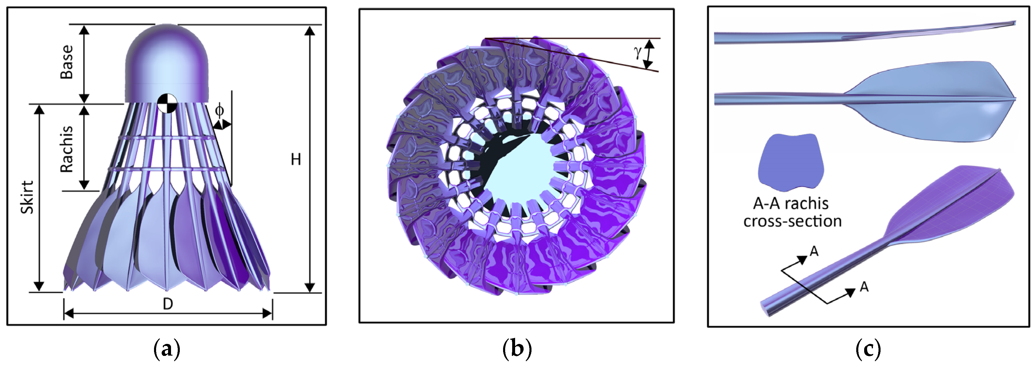
Feather shuttlecocks, as porous conical bluff bodies, are aerodynamically unique sports projectiles. Incomparable in form and mass, and associated with high flight speeds and high spin, shuttlecocks exhibit the largest inflight deceleration of any sports projectile. These traditional shuttlecocks are constructed using 16 waterfowl feathers that have been trimmed to create a specific vane shape. The shaped feathers are inserted into a predrilled fabric covered cork base and aligned to create a conical skirt of overlapping feather vanes. Feather shuttlecocks are considered aerodynamically superior to synthetic polymer variations, despite the extensive efforts of manufacturers to create a synthetic shuttle with comparable performance. As such, the aerodynamic behavior of these projectiles has proved of interest to researchers. However, published experimental and wind tunnel investigations of shuttlecocks present values of drag coefficients that vary widely [
1], ranging from 0.48 <
Cd < 0.74. Some variance may be expected for a natural product, however many of these investigations use different designs of experimental sting to support the shuttlecock. Some designs allow for free rotation of the shuttlecock about the longitudinal axis, whilst others hold the shuttlecock statically fixed. Differing effects of rotation have been demonstrated [
2,
3]. Cohen et al. [
2] reported a lower average drag coefficient (
Cd ~ 0.68) for a freely rotating shuttlecock, than when statically fixed (
Cd ~ 0.74). In contrast, Kitta et al. [
3] reported a marginally higher average drag coefficient (
Cd ~ 0.61) for freely rotating conditions compared to statically fixed (
Cd ~ 0.56). It is known that shuttlecocks experience a reduction in skirt diameter as the Reynolds number Re increases [
3,
4]. However, it has been shown that there is no significant difference in skirt diameter, between rotating and static conditions; until
Re > 2.1 × 10
5 when centrifugal forces acting on a spinning shuttlecock caused an abrupt expansion of the skirt [
3,
4]. There is no doubt that the variation in drag between rotating and static conditions may be considered slight, however this is still an important aspect of performance to understand. It is believed that reported differences in behavior with rotation may be attributable to the aerodynamic sting. Traditionally inserted into the aft of the shuttlecock base, air movement through this region is known to have a significant influence on aerodynamic performance [
1,
4,
5]. Concerns have been raised about the insertion of such experimental equipment into a region that has been shown to have significant influence on the measured performance of the shuttlecock [
1]. Computational fluid dynamics (CFD) do not require use of an experimental sting. With careful and robust application, CFD has been shown to have great potential for the prediction and understanding of the aerodynamic performance of shuttlecocks [
1]. All previous CFD studies [
1,
5,
6,
7,
8] however have considered the projectile as being stationary. This paper presents a numerical comparison between a rotating and statically fixed geometrically realistic feather shuttlecock at high Re. Scale resolving turbulence models are applied to study the formation and structure of vortices.
3. Results & Discussion
Simulations were conducted over the range of Reynolds number (90,000 <
Re < 271,000) with and without rotation. Time-averaged force coefficient values are presented in
Figure 2a, in comparison to values obtained from wind tunnel investigation [
2,
3]. These values were obtained by averaging instantaneous force values over the normalized period 20 =
TsU/
D. Drag coefficient can be seen to be largely independent of
Re. The static shuttlecock had an average time-averaged drag coefficient of
Cd = 0.76. When rotational motion was applied to the shuttlecock drag coefficient reduced to
Cd = 0.73, a 4% reduction was found (experimental studies reported ~8% difference [
2,
3]). It should be noted that the shuttlecock feathers are rigid in this simulation, therefore
D is constant, however as stated, no significant difference in
D between rotating and static conditions was observed in experiment [
3,
4] until
Re > 2.1 × 10
5. Pressure drag was found to account for 95% of measured
Cd for both conditions, and the contribution of each shuttle component was found independent of
Re (~13.5% base, ~22% rachis, ~56.5% vanes, ~7.4% twine).
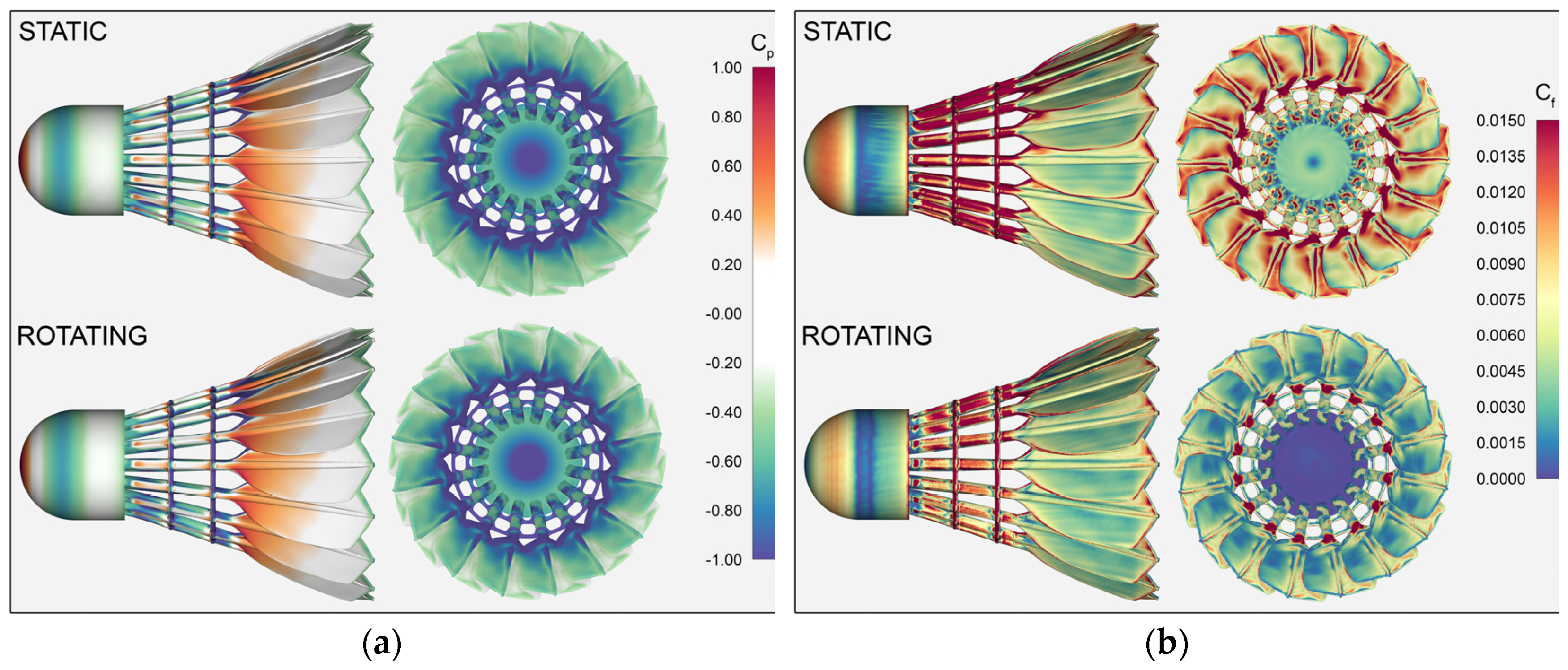
Applying rotation to the shuttlecock increased drag on the shuttlecock base by 1.1%, this increase is attributable to a decrease in pressure coefficient
Cp acting on the aft of the base,
Cp = −1.15 static,
Cp = −1.46 rotating, as can be seen in
Figure 2b at
x = 0 and
Figure 3a. As
Cd and statistical surface values were found to be independent of
Re, all results plotted herein are for
Re = 2.7 × 10
5. Plots of skin friction coefficient
Cf are shown in
Figure 3b. It can be seen that for the rotating condition, a lower
Cf is evident on the domed portion of the base, followed by a clear band of flow separation and subsequent reattachment. A significant difference in
Cf is visible on the aft of the base between the static and rotating conditions. When the shuttlecock is rotating,
Cf values indicate a completely separated internal flow.
In contrast to the base, individual component drag is seen to reduce on the vanes, rachis, and twine, by approximately 5% when a rotational condition is applied. This again can be seen in
Figure 2b, however the difference is too subtle to be clear in
Figure 3a. Plots of skin friction coefficient
Cf again however reveal a difference in the movement of flow across the rachis, and in particular on the vane surfaces internal to the shuttlecock. Flow movement across the internal vane surfaces appears to be separated when the shuttlecock is rotating. A lower value of
Cf can also be seen between adjacent vane surfaces, suggesting a lower velocity passage of flow between the vanes.
The mean velocity flow field is shown in
Figure 4, revealing the movement of flow internal to the shuttlecock, while clear differences in flow structure as indicated by plots of
Cf are confirmed. A significant region of stagnant flow is visible behind the shuttlecock base for the rotating condition. Adjacent to this stagnant region, it can be seen that flow enters the shuttlecock between the base aft and the first twine band at a reduced velocity. A significant region of accelerated flow passing between the second band of twine and leading edge of the vane is still evident. Within this region, the pressure coefficient on the leading edge of the vane internal surface reduces to as low as
Cp = −3.3.
For the static shuttlecock a thin region of high velocity flow is seen adjacent to the internal vane surface. This originates from flow external to the shuttlecock entering and accelerating between the adjacent vane surfaces, as indicated in
Figure 3b. As a result, the separated circulating flow behind the vanes is offset from the vane surface. In contrast when the shuttlecock is rotating, this passage of fluid between adjacent vanes is no longer evident and a stronger region of circulating flow is seen to form behind the vane surface. The shape of the flow at the trailing edge of the vane is also seen to change, suggesting that the vortex roll up and separation in this region is altered.
Figure 5a shows center plane contours of instantaneous vorticity in the applicate (
z) direction. It is clear the formation of the trailing edge vortices is indeed influenced by the rotation of the shuttlecock. The transient structures that from at this edge appear to extend less distance behind the shuttle and to breakdown quickly. Internally there appears to be little difference in the formation of the transient smaller scale structures, attributable to passage of flow through the shuttlecock rachis region.
The visualization of wake structures using the Q-criterion method [
10] confirm the differences in flow that exist at the shuttlecock vane trailing edges, as seen in
Figure 5b and
Figure 6. Thin streamwise cores can be observed to roll up between adjacent vane surfaces when the shuttlecock is statically fixed. These can be seen to extend as distinct features a short distance behind the trailing edge before they begin to merge and roll up into larger structures. When the shuttlecock is rotating, these thin streamwise core structures are not observed to form, instead vortices are seen to originate across the length of the trailing edge at regular intervals from the internal vane surface. These quickly begin to merge into larger structures, as was suggested by the contours of instantaneous vorticity,
Figure 5a. However, no other significant differences in vortical structures are observed within the large wake that extends behind the shuttlecock. Other differences can be seen in the formation of vortices around the shuttle between the static and rotating conditions. Small streamwise vortices are seen to roll up and traverse across the external surface of the vane when the shuttlecock is rotating. Whilst when the shuttlecock is statically fixed, vortices can be seen to spiral around the shuttlecock cylindrical section of the base, as swirling around this section is induced by the flow being drawn into the shuttlecock rachis region.


