Proceeding Paper

Adjusting a Momentum-Based Golf Clubhead-Ball Impact Model to Improve Accuracy †

1
Systems Design Engineering, University of Waterloo, 200 University Ave. W, Waterloo, ON N2L 3G1, Canada
2
Ping Inc., 2200 W. Peoria Ave., Phoenix, AZ 85029, USA
*
Author to whom correspondence should be addressed.
Presented at the 13th conference of the International Sports Engineering Association, Online, 22–26 June 2020.
Proceedings 2020, 49(1), 47; https://doi.org/10.3390/proceedings2020049047
Published: 15 June 2020

Abstract

:
In this paper, two simple and physically meaningful adjustments were made to a momentum-based clubhead-ball impact model to predict golf ball launch conditions with better accuracy. These adjustments were motivated by two shortcomings of the momentum-based impact model, namely the absence of shaft effects and golf ball deformation. Kinematic data from a golf impact motion capture experiment was used to empirically determine the parameter adjustments that minimized the ball speed and spin errors. It was found that the original model’s ball speed deficiency could be corrected by adding less than 3 g to the clubhead mass, and the amount of added mass correlated with the mass of the shaft. Additionally, the original model’s backspin and sidespin errors were significantly reduced by making a slight adjustment to the golf ball’s center of mass position relative to the impact location. Specifically, moving the golf ball center of mass approximately 0.5 mm downward and 0.07 mm towards the heel reduced the mean backspin and sidespin errors by approximately 85% each.

1. Introduction

A golf clubhead-ball impact model can be a useful tool for investigating new clubhead designs. Finite-element and momentum-based impact models are among the most commonly used methods for predicting a golf ball’s initial linear and angular velocity [1,2,3,4]. Compared to finite-element methods, momentum-based impact models are far less taxing computationally and thus enable fast clubhead design optimization [2,3]. However, due to simplifying assumptions in deriving momentum-based models, there exist significant discrepancies between the predicted and experimental golf ball launch conditions, as demonstrated in this study.
Two assumptions that affect the accuracy of the momentum-based impact models are neglecting the deformation of the golf ball during the impact and the influence of the golf shaft on the impact dynamics [5]. The purpose of this study was to account for the aforementioned factors by making two simple and physically meaningful adjustments to the conventional momentum-based impact model. The first involves making a slight adjustment to the center of mass of the golf ball to account for golf ball deformation, while the second involves adding mass to the clubhead in proportion to the shaft mass. Together, these two modifications were shown to greatly reduce the error between the predicted and measured golf ball launch conditions. Experimental data from golf impact motion capture experiments were used to characterize the modifications and provide general rules of thumb for improving the accuracy of momentum-based impact models used in golf research.

2. Materials and Methods

2.1. Experimental Data

All experimental data were collected by a golf equipment manufacturer and shared with the University of Waterloo to support the development of the impact model. A golf swing motion capture experiment was conducted using three drivers having the same clubhead but three different stiff-rated shafts. The shafts had a length of 1.105 m, and masses 74.5, 60.3, 70.9 g for Shafts A, B, and C, respectively. Shafts B and C were of the same make and model, but a strip of lead tape was placed on Shaft C from 350 to 640 mm from the tip to increase its mass. Twenty golfers participated in the experiment and performed 10 swings using each driver. The clubhead kinematics just before the moment of impact was recorded and used in the impact model equations (see Section 2.2.1). A launch monitor (GCQuad, Foresight Sports, San Diego, CA, USA) was used to measure the golf ball’s launch conditions. The University of Waterloo gave ethics clearance to perform secondary analysis on the golf swing motion capture data.
The physical properties of the clubhead and other parameters used for the impact model are provided in Table 1. Further details regarding the motion capture system (Nexus v2.5, Vicon Motion Systems, UK) and the measurement of the clubhead properties are available in [6]. The origin of the impact coordinate frame, I , coincides with the point of contact, and its x-axis is perpendicular to the clubface at the contact point.

2.2. Momentum-Based Clubhead-Ball Impact Model

This section reviews the momentum-based clubhead-ball impact model presented in [1]. In contrast to the ellipsoidal clubface surface used in [1], this model uses a toroidal surface that allows constant bulge and roll curvatures.

2.2.1. Equations of Impulse and Momentum

Figure 1 shows the free body diagram of the clubhead contacting the golf ball. It should be noted that the wrench (i.e., force and torque) applied from the driver shaft on the clubhead has not been considered in the free body diagram, which is one of the simplifying assumptions in this model.
Applying the principle of impulse and momentum to the clubhead yields,
m c v c t 1 P = m c v c t 2
I c ω c t 1 r i m p × P = I c ω c t 2
where P is the impulse applied to the golf ball from the clubhead. Also, v c and ω c are, respectively, the linear and angular velocity of the center of mass of the clubhead. Similarly, for the golf ball we have:
m b v b t 1 + P = m b v b t 2
I b ω b t 1 + r b × P = I b ω b t 2
where v b and ω b are, respectively, the linear and angular velocity of the center of mass of the golf ball. Here and throughout this report, t 1 and t 2 , respectively, refer to the time just before and after the impact.
To take the energy loss into account, the relationship between the magnitude of the translational velocity of the contact point of the clubhead, and the ball in the direction perpendicular to the contact surface is written in terms of the coefficient of restitution, i.e., e , as:
e = v i m p , c t 2 v i m p , b t 2 x ^ i m p v i m p , c t 1 v i m p , b t 1 x ^ i m p
where x ^ i m p is the unit vector normal to the clubface, and v i m p , c and v i m p , b are, respectively, the translational velocity of the contact point of the clubhead and the ball, which are obtained as:
v i m p , c = v c + ω c × r i m p
v i m p , b = v b + ω b × r b
In this model, it has been assumed that the friction between the clubhead and ball is high enough that the ball does not slip onto the clubface. Therefore, the relative velocity of the clubhead and the ball are assumed to be zero in the plane tangent to the contact surface, which yields the following equations:
v i m p , c t 2 v i m p , b t 2 y ^ i m p = 0
v i m p , c t 2 v i m p , b t 2 z ^ i m p = 0
Equations (1)–(5), (8) and (9) constitute a set of 15 linear equations in terms of 15 unknowns, for which an analytical solution can be found for P , v c ( t 2 ) , ω c ( t 2 ) , v b ( t 2 ) , and ω b ( t 2 ) .

2.2.2. Clubhead Face Geometry

To calculate the impact coordinate frame, { I } , at different impact locations on the clubhead, its surface is modeled as that of a torus. Referring to Figure 2, the x-component of the impact location with respect to the reference frame of the torus can be obtained from the y and z components of the impact location as:
x = 2 R r 2 y 2 + R 2 + r 2 y 2 z 2
where R and r are, respectively, the bulge and roll values of the torus. It can be shown that the components of the three-unit vectors for the impact reference frame are:
X ^ i m p = 1 R x 2 + z 2 x y 1 R x 2 + z 2 z T 2 1 R x 2 + z 2 2 + 1
Z ^ i m p = z 0 x T x 2 + z 2
Y ^ i m p = Z ^ i m p × X ^ i m p

2.2.3. Prediction Errors for Nominal Parameters

The accuracy of the presented impact model was evaluated by comparing the results of the simulation with the experimental results. For the nominal values of the clubhead and golf ball properties given in Table 1, the mean square errors and standard deviation of the errors are given in Table 2. As can be seen, the model predicts the launch condition of the golf ball with considerable error, especially for angular velocity, when nominal values of the properties are used. It is apparent that a more accurate model is needed.

2.3. Impact Model Augmentation

The momentum-based impact model was augmented using simple and physically meaningful modifications to the impact model parameters. An optimization-based approach was used to minimize the ball launch condition errors by tuning the parameters given in Table 1. The cost function J is written as:
J = i = 1 n W v S i m , i v E x p , i 2 + ω S i m , i ω E x p , i 2
where v S i m , i and v E x p , i are the linear velocities of the ball from the model and experimental data for each impact i . Similarly, ω S i m , i and ω E x p , i denote the angular velocities of the ball from the model and experimental data. Furthermore, n is the number of experimental data points, and W is the weight given to the error for linear velocity. When W 0 , the optimizer minimizes the angular velocity error, and when W , the optimizer minimizes the linear velocity.
As the first step, the effect of each parameter on the linear and angular velocity of the golf ball was evaluated by performing a sensitivity analysis. It was observed that the mass of the clubhead affected the linear velocity without considerably altering the angular velocity. On the other hand, the location of the center of mass of the ball with respect to the impact location, I r b , had a great influence on the angular velocity, while having a small impact on linear velocity.
By alternating between optimizing the parameters with high impact on linear velocity ( W = ) and high impact on angular velocity ( W = 0 ), a multi-stage gradient-descent-based optimization was performed to minimize both linear and angular velocity prediction errors.

3. Results and Discussion

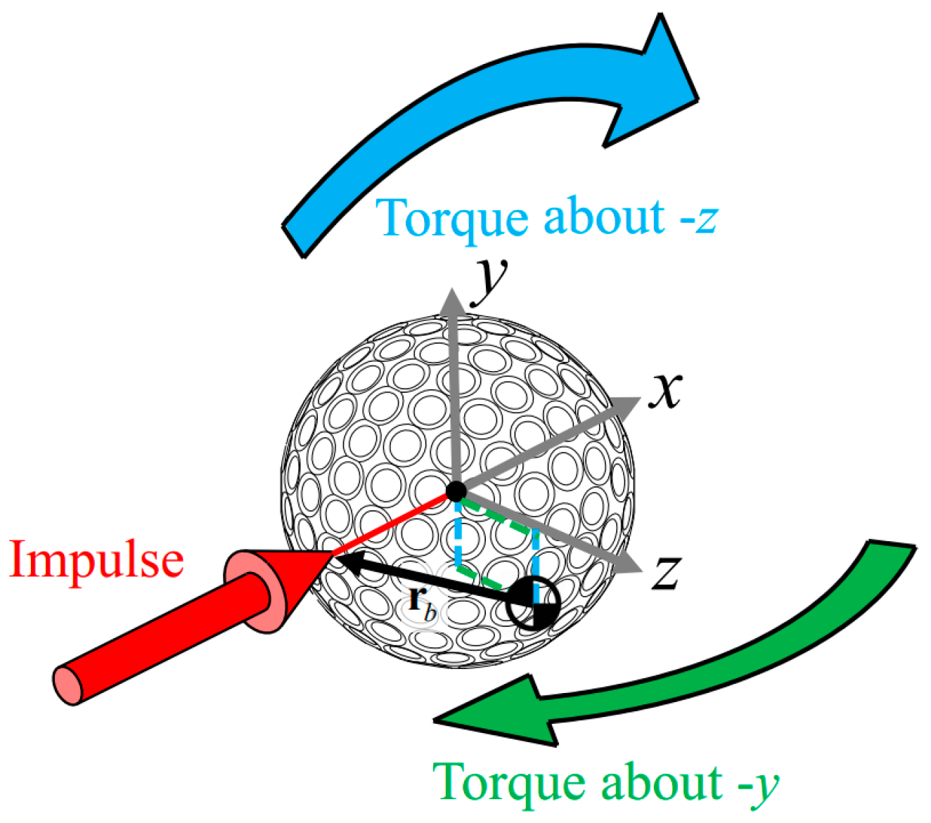
The results of the launch condition errors after the optimization are shown in Table 3. Comparing Table 3 and Table 2, one can observe that the mean value of the prediction errors for both linear and angular velocity was considerably reduced. Table 4 shows the changes made to the selected parameters after optimization. It could be observed that the difference between the optimal values and the original values are very small. Furthermore, as shown in Figure 3, the added mass correlated with the mass of the corresponding shaft. It should also be noted that the change in the position of the center of mass of the golf ball created a moment arm for the impact impulse, which, as illustrated in Figure 4, helped to reduce the over-estimated predictions of the backspin and sidespin.

4. Conclusions

It was observed that the predicted launch condition for a golf ball using an impulse-momentum model did not match the experimental results, especially for the angular velocity. By selecting the mass of the clubhead and the position of the center of mass of the golf ball with respect to the impact location as optimization variables, the prediction errors were considerably reduced with very small changes to the original parameters (less than 3 g for the clubhead mass and about 0.5 mm for the position of the center of mass of the golf ball). Furthermore, the added mass was shown to be directly related to the mass of the shaft.

Conflicts of Interest

The authors declare that they have no conflict of interest.

References

  1. Petersen, W.; McPhee, J. Comparison of impulse-momentum and finite element models for impact between golf ball and clubhead. In Science and Golf V: Proceedings of the World Scientific Congress of Golf, Phoenix; Energy in Motion, Inc.: Mesa, AZ, USA, 2008. [Google Scholar]
  2. McNally, W.; Balzerson, D.; Wilson, D.; McPhee, J. Effect of Clubhead Inertial Properties and Driver Face Geometry on Golf ball Trajectories. Procedia Eng. 2016, 147, 407–412. [Google Scholar] [CrossRef]
  3. Winfield, D.; Tan, T. Optimization of clubhead loft and swing elevation angles for maximum distance of a golf drive. Comput. Struct. 1994, 53, 19–25. [Google Scholar] [CrossRef]
  4. Tanaka, K.; Teranishi, Y.; Ujihashi, S. Finite element modelling and simulations for golf impact. Proc. Inst. Mech. Eng. Part P: J. Sports Eng. Technol. 2012, 227, 20–30. [Google Scholar] [CrossRef]
  5. McNally, W.; McPhee, J.; Henrikson, E. The golf shaft’s influence on clubhead-ball impact dynamics. Proceedings 2018, 2, 245. [Google Scholar]
  6. McNally, W.; Henrikson, E.; McPhee, J. A continuous analytical shaft model for fast dynamic simulation of the golf swing. Sports Eng. 2019, 22, 20. [Google Scholar] [CrossRef]
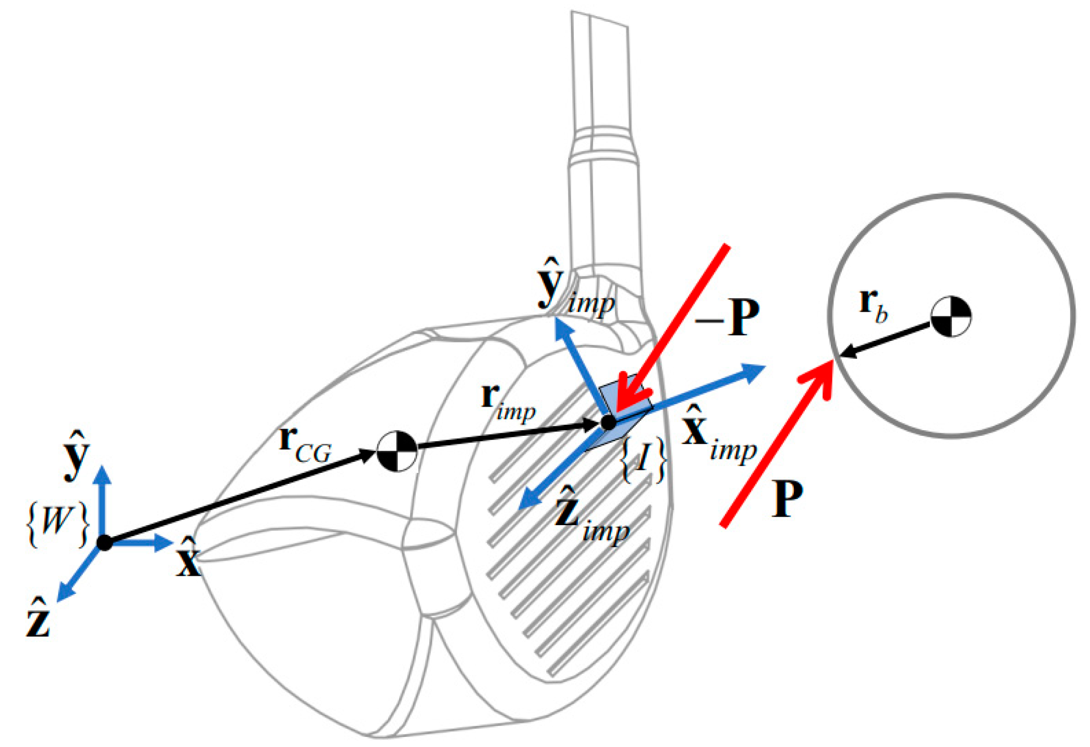
Figure 1. Free body diagram of the impact between the clubhead and the ball.
Proceedings 49 00047 g001
Figure 2. Torus representing the clubface geometry.
Proceedings 49 00047 g002
Figure 3. The relationship between the mass of the shafts and the added mass to the clubhead.
Proceedings 49 00047 g003
Figure 4. Change of Center of Mass of the golf ball and the resulting moments from the normal force (the figure is not drawn to scale).
Proceedings 49 00047 g004
Table 1. Nominal (measured) properties of the clubhead and golf ball. The reference frames used are provided in Figure 1.
ParameterValueDescription
m c 204Mass of the clubhead (g).
r C o F C / C o F [ 42.3 2.9 1 ] Position of the center of mass (C) of the clubhead with reference to Center of Face (CoF) expressed in CoF reference frame (mm).
I C C 2843 733 530.2 733 5679 0.5 530.2 0.5 4085 Inertia   tensor   of   the   clubhead   expressed   in   center   of   mass   coordinate   frame ,   C (g·cm2).
m b 45.9Mass of the golf ball (g).
I b 83.63 1 3 × 3 Inertia matrix of the golf ball (g·cm2).
r I b [ 21.3 0 0 ] The   impact   position   relative   to   the   center   of   mass   of   golf   ball   in   { I } coordinate frame (mm).
e 0.83Coefficient of restitution.
Loft 9.8 Loft angle.
Bulge305Bulge (mm).
Roll305Roll (mm).
Table 2. Golf ball launch condition errors (model-experiment) using nominal parameters.
Velocity TypeComponentShaft AShaft BShaft C
MeanSTDMeanSTDMeanSTD
Linear velocitySpeed (mph)−0.731.41−0.491.35−0.581.31
Launch angle (deg)−1.180.88−0.941.03−0.850.85
Azimuth angle (deg)−0.860.48−0.940.54−0.890.53
Angular velocityBack-spin (rpm)741450741479790401
Side-Spin (rpm)187178187210187166
Table 3. Golf ball launch condition prediction error value after optimization.
Velocity TypeComponentShaft AShaft BShaft C
MeanSTDMeanSTDMeanSTD
Linear velocitySpeed (mph)0.0271.350.0181.290.021.25
Launch angle (deg)−1.980.89−1.731.03−1.720.85
Azimuth angle (deg)−1.070.49−1.150.55−1.10.53
Angular velocityBactablek-spin (rpm)11145211047695399
Side-Spin (rpm)341733020924163
Table 4. Optimal values of required changes for m c and r I b .
ParameterShaft AShaft BShaft C
Δ m c   ( g ) 2.540.881.18
Δ r I b   ( mm ) 0 0.48 0.07 0 0.48 0.07 0 0.52 0.076
Publisher’s Note: MDPI stays neutral with regard to jurisdictional claims in published maps and institutional affiliations.