New Power Train Concept for a City Hybrid Vehicle †


Department of Mechanical and Aerospace Engineering, University of Roma “Sapienza”, 00185 Roma, Italy
†
Presented at the First World Energies Forum, 14 September–05 October 2020; Available online: https://wef.sciforum.net/.
Proceedings 2020, 58(1), 6; https://doi.org/10.3390/WEF-06926
Published: 12 September 2020
(This article belongs to the Proceedings of The First World Energies Forum—Current and Future Energy Issues)
Abstract
:This research aims to test the feasibility of a prototype of a newly designed thermal engine for a hybrid propulsion vehicle. This study consists of the implementation of an innovative supercharger for city car ICE (900 cc). The preliminary proposal presented here is to mechanically disconnect the compressor/turbine device, supporting the rotation of the compressor with a dedicated electric motor and connecting a turbine to a generator. Mechanical decoupling will allow both machines to be designed for operating closer to their maximum performance point, for most of the expected real field of operation. Specifically, the turbine is likely to have a slightly lower rotation speed than the original group and will, therefore, be slightly larger. The advantage is that, while in the current supercharger groups the surplus at high regimes is discharged through the waste-gate valve without expanding in a turbine, in the configuration proposed, all the energy of the combustible gases is used by the turbine to generate electrical power that can be used where required. Once the motorization of the vehicle (999 cc) has been fixed, the two turbomachines will have to be studied and designed, looking, where possible, for commercial components. Finally, a CFD will be needed to verify the validity of the choice, followed by careful experimentation campaigns.
1. Introduction
Turbocharging is the practice of compressing the air before injecting it into the cylinder (thus increasing its density, especially if an intercooler is also used) and exploiting the energy of the exhaust gases to recover enough power in a gas turbine to drive the compressor. This practice is vastly adopted in diesel engines: in low-speed, heavy-duty vehicles it helps produce the required high powers and torques, while fast-running passenger cars boost the available power, making the vehicle more performant. In smaller gasoline engines, its main function is to boost the specific power (kW/cc). However, the turbocharger does not deliver the necessary boost pressure until the (usually centrifugal) compressor reaches speeds of 60,000–100,000 rpm, thus allowing full engine power to be produced. Typically, the turbocharger can take 3 to 5 s to run-up to speed so that there is significant time between the driver demanding full engine power and it being available (turbo lag). The term “Turbo-compounding” (TC in the following) also refers to the use of a turbine to recover energy from the gas exhaust system of an Internal Combustion Engine (ICE) and reintroduce it back into the engine usually as mechanical energy (overpressure at the inlet) but includes different alternative ways for doing so. There are currently two forms of TC: mechanical, introduced in the aeronautical sector as early as the 1940s, and electrical, a newer arrangement that was made possible by the advance of mechatronics and whose development is encouraged by the ever-higher electrical power absorption in modern vehicles. In mechanical TC, the waste gas potential (total enthalpy) energy is partially recovered in a turbine situated immediately downstream of the engine exhaust, and may be fed back into the engine in two ways: directly in the transmission line via a high reduction gearing, or indirectly by driving an air compressor that injects air at higher pressure into the cylinder (as in “normal” turbocharging). In electrical TC, the recovered energy is distributed using a power electronic module to the on-board systems (including possibly the supercharger). The mechanical TC technology has been utilized both in diesel and gasoline (and gas) engines, despite the inherent complexity of the system hardware and its relative “fragility” (a common failure being the turbine breakup because of extreme thermal cycling). However, the increasing demands of ancillary electrical equipment and the rise in hybrid powertrain vehicles have led to a growing electrical energy requirement in the vehicle, and, as a result, since the electric turbo-compounding system offers a better solution, it is attracting more attention. The success of either type depends on TC on a suitable design of the gas turbine unit, which must have a low back pressure over its entire operating range, good efficiency, and the necessary sturdiness to withstand the continuous variations of the mass flow rate of the exhaust gases and their temperature. It is generally acknowledged that the electrical TC offers significant advantages over its mechanical counterpart, but its intrinsic complexity and the need for an accurate, reliable, and properly tuned electronic controller makes its commercial use still problematic. The idea developed in this project envisions the use of an electrical TC, with the turbine driving an electrical generator to produce electrical energy for charging the battery pack and possibly feed the onboard utilities (such as oil and water pumps, cooling fans, etc.). In a hybrid-propulsion vehicle, energy storage (battery pack) is also incorporated into the system to supply the high-power pulse required by this machine. With such an arrangement, the vehicle can also incorporate a KERS to recover vehicle braking energy that can also be stored in the energy store for use during the next acceleration phase. The actual rating of the electrical machine, energy store, and associated power electronics, and will depend on the vehicle operating cycle.
2. The Proposed Task
The recent technical literature reports overall engine efficiency improvements of TC-equipped ICE in the range of 3–5%. Besides, both theoretical and simulation studies have shown that engine performance improves only at the lower speed. Poor performance at higher engine speeds is recorded due to excessive exhaust back pressure by the power-turbine. Therefore, a significant amount of resources is being invested in an attempt to improve the existing turbines characteristic curve. Synthetically, the current state of the art is the following:
- (1)
- For turbine stages, the focus is on the investigation and development of technologies that would improve on-engine exhaust energy utilization compared to the conventional radial turbines in widespread use today;
- (2)
- For compressor stages, the focus is on investigating compressor design parameters beyond the range typically utilized in production (i.e., higher pressure ratios), to determine the potential efficiency benefits thereof;
- (3)
- For TC units, the focus is on the development of a robust bearing system that would provide higher bearing efficiencies compared to systems used in turbo-compound power turbines in production.
The proposed task is to address the above problems and find a suitable solution that can be immediately implemented on a real gasoline ICE.
3. Turbocompressor Specifications
Once the vehicle (999 cc) has been established, the existing group on the vehicle has been identified: the compressor currently installed is the Garrett@ GT 12 model (the operational map of the compressor is shown in Figure 1). The procedure to define the compressor is as follows [1,2,3,4]:
- It calculates the design volumetric suction flow rate (calculated at “standard conditions” specified by design standards);
- Once the flow rate and the pressure ratio are known, the preliminary “shape” of the compressor occurs; the specific work is given by:
- 3.
- Based on the type of compressor, the tentative maximum peripheral speed, Umax, is fixed and the necessary Euler’s work is obtained:
- 4.
- If the value of the φ2 obtained from the calculation is acceptable (i.e., falls within the field of values historically adopted in similar machines with technically satisfactory results), only one stage will be sufficient. Otherwise, there are two possibilities:
- (a)
- Increase the Umax, choose a different geometry and return to step (3);
- (b)
- Keep the specification values for Umax and φ2, and calculate the number of stages from the equation:
Based on the design procedure now described, we get the geometric characteristics (Table 1) of the compressor shown in Figure 1 [5,6,7,8]. Of course, all speeds are set based on the measured values on the GT12 compressor. The operating points have also been fixed and drawn based on the maps of the commercial model. The operation specifications are as follows:
- β = 1.5
- = 0.02–0.06 kg/s
- n = 140000–210000 rpm (corresponding to ICE minimum and maximum rotational speed assumed equal to 2000–5000 rpm, respectively).
From the data analysis, it can be noticed that the correspondence to the commercial model is already installed in the car (in this case the GT12 model). It then assessed the compressor operational (Table 2) at various ICE engine regimes using the previous map. Therefore, it is possible to compile the following table and represent the required power in a function of ICE rpms (Figure 2).
4. Turbine Definition
Pictured is a typical layout of a radial gas turbine with radial input; the (absolute) construction angle of the shovel at the entrance is generally zero, a fact dictated by the resistance of the material and the high temperature of the gases. Rotor blades are subject to high levels of stress caused by centrifugal forces, along with stresses due to pulsating and therefore inherently non-stationary high-temperature gas. From Section 2 (see Figure 3), the rotor palettes radially extend inwards and rotate the flow in an axial direction, decreasing its absolute tangential speed. The outer zone of the outgoing paddle is called the exducer and is curved to remove most if not all of the tangential component of the absolute speed. The radial turbine or centripetal turbine is very similar in appearance to the centrifugal compressor, but with the direction of flow and movement of the opposite blades. Acting in the same way, using the procedure ns and ds, the following values are derived [9,10,11,12,13] and reported in Table 3.
Data analysis can enlighten the correspondence to the GT20 model (Figure 4a shows the model and Figure 4b the operative map) [14]. It then assessed the operation of the turbine at the various ICE engine regimes using the available turbine map. The results are shown in Table 4.
By acting in the same way as described above, we get the following performance of the power delivered by the turbine according to the rotational speeds of the ICE as shown in Figure 5.
5. Preliminary Analysis and Future Development
Once the two maps have been obtained, a match was performed between the two curves. Figure 6 shows this overlap.
It can be noticed that, only in the first and short stretches, the turbine does not have enough energy to power the compressor. Starting with 2200 rpm, the turbine can generate power to move the compressor. Moreover, after the 3500 rpm, the difference is greater than 1 kW. This energy surplus is either able to recharge the battery pack of the vehicle or feed any onboard auxiliaries (GPS, check panel, etc.).
These preliminary calculations confirm the goodness of the choice to decouple the turbocharger group. Besides, for the short period in which the turbine is not able to provide sufficient power to the compressor, the latter can draw energy from the battery pack, which will need to be carefully studied and designed [15,16].
The next step will be to simulate both a city and an extra-urban driving cycle, to see the trend of net power available to the turbocharger and the gain that this new configuration will make to the vehicle, in terms of fuel economy and therefore emissions [17,18].
At the same time, 3D models of the compressor and turbine will be constructed with a suitable solid modeler (SOLIDWORKS or the like) and CFD (Computational Fluid Dynamic) simulations will be run to study the performance of both compressor and turbine under different operational loads.
Finally, a preliminary system layout will be devised and numerically simulated, using current technology performance parameters. The result will be the identification of a new set of operating parameters (pressure ratio, rotational speeds, exhaust pressure) that lead to performance improvement.
6. Conclusions
The research aimed to test the feasibility of a prototype of a newly designed thermal engine for a hybrid propulsion vehicle. The preliminary proposal, here reported, has been evaluated. The feasibility of the system has been demonstrated. The concept of mechanically disconnecting the compressor/turbine device, supporting the rotation of the compressor with a dedicated electric motor and connecting a turbine to a generator has been proved. In addition, the turbomachinery components (compressor and turbine) have been redesigned ex novo, to boost the pressure ratio of the former and to attain a “flatter” characteristic for the latter. Standard design methods have been used. Further FEM (Finite Element Method) and CFD simulations will lead to system improvements and confirm the goodness of the proposing choice. This new configuration will decrease fuel consumption, increasing the emissions abatement, and improving the overall vehicle performance. This presented solution can be considered as a mid-term solution for the transportation system, toward pure full electric vehicles.
The final step of this research will be the construction and assembling of the “new” turbocharger device and testing it on the ICE, in the university laboratory.
References
- Balje, O. Turbomachines; J. Wiley & Sons: Hoboken, NY, USA, 1981. [Google Scholar]
- Shepherd, D.G. Principles of Turbomachinery; J. Macmillan Pub. Co: New York, NY, USA, 1956. [Google Scholar]
- ATIP (Asian Technology Information Program) Scoop, Japan Office. Micro Gas Turbine Development, Tokyo, Japan, 2005 (https://www.atip.org/index.php/atip-publications-2/atip-scoops/2005-2?start=40).
- Peirs, J.; Reynaerts, D.; Verplaetsen, F.; Norman, F.; Lefever, S. Development of a Micro Gas Turbine for Electric Power Generation; Proc. 17th European Conference on Solid-state Transducers: Eurosensors. 21–24 September, Guimaraes, Portugal, 2003. [Google Scholar]
- Ishihama, M.; Sakai, I.; Matsuzuki, K.; Hikone, T. Structural Analysis of Rotating Parts of An Ultra Micro Gas Turbine. In Proceedings of the International Gas Turbine Congress, Tokyo, Japan, 2–7 November, 2003. [Google Scholar]
- Gaydamaka, I.V.; Efimov, A.V.; Ivanov, M.J.; Ivanov, O.I.; Nigmatullin, R.Z.; Ogarko, N.I. Some Aerodynamic Performances of Small Size Compressor and Turbine Stages. In Proceedings of the International Gas Turbine Congress, Tokyo, Japan, 2–7 November, 2003. [Google Scholar]
- Van den Braembussche, R.A. Web Paper: Thermo-Fluid-Dynamic Design of Ultra Micro Gas-Turbine Components; RTO-EN-AVT-131 Nato Educational report. 2019. Available online: https://www.google.com.hk/url?sa=t&rct=j&q=&esrc=s&source=web&cd=&ved=2ahUKEwjX4aHE3eLrAhWdyosBHYqhAoMQFjAQegQICRAB&url=https%3A%2F%2Fwww.sto.nato.int%2Fpublications%2FSTO%2520Educational%2520Notes%2FRTO-EN-AVT-131%2FEN-AVT-131-01.pdf&usg=AOvVaw2hqOTBoTPzhaDOMRayYUha (accessed on 1 December 2019).
- Cuturi, N.E. Sciubba: Improvements in the design of a tandem compressor for an innovative turbocharger configuration for a hybrid city car. Int. J. Turbomach. Propuls. Power, in press. 2020.
- Matsuura, K.; Kato, C.; Yoshiki, H.; Matsuo, E.; Ikeda, H.; Nishimura, K.; Sapkota, R. Prototyping of Small-Sized Two Dimensional Radial Turbines. In Proceedings of the International Gas Turbine Congress, Tokyo, Japan, 2–7 November, 2003. [Google Scholar]
- Capata, R. Ultra Micro Gas Turbines. In Konstantin Volkov. Efficiency, Performance and Robustness of Gas Turbines; Intech Open Publication: London, UK, 2012. [Google Scholar]
- Frechette, L.G.; Jacobson, S.A.; Breuer, S.K.; Ehrich, F.F.; Ghodssi, R.; Khanna, R.; Wong, C.W.; Zhang, X.; Schimdt, M.A.; Epstein, A.H. Demonstration of a Micro-Fabricated High-Speed Turbine Supported on Gas Bearings. In Proceedings of the 17th European Conference on Solid-state Transducers: Eurosensors, Guimaraes, Portugal, 21–24 September 2003; 2003. [Google Scholar]
- Iwai, M. Thermodynamic Table for Performance Calculations in Gas Turbine Engine. In Proceedings of the International Gas Turbine Congress, Tokyo, Japan, 2–7 November, 2003. [Google Scholar]
- Capata, R. Experimental tests of the operating conditions of a micro gas turbine device. J. Energy Power Eng. 2015, 9, 326–335. [Google Scholar]
- Silvestri, T. CFD Analysis of a Radial Turbine Stage with Variable NGV Control. Master Degree Thesis, Dept. of Mechanical and Aerospace Engineering, U. of Roma Sapienza, Roma, Italy.
- Capata, R.; Sciubba, E. The low emission Turbogas hybrid vehicle concept-preliminary simulation and vehicle packaging. J. Energy Resour. Techno. 2013, 135, 032203. [Google Scholar] [CrossRef]
- Capata, R.; Sciubba, E. The Lethe (Low Emissions Turbo-Hybrid Engine) city car of the university of Roma 1: Faxinal proposed configuration. Energy 2013, 58, 178–184. [Google Scholar] [CrossRef]
- Capata, R.; Coccia, A.; Lora, M. A proposal for the CO2 abatement in urban areas: The Udr1–Lethe© turbo-hybrid vehicle. Energies 2011, 4, 368–388. [Google Scholar] [CrossRef]
- Capata, R. Urban and extra-urban hybrid vehicles: A technological review. Energies 2018, 11, 2924. [Google Scholar] [CrossRef]
Figure 1.
Operative compressor map.
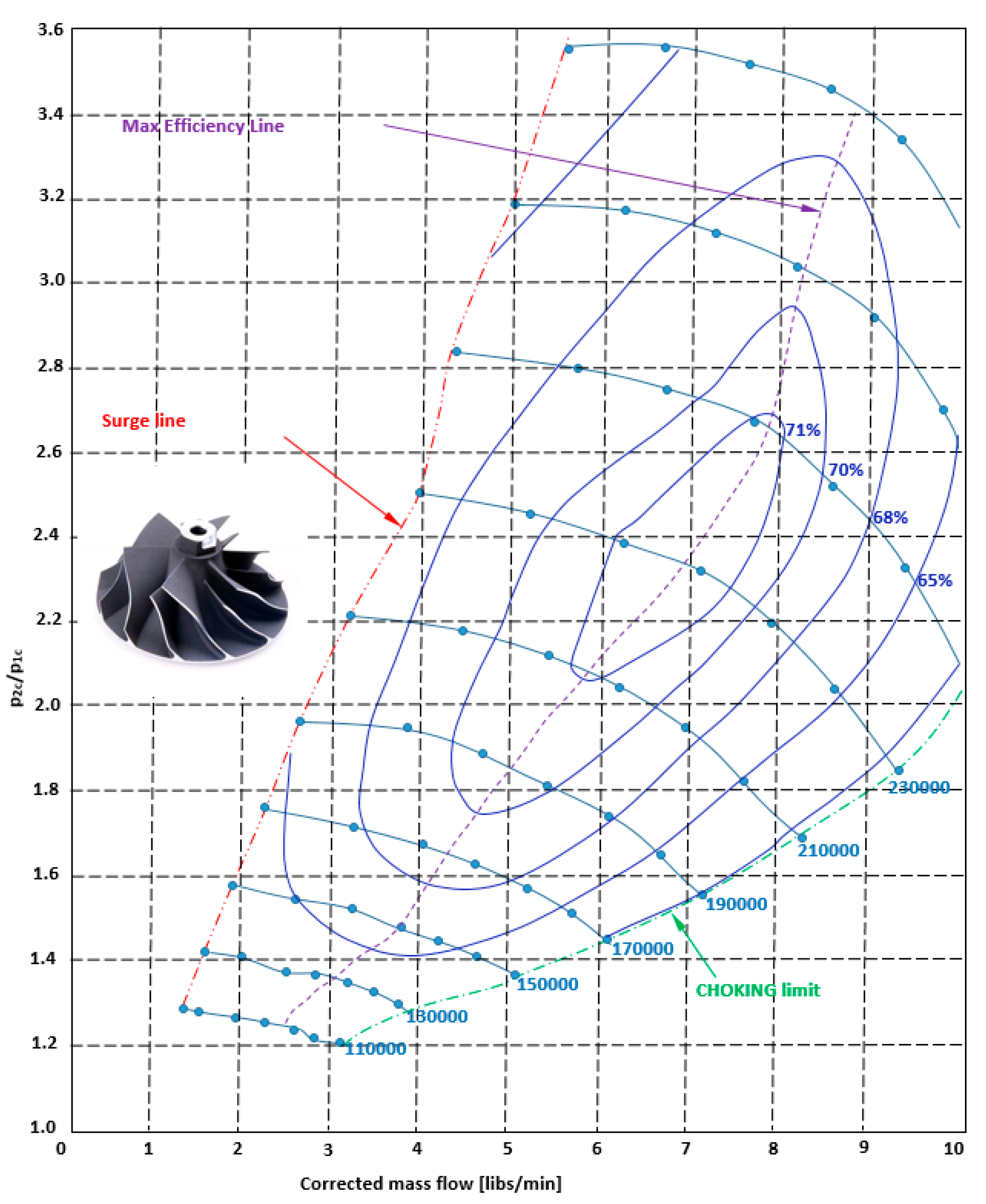
Figure 2.
Required power trend depending on the ICE engine rotational speed.

Figure 3.
Inlet forward radial turbine reference layout.

Figure 4.
(a) GT 20 impeller; (b) operative map.

Figure 5.
Power performance as a function of the speed of rotation of the ICE engine.

Figure 6.
Turbine (orange) and compressor (blue) power in function of ICE rpms.


Table 1.
Designed compressor specifications.
| 0.02 | kg/s | ||||||
| β | 1.4 | p1 | 101000 | Pa | |||
| cp | 1004 | J/kg K | |||||
| T1 | 293 | K | T2 | 337 | K | ||
| ω | 14653 | rad/s | |||||
| ε | 0.42 | ||||||
| ψ2 | 1 | Rρ | 0.5 | ||||
| LEUL | cp (T2-T1) | 44652.74 | J/kg K | ψ1 | 0 | ||
| U2 | (LEUL/φ2)1/2 | 211.3119 | m/s | ϕ1 | 0.3 | ||
| r2 | U/ω | 0.014421 | m/s | ϕ2 | 0.55 | ||
| δp | 0.98 | ||||||
| ΔΤ | 22.23742 | χ | 0.65 | (1-χ2) | 0.5775 | ||
| ρ1 | 1.20108 | ||||||
| 1 | 0.016652 | ||||||
| r1e | 0.011005 | m | |||||
| r1i | 0.007153 | m |
Table 2.
GT12 compressor operation at different ICE engine rotation regimes.
| rpm ICE | rpm | βc | Tin [K] | Tout [K] | P [W] | η | |
|---|---|---|---|---|---|---|---|
| 2000 | 0.021 | 145000 | 1.42 | 298.4 | 344 | 920.71 | 0.68 |
| 3500 | 0.0408 | 180000 | 1.64 | 297.5 | 354 | 2474.39 | 0.8 |
| 5500 | 0.0619 | 210000 | 1.84 | 297.5 | 366.8 | 4444.96 | 0.82 |
Table 3.
Turbine specifications.
| 0.0021 | kg/s | ||||||
| β | 1.4 | p2 | 101000 | Pa | |||
| cp | 1414 | J/kg K | |||||
| T1 | 980 | K | T2 | 907 | K | ||
| ω | 6280 | rad/s | |||||
| ε | 0.23 | ||||||
| φ1 | 1 | Rρ | 0.5 | ||||
| LEUL | cp (T2-T1) | 103194.4 | J/kg K | φ2 | 0 | ||
| U1 | (LEUL/φ1))1/2 | 321.2389 | m/s | Φ1 | 0.3 | ||
| r1 | U/ω | 0.051153 | m/s | Φ2 | 0.4 | ||
| δp | 0.98 | ||||||
| ΔΤ | 36.49025 | χ | 0.65 | (1-χ2) | 0,5775 | ||
| ρ2 | 0.387992 | ||||||
| 2 | 0.005412 | ||||||
| r2e | 0.011159 | m | |||||
| r2i | 0.007253 | m |
Table 4.
GT20 turbine operation at different ICE engine rotation regimes.
| rpm ICE | rpm | βe | Tin [K] | Tout [K] | P [W] | η | |
|---|---|---|---|---|---|---|---|
| 2000 | 0.024 | 82170 | 1.2 | 954 | 922 | 780 | 0.87 |
| 3500 | 0.04 | 134483 | 1.6 | 1005 | 930 | 3510 | 0.86 |
| 5500 | 0.07 | 164002 | 2.00 | 1045 | 932 | 9500 | 0.81 |
Publisher’s Note: MDPI stays neutral with regard to jurisdictional claims in published maps and institutional affiliations. |
© 2020 by the author. Licensee MDPI, Basel, Switzerland. This article is an open access article distributed under the terms and conditions of the Creative Commons Attribution (CC BY) license (https://creativecommons.org/licenses/by/4.0/).
Share and Cite
MDPI and ACS Style
Capata, R. New Power Train Concept for a City Hybrid Vehicle. Proceedings 2020, 58, 6. https://doi.org/10.3390/WEF-06926
AMA Style
Capata R. New Power Train Concept for a City Hybrid Vehicle. Proceedings. 2020; 58(1):6. https://doi.org/10.3390/WEF-06926
Chicago/Turabian StyleCapata, Roberto. 2020. "New Power Train Concept for a City Hybrid Vehicle" Proceedings 58, no. 1: 6. https://doi.org/10.3390/WEF-06926