Proceeding Paper

XRD Data Visualization, Processing and Analysis with d1Dplot and d2Dplot Software Packages †

1
ALBA Synchrotron Light Source, 08290 Barcelona, Spain
2
Institut de Ciència de Materials de Barcelona (ICMAB-CSIC), 08193 Barcelona, Spain
*
Author to whom correspondence should be addressed.
Presented at the 2nd International Electronic Conference on Crystals, 10–20 November 2020; Available online: https://iocc_2020.sciforum.net/.
Proceedings 2020, 62(1), 9; https://doi.org/10.3390/proceedings2020062009
Published: 31 December 2020
(This article belongs to the Proceedings of The 2nd International Online Conference on Crystals)

Abstract

:
The d1Dplot and d2Dplot computer programs have been developed as user-friendly tools for the inspection and processing of 1D and 2D X-ray diffraction (XRD) data, respectively. d1Dplot provides general tools for data processing and includes the ability to generate comprehensive 2D plots of multiple patterns to easily follow transformation processes. d2Dplot is a full package for 2D XRD data. Besides general processing tools, it includes specific data analysis routines for the application of the through-the-substrate methodology [Rius et al. IUCrJ 2015, 2, 452–463]. Both programs allow the creation of a user compound database for the identification of crystalline phases. The software can be downloaded from the ALBA Synchrotron Light Source website and can be used free of charge for non-commercial and academic purposes.

1. Introduction

The treatment of experimental X-ray diffraction (XRD) data normally involves several steps of processing and analysis, which often require a visual inspection of the data to follow and validate the final results. Starting from the data collection, the visual inspection may become especially important to check in detail the measured data during non-routine experiments or also when decisions on the experimental conditions should be taken on the fly (e.g., in case of synchrotron beamtime limitations). These two situations are really common nowadays due to the increasing availability of cutting-edge XRD instrumentation and techniques. On the one hand, it opens the possibility of developing new measurement techniques and methodologies and, on the other hand, it is changing the tendency of the experiments towards in situ and in operando studies which often require non-standard setups. For both scenarios the availability of XRD-specific tools providing good plotting capabilities and processing options in a user-friendly environment is really helpful. The d1Dplot and d2Dplot [1] computer programs for 1D and 2D XRD data, respectively, have been developed prioritizing these aspects.
Our research group has been devoted for a long time to the development of methodologies to obtain information from diffraction data. From the recent through-the-substrate methodology (tts-µXRD) [2] or the latest developments on the origin-free modulus sum function phasing method [3], to the well-established full pattern matching DAjust software [4], the Rietveld refinement program RIBOLS or the direct-space strategy TALP [5] to solve molecular structures from powder diffraction data. The data plotting capabilities were never a priority for us since there are plenty of available tools that can plot 1D and 2D XRD data as part of their data analysis capabilities, such as WinPLOTR [6], Fit2D [7], GSAS [8], EXPO [9], JPowder [10], Highscore [11] or TOPAS [12] among others. However, recently, two reasons pushed the development of our own software d1Dplot and d2Dplot. Firstly, the necessity of a devoted tool for the testing of the tts-µXRD methodology allowing a thorough inspection of the diffraction images with specific functions, and secondly, the need of cross-platform, user-friendly and customizable tools for their integration on a synchrotron beamline computer.

2. Features Overview

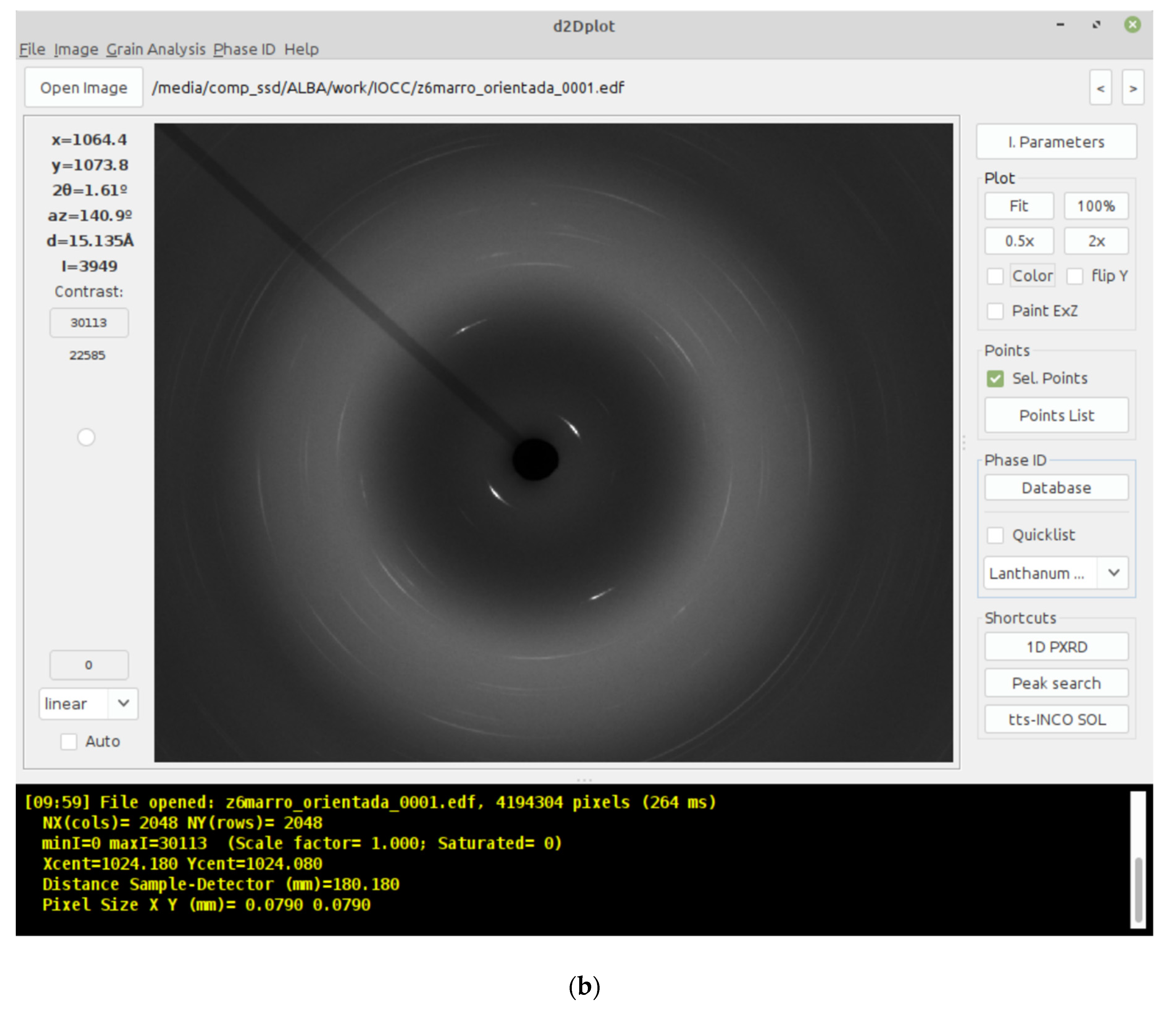
The programs d1Dplot and d2Dplot have been developed prioritizing the ease-of-use and the visualization of the diffraction data. They are composed of a main window (Figure 1) that displays the loaded XRD data and provides access to all the display-related options and to all the processing and analysis operations from a top menu. The XRD data can be navigated using the mouse (left, right, middle buttons and the wheel) and live information of the region under the cursor is displayed. In this section, the most relevant aspects of both programs will be shortly described. For a more in-depth definition of the file formats, operations and functionality, one should refer to the user manuals.

2.1. d2Dplot

d2Dplot provides the capabilities to manage 2D XRD data. It supports several common data formats and the instrumental parameters are read from the header when possible. Otherwise, they can be manually set on the program or, alternatively, they can be calibrated from a 2D XRD image of a calibrant substance (typically LaB6 or Si) using an ellipse fitting procedure. The basic processing available for 2D XRD data includes the conversion between data formats, summation and subtraction of frames, background estimation, definition of excluded zones, the conversion to 1D XRD data and the generation of azimuthal plots. All these processing operations include their own options such as the possibility to apply geometrical corrections or to define azimuthal bins in the case of the 1D powder pattern generation. All the operations with their respective options have been described in depth in a previous publication [1] and in the user manual.
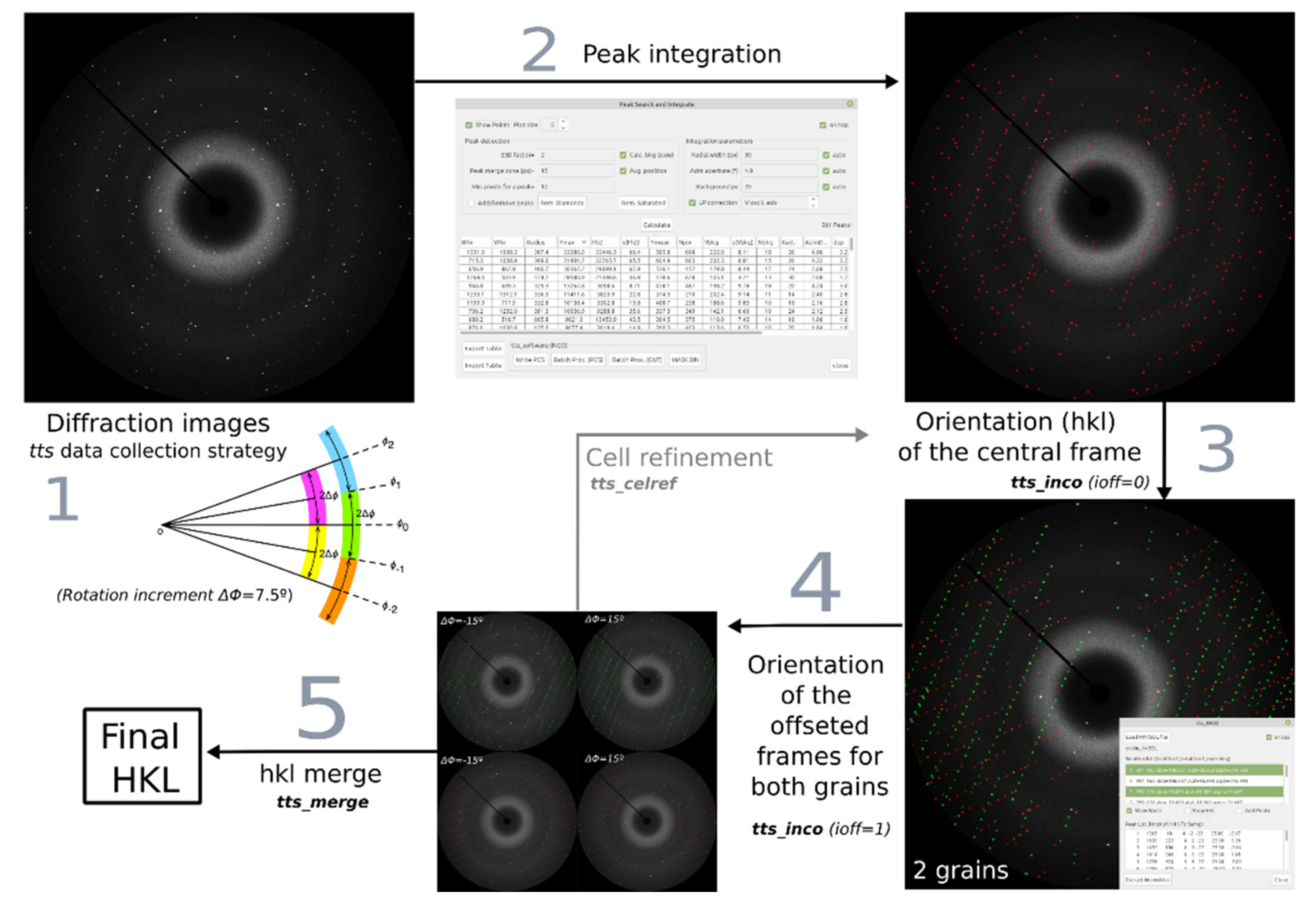
One specific feature of d2Dplot is the inclusion of a set of tools for the application of the tts-µXRD methodology (Figure 2) including a graphical frontend to its implementation in the tts_software [13]. The aim of the tts-µXRD methodology is to obtain a single-crystal-like dataset from the grains contained in thin-sections of materials mounted on glass substrates. The intensities are extracted from a few 2D XRD frames collected while rotating the sample in wide consecutive and partially overlapped scans. Then, the orientation of each of the grain(s) is determined and the intensities are scaled and merged, so that the resulting single-crystal dataset can be used for structure solution or refinement. To this purpose, d2Dplot implements a peak identification module responsible for finding the diffraction peaks on the images and extracting their intensity together with additional information to be used in the following orientation-search step. Then, the tts_software module generates the input files to launch the corresponding subroutines (tts_inco, tts_merge, tts_cellref) involved in the different steps of the workflow and also to display their intermediate outputs.

2.2. d1Dplot

d1Dplot provides the capabilities to work with 1D XRD data (i.e., powder diffraction). The most common file formats are supported, including: (1) two or three-columns ASCII text files (where usually the first column is the diffraction angle 2θ, the second is the intensity and the third is an estimated standard deviation of the intensity) which may contain header lines with instrumental information such as the wavelength; (2) list of intensities in free format with a first line specifying the initial 2θ, step size and final 2θ; (3) GSAS Standard Powder Data File [8]; (4) FullProf PRF file with the observed, calculated and difference profiles [14]; (5) Panalytical XRDML format [15]; and (6) the G(r) output file from pdfgetx3 [16].
One strong aspect of d1Dplot is the panel at the rightmost part of the main window where all the visualization parameters can be tuned. There, it is possible to define the behavior of the axes when navigating the data (with fixed or dynamic values), set the axes separations, the displayed zone limits, partial zoom range, plot and axes titles, legend, data labels and almost everything that affects the visual appearance. The XRD data window can be exported as a PNG image or a SVG vector graphics file.
Multiple Powder Pattern Processing. The most important feature of d1Dplot is the capability to manage several diffraction patterns in a comfortable way. All the loaded data are shown on a table in the bottom part of the main window that contains the following columns:
  • nP: Pattern number.
  • nS: Series number. One pattern may contain multiple series (data, background, peaks, etc…)
  • Name: Name of the series (by default the filename).
  • Color: Color of the series.
  • Scale: Y scale of the series.
  • ZerOff: Offset of the series in the X axis.
  • Wavel: Wavelength of the pattern.
  • Xunits: Units of the X-axis. By default 2θ.
  • YOffset: Offset of the series in the Y axis.
  • Marker: Marker size.
  • Line: Line width.
  • ErrBars: To show the error bars on Y.
  • Show: To show or hide the current series on the plot area.
  • Type: To differentiate and apply different plotting styles depending on the content of the data series (powder XRD data, peaks, background estimation or discreet 2θ values to be used as reference of crystallographic phases).
All the values can be set directly on the table by clicking with the mouse, for one or for several patterns at once. Also, right mouse button clicking on the table will show a context menu with possible operations on the selected patterns, such as editing their parameters or summing them. Additional operations on the selected patterns can be accessed through the Processing tab of the top menu. Among the available operations there is the background estimation, which can use a smoothing procedure [17] or the interpolation of polynomial or spline functions, and the peak finding routine that allows exporting a list of peaks for further analysis (e.g., indexing with DICVOL) [18].
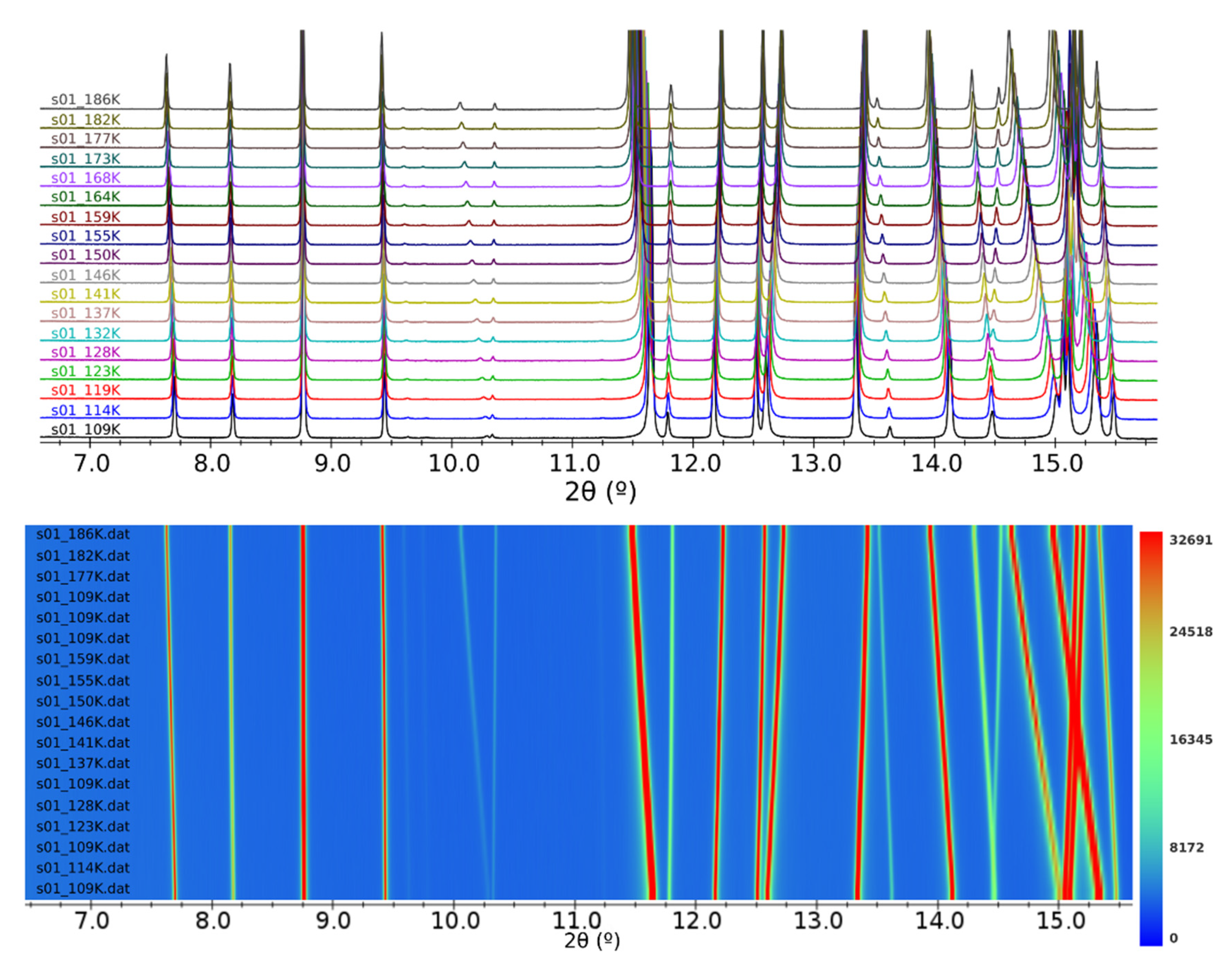
To conveniently compare multiple diffraction patterns two options are available from the Plot Options tab on the top menu: (1) the sequential Y-offset, that results in a stacking of the selected patterns along the Y axis by giving the desired offset between patterns; and (2) the 2D plot, that generates a heatmap image with the intensity as color and some options to control the aspect of the plot (Figure 3). For data collected at different wavelength, X-units can be changed to Q or d-spacing.
Finally, a project file can be saved containing all the patterns and the visual customization in order to continue the data processing or the preparation of figures between different sessions.

2.3. Compound Database

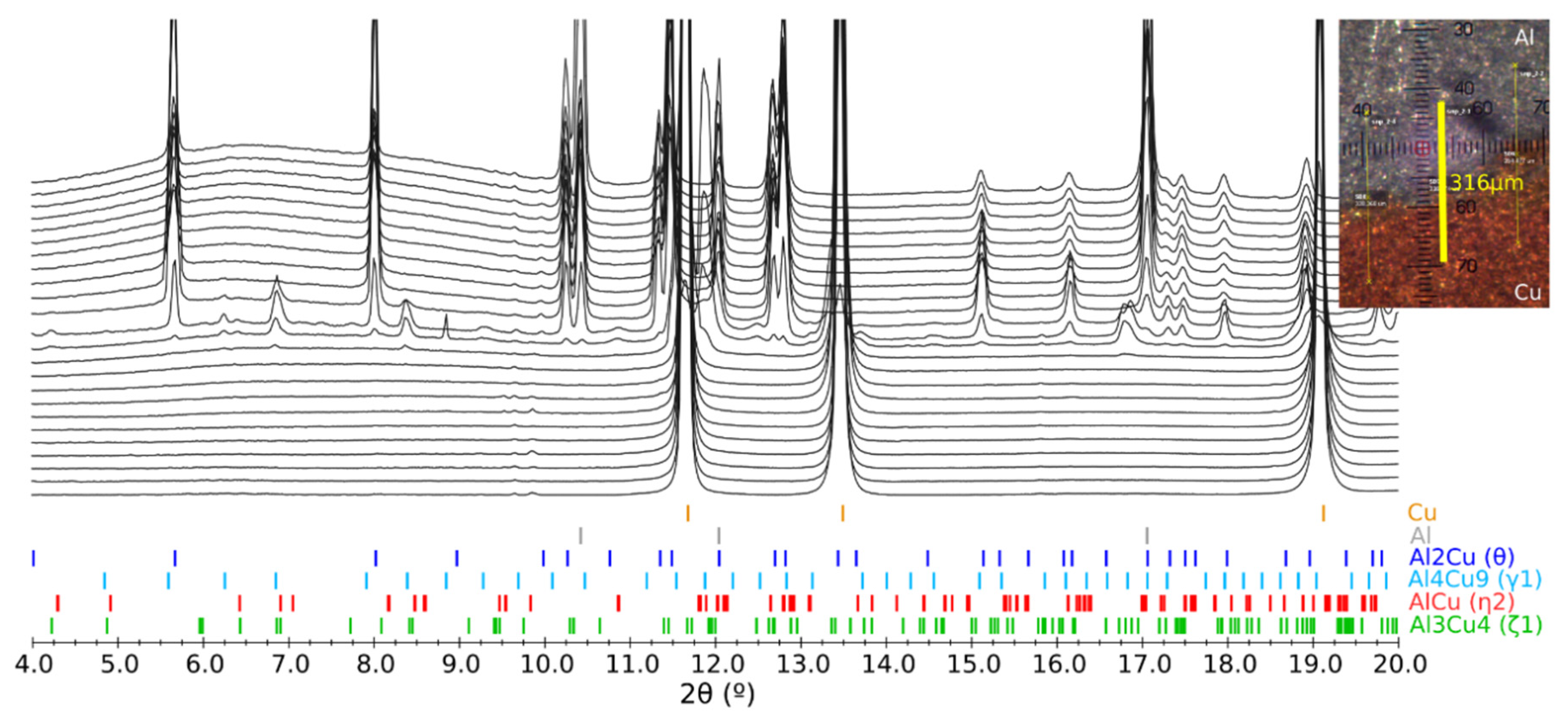
Both programs include a database module that can read an ASCII file containing crystallographic information of compounds. It basically consists of a list of d-spacing positions for each compound that can be entered manually, calculated from a given unit cell and a space group, or generated from a CIF file [20] including, optionally, the intensities. The programs use this list to display the expected diffraction peaks (the Debye rings in the case of 2D XRD) taking into account the instrumental parameters. In d1Dplot, multiple entries of the database can be added as data series, for example, to be displayed as possible phases when dealing with phase identification problems on mixtures (Figure 4). The aim of this tool it to help on the data interpretation by introducing a few known phases for specific problems and not a complete phase identification procedure, as there are already very good tools for this purpose, such as the Sieve software of ICDD coupled to its PDF4 database [21] or the QualX2 software [22].

2.4. Comand-Line Mode

The most used operations implemented in both programs can be also executed from the command-line interface without opening the graphical interface. This is intended to perform batch operations on multiple XRD data and to be able to attach these processing operations to data collection procedures to be performed automatically after data acquisitions. Also, the programs can be launched from the command line opening directly specific datasets by providing them as arguments.

3. Applications

Both programs are relatively recent but there are already some cases where they have been proved useful. Also, in the Materials Science and Powder Diffraction beamline of the ALBA Synchrotron [24] the programs are integrated on the beamline computers and used routinely to perform processing operations on the fly and to visualize the collected data. One example that takes full advantage of the software capabilities is the mapping of cultural heritage samples for phase identification using a small beam and a 2D detector. In this case, the 2D XRD frames are inspected, automatically converted to 1D powder patterns (sometimes for thousands of collected images) and plotted with d1Dplot to check the distribution of phases in the different zones of interest [25,26]. In addition to analysis of phases, the same workflow has been used to evaluate the texture and microstructure of the hydroxyapatite crystals on crocodile teeth [27] and of calcium oxalate in kidney stones [28], the latter extensively using the azimuthal plotting capabilities of d2Dplot to differentiate between oxalate species. Obviously, d2Dplot is also being used in the cases where the tts-µXRD methodology is applied [29,30]. On the other hand, d1Dplot is being continuously used in studies that involve crystallographic changes of the sample in situ, for example, to follow crystallographic changes during chemical reactions, temperature ramps or gas absorption of porous materials [31].
To complement data visualization and processing, d1Dplot can be used to prepare comprehensive figures for publication either in scientific journals or in experimental reports. The possibility to tune most of the visual aspects allows creating tailor-made figures in a reproducible way between different datasets or sessions. Also, it is worth noting that the user-friendliness of the programs is really appreciated by non-experienced users, as they can rapidly get used to them and, consequently, become independent from data processing.
Finally, it should be mentioned that this software is also a good tool to teach various aspects of crystallography. In the personal experience of the authors, two specific ones which proved quite useful are: (1) the ability of d1Dplot to plot the reflection positions and to see how these positions move when changing the crystallographic and/or the instrumental parameters; (2) similarly, with d2Dplot, the possibility of plotting the Debye rings of a reference substance for specific instrumental conditions and geometrical configurations.

4. Technical Description and Availability

d1Dplot and d2Dplot have been programmed using the Java language and the only requirement to run is to have the Java Runtime Environment (JRE) installed. The following third-party libraries have been used: Apache Commons Math and Apache Batik (versions 3.6.1 and 1.8 respectively, Apache license), MigLayout (version 4.3, written by Mikael Grev, BSD license) and imageJ (version 1.50i [32], Public Domain). The programs can be downloaded from the ALBA Synchrotron Light Source web site [33] and can be used free of charge for non-commercial and academic purposes. A user manual is included and a configuration file is written in the program folder on first launch. Both programs are in continuous development and any feedback to the authors (reporting of errors, suggestions, etc.) is kindly appreciated.

Author Contributions

d1Dplot software, O.V.; d2Dplot software, J.R. and O.V.; resources, O.V. and J.R.; writing—original draft preparation, O.V.; writing—review and editing, O.V. and J.R. All authors have read and agreed to the published version of the manuscript.

Funding

This research was funded by MINECO, grant number MAT2015-67593-P, and Severo Ochoa program for Centers of Excellence in R&D, grant number SEV-2015-0496.

Acknowledgments

O.V. thanks the BL04-MSPD beamline staff of the ALBA Synchrotron (François Fauth, Catalin Popescu and Aleksandr Missiul) for the feedback about the usage of the programs and to the ALBA Synchrotron for their continued financial support. Thanks are also due to Fernando Colombo (CICTERRA-CONICET, Córdoba, Argentina) for providing the Dickinsonite sample used in the tts-µXRD example; to Imanol de Pedro (CITIMAC, Facultad de Ciencias, Universidad de Cantabria) for the 1-ethyl-2,3-dimethylimidazolium bromide sample and to Pascal Schmalen (University of Luxembourg) for the laser welded Al-Cu sample shown in the figures as example datasets.

Conflicts of Interest

The authors declare no conflict of interest.

References

  1. Vallcorba, O.; Rius, J. d2Dplot: 2D X-ray diffraction data processing and analysis for through-the-substrate microdiffraction. J. Appl. Crystallogr. 2019, 52, 478–484. [Google Scholar] [CrossRef]
  2. Rius, J.; Vallcorba, O.; Frontera, C.; Peral, I.; Crespi, A.; Miravitlles, C. Application of synchrotron through-the-substrate microdiffraction to crystals in polished thin sections. IUCrJ 2015, 2, 452–463. [Google Scholar] [CrossRef]
  3. Rius, J. Novel phasing method using the origin-free modulus sum function expressed in terms of the absolute electron density. Acta Crystallogr. Sect. A Found. Adv. 2020, 76, 489–493. [Google Scholar] [CrossRef]
  4. Vallcorba, O.; Rius, J.; Frontera, C.; Peral, I.; Miravitlles, C. DAJUST: A suite of computer programs for pattern matching, space-group determination and intensity extraction from powder diffraction data. J. Appl. Crystallogr. 2012, 45, 844–848. [Google Scholar] [CrossRef]
  5. Vallcorba, O.; Rius, J.; Frontera, C.; Miravitlles, C. TALP: A multisolution direct-space strategy for solving molecular crystals from powder diffraction data based on restrained least squares. J. Appl. Crystallogr. 2012, 45, 1270–1277. [Google Scholar] [CrossRef]
  6. Roisnel, T.; Rodríquez-Carvajal, J. WinPLOTR: A Windows Tool for Powder Diffraction Pattern Analysis. Mater. Sci. Forum 2001, 378–381, 118–123. [Google Scholar] [CrossRef]
  7. Hammersley, A.P. FIT2D: A multi-purpose data reduction, analysis and visualization program. J. Appl. Crystallogr. 2016, 49, 646–652. [Google Scholar] [CrossRef]
  8. Larson, A.C.; Von Dreele, R.B. General Structure Analysis System (GSAS). Los Alamos Natl. Lab. Rep. LAUR 2004, 86–748. [Google Scholar]
  9. Altomare, A.; Cuocci, C.; Giacovazzo, C.; Moliterni, A.; Rizzi, R.; Corriero, N.; Falcicchio, A. EXPO2013: A kit of tools for phasing crystal structures from powder data. J. Appl. Crystallogr. 2013, 46, 1231–1235. [Google Scholar] [CrossRef]
  10. Markvardsen, A.J.; Puphaiboon, K.; Arjeneh, M.; Shankland, K.; Guest, H.L.; Griffin, T.A.N.; Badham, D.R.; Flannery, D.W. Jpowder: A Java-based program for the display and examination of powder diffraction data. J. Appl. Crystallogr. 2010, 43, 1532–1534. [Google Scholar] [CrossRef]
  11. Highscore Software. Available online: https://www.malvernpanalytical.com/en/products/category/software/x-ray-diffraction-software/highscore (accessed on 19 October 2020).
  12. Coelho, A.A. TOPAS and TOPAS-Academic: An optimization program integrating computer algebra and crystallographic objects written in C++. J. Appl. Crystallogr. 2018, 51, 210–218. [Google Scholar] [CrossRef]
  13. TTS_Software, ICMAB-CSIC. Available online: https://departments.icmab.es/crystallography/software (accessed on 19 October 2020).
  14. Rodríguez-Carvajal, J. Recent advances in magnetic structure determination by neutron powder diffraction. Phys. B 1993, 192, 55–69. [Google Scholar] [CrossRef]
  15. Degen, T. XrdML, a new way to store (and exchange) X-ray powder diffraction measurement data. arXiv 2002, arXiv:physics/0210067. [Google Scholar]
  16. Juhás, P.; Davis, T.; Farrow, C.L.; Billinge, S.J.L. PDFgetX3: A rapid and highly automatable program for processing powder diffraction data into total scattering pair distribution functions. J. Appl. Crystallogr. 2013, 46, 560–566. [Google Scholar] [CrossRef]
  17. Brückner, S. Estimation of the background in powder diffraction patterns through a robust smoothing procedure. J. Appl. Crystallogr. 2000, 33, 977–979. [Google Scholar] [CrossRef]
  18. Boultif, A.; Louër, D. Powder pattern indexing with the dichotomy method. J. Appl. Crystallogr. 2004, 37, 724–731. [Google Scholar] [CrossRef]
  19. de Pedro, I.D.; García-Saiz, A.; Dupont, J.; Migowski, P.; Vallcorba, O.; Junquera, J.; Rius, J.; Rodríguez Fernández, J. On the colossal and highly anisotropic thermal expansion exhibited by imidazolium salts. Cryst. Growth Des. 2015, 15, 5207–5212. [Google Scholar] [CrossRef]
  20. Hall, S.R.; Allen, F.H.; Brown, I.D. The crystallographic information file (CIF): A new standard archive file for crystallography. Acta Crystallogr. Sect. A Found. Adv. 1991, 47, 655–685. [Google Scholar] [CrossRef]
  21. Faber, J.; Fawcett, T. The Powder Diffraction File: Present and future. Acta Crystallogr. Sect. B Struct. Sci. Cryst. Eng. Mater. 2002, 58, 325–332. [Google Scholar] [CrossRef]
  22. Altomare, A.; Corriero, N.; Cuocci, C.; Falcicchio, A.; Moliterni, A.; Rizzi, R. QUALX2.0: A qualitative phase analysis software using the freely available database POW_COD. J. Appl. Crystallogr. 2015, 48, 598–603. [Google Scholar] [CrossRef]
  23. Schmalen, P.; Plapper, P.; Peral, I.; Titov, I.; Vallcorba, O.; Rius, J. Composition and phases in laser welded Al-Cu joints by synchrotron X-ray microdiffraction. Procedia CIRP 2018, 74, 27–32. [Google Scholar] [CrossRef]
  24. Fauth, F.; Peral, I.; Popescu, C.; Knapp, M. The new Material Science Powder Diffraction beamline at ALBA Synchrotron. Powder Diffr. 2013, 28, S360–S370. [Google Scholar] [CrossRef]
  25. Emami, M.; Rozatian, A.S.H.; Vallcorba, O.; Anghelone, M.; Hadian Dehkordi, M.; Pritzel, C.; Trettin, R. Synchrotron micro-XRD study, the way toward a deeper characterizing the early prehistoric Iranian glass cylinders from Late Bronze Age (1280 BC). Eur. Phys. J. Plus 2020, 135, 1–14. [Google Scholar] [CrossRef]
  26. Beltrán, M.; Schibille, N.; Brock, F.; Gratuze, B.; Vallcorba, O.; Pradell, T. Modernist enamels: Composition, microstructure and stability. J. Eur. Ceram. Soc. 2020, 40, 1753–1766. [Google Scholar] [CrossRef]
  27. Vallcorba, O.; Canillas, M.; Audije-Gil, J.; Barroso-Barcenilla, F.; González-Martín, A.; Molera, J.; Rodríguez, M.A.; Cambra-Moo, O. Synchrotron X-ray microdiffraction to study life history events in Cretaceous crocodylomorphs through dental structures. Cretac. Res. 2020. under review. [Google Scholar]
  28. Valido, I.H.; Fuentes-Cebrian, V.; Boada, R.; Vallcorba, O.; Resina-Gallego, M.; Valiente, M.; López-Mesas, M. Discriminating the formation origin of calcium oxalate monohydrate in kidney stones via synchrotron microdiffraction. Cryst. Growth Des. 2020. under review. [Google Scholar] [CrossRef]
  29. Vallcorba, O.; Casas, L.; Colombo, F.; Frontera, C.; Rius, J. First terrestrial occurrence of the complex phosphate chladniite: Crystal-structure refinement by synchrotron through-the-substrate microdiffraction. Eur. J. Mineral. 2017, 29, 287–293. [Google Scholar] [CrossRef]
  30. Crespi, A.; Vallcorba, O.; Šics, I.; Rius, J. First identification and compositional study of brown aerinite directly on polished thin-sections by synchrotron through-the-substrate microdiffraction. Eur. J. Mineral. 2019, 31, 999–1005. [Google Scholar] [CrossRef]
  31. Portolés-Gil, N.; López-Periago, A.M.; Borrás, A.; Fraile, J.; Solano, E.; Vallcorba, O.; Planas, J.G.; Ayllón, J.A.; Domingo, C. Tuning the Structure and Flexibility of Coordination Polymers via Solvent Control of Tritopic Triazine Conformation during Crystallization. Cryst. Growth Des. 2020, 20, 3304–3315. [Google Scholar] [CrossRef]
  32. Schneider, C.A.; Rasband, W.S.; Eliceiri, K.W. NIH Image to ImageJ: 25 years of image analysis. Nat. Methods 2012, 9, 671–675. [Google Scholar] [CrossRef]
  33. ALBA Synchrotron (MSPD Beamline, Preparing Your Experiment and Software Section). Available online: https://www.cells.es/en/beamlines/bl04-mspd/preparing-your-experiment (accessed on 19 October 2020).
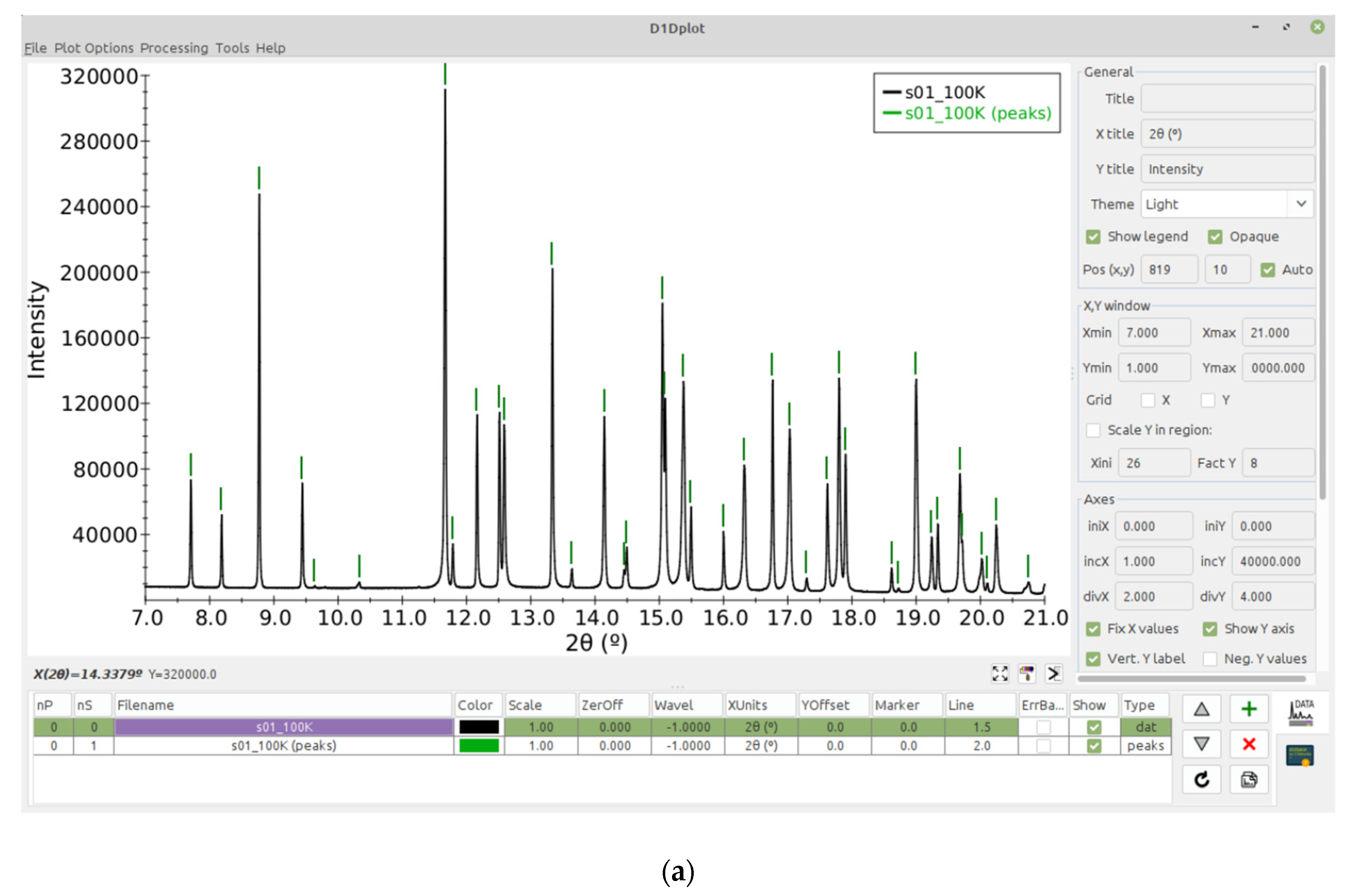
Figure 1. (a) Main windows of the programs: (a) d1Dplot showing the right panel with visualization options and the table with the list of opened data series, in this case a powder diffraction pattern and a peaks series; (b) d2Dplot showing an opened 2D XRD image with the on-screen cursor information on the left panel and the most used options on the right panel.
Proceedings 62 00009 g001aProceedings 62 00009 g001b
Figure 2. Workflow of the application of the tts-µXRD methodology. In the first step data are collected using the rotation method with wide and partially-overlapped angular increments. The second step is the integration of all the reflections on the images. Then, in the third step the orientation of the grain(s) contained in the central frame is determined. In this example (Dickinsonite phosphate mineral) there are two grains filling the measured microvolume. In the next step the orientation of the offset frames for the different grains is determined and, if necessary, the unit cell is refined. Finally, the last step is the scaling and merging of all the partial hkl from the different grains and offsets.
Proceedings 62 00009 g002
Figure 3. The two plot options for multiple patterns: sequential Y-offset (top) and 2D heatmap (bottom). XRD data of 1-ethyl-2,3-dimethylimidazolium bromide at different temperatures with peak displacement due to the thermal expansion [19].
Proceedings 62 00009 g003
Figure 4. Plotting of the diffraction patterns along a laser welded Al-Cu joint (along the yellow line in the inset) with the assignment of the intermetallic phases formed during the process [23].
Proceedings 62 00009 g004
Publisher’s Note: MDPI stays neutral with regard to jurisdictional claims in published maps and institutional affiliations.