Proceeding Paper

Wideband Reconfigurable Antenna with Beams Switching for Wireless Systems Applications †

by
Faouzi Rahmani
1,*,
Naima Amar Touhami
1,
Abdelmounaim Belbachir Kchairi
2 and
Nihade Taher
3
1
Faculty of Sciences, Abdelmalek Essaadi University, Tetuan 93030, Morocco
2
Faculty of Sciences and Techniques, Hassan II University of Casablanca, Casablanca 20006, Morocco
3
National School of Applied Sciences, Abdelmalek Essaadi University, Tetuan 93030, Morocco
*
Author to whom correspondence should be addressed.
Presented at the 14th International Conference on Interdisciplinarity in Engineering—INTER-ENG 2020, Târgu Mureș, Romania, 8–9 October 2020.
Proceedings 2020, 63(1), 36; https://doi.org/10.3390/proceedings2020063036
Published: 18 December 2020

Abstract

:
In this paper, a new wideband reconfigurable antenna with beams switching for wireless systems applications is presented and studied. The radiation pattern of the proposed antenna can be changed using the PIN diodes. The designed antenna has a bandwidth of 26.75% from 5.31 to 6.95 GHz and can steer the beam in the azimuth plane. The simulated realized gain of the antenna obtained is 5.9 dB at 5.8 GHz. The proposed antenna can operate for various wireless systems, such as Wi-Fi, WiMAX, Intelligent Transportation System (ITS) and C-band satellite. The simulated results are also presented and investigated.

1. Introduction

With the rapid development of electronic and wireless communication, performance is important in any antenna system. The reconfigurable antennas have gained more attention due to their flexibility in operating frequency, polarization and radiation pattern reconfiguration [1,2,3,4]. This makes them highly suitable for different wireless communication systems. This antenna type can electronically change its parameters in response to different environments, which has been studied extensively. This means it can satisfy the diverse requirements and strict standards of advanced wireless communication systems due to its numerous merits such as reducing size, expanding capacity and wide cover. Optical, mechanical or electronic switching can be used to accomplish reconfiguration. Electronic switching is achieved using lumped components, for example, varactor diodes [5], PIN diodes [6,7,8,9,10,11,12,13,14], RF MEMS switches [15] or FET transistors.
The reality that distinct wireless applications, such as Wi-Fi, WiMAX and ITS, use various operating bands and the exigency of Wideband reconfigurable antennas for wireless terminals is also rising. Multifunction in antennas is an important characteristic that has currently generated more interest in antenna design development. Contrast with accustomed antennas, multifunctional antennas offers the capability to dynamically alter several antenna parameters.
In recent years, this antenna type has been proposed and developed more and more. To realize the pattern reconfigurability, there are various main technical and methods in the literature. The antenna in [15] performed six operating states by monitoring the states of MEMS switches. The antenna in [16] achieved two states by controlling the state of two PIN diodes between the feed line and patch elements. Based on a circular monopole patch and three ship-shaped parasitic patches, the radiation pattern of the antenna in [17] would be reconfigured in two modes in the azimuth plane by steering the state of two PIN diodes. In Ref. [18], by shifting the states of the four PIN diodes, four pattern reconfigurable states were obtainable. To increase the antenna performance, we propose to use four radiation cells connected to a central circular patch by using PIN diodes. The PIN diodes are very reliable since there are no moving parts and are extremely low cost. Patch antenna can be integrated easily with PIN diode switches to form reconfigurable patch antennas [18,19]. In addition to the pattern reconfigurability, the objective is to increase the bandwidth and miniaturize the antenna size.
In this work, we propose a new reconfigurable radiation pattern antenna using four fan-shaped radiation cells that operate either as reflector(s) or director(s) according to the PIN diodes states, and a square planar ground. The radiation pattern can be changed into four states using four switches. The antenna main beam can be switched to four directions in the azimuth plane by controlling the states (ON or OFF) of four Microsemi MPP4203 PIN diodes [20]. The designed antenna has a bandwidth of 5.31–6.95 GHz and can operate for various wireless systems, such as Wi-Fi, WiMAX and ITS.
This work will begin by describing the wideband reconfigurable antenna design and operation principle to realize the reconfigurability of the radiation patterns. The design evolutions process for the proposed antenna and parametric study will be presented in Section 3 and Section 4, respectively. The simulation results of the proposed antenna at operating states will be presented in Section 5. Finally, the conclusion is given in Section 6.

2. Antenna Design

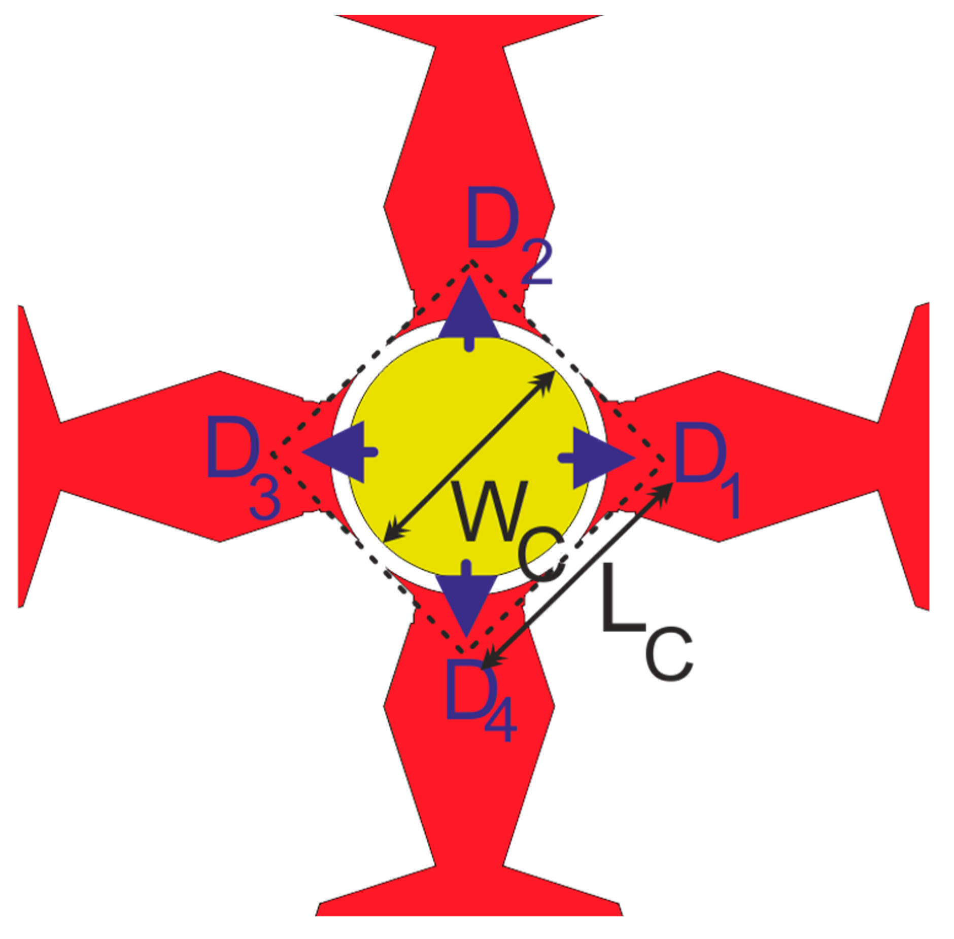
The proposed antenna consisted of a central circular patch and four radiation cells graved on h = 0.8 mm thick Rogers RT5880 substrate with a relative dielectric constant of 2.2 and a dissipation factor of 0.0009. A square-shaped ground plane is printed on the bottom surface of the substrate as shown in Figure 1. The first (yellow area) part is a circular patch located at the center of the proposed antenna, which is connected to the inner pin of the coaxial cable. The second (red area) parts are four fan-shaped radiation cells, which distribute around the antenna center symmetrically as shown in Figure 1a.
The size of the substrate is (W × L × h) = (60 mm × 60 mm × 0.8 mm). The radiation elements are connected to the central circular patch using four switches in the gap between them, the width of this gap is 0.3 mm. The four PIN diodes are mounted in the gap between the circular patch and the four parasitic patches as shown in Figure 2. This antenna was obtained after many optimizations using an electromagnetic simulator (CST Microwave Studio). The optimized parameter values of the proposed wideband reconfigurable radiation pattern antenna are given in Table 1.

3. Design Evolution Procedure

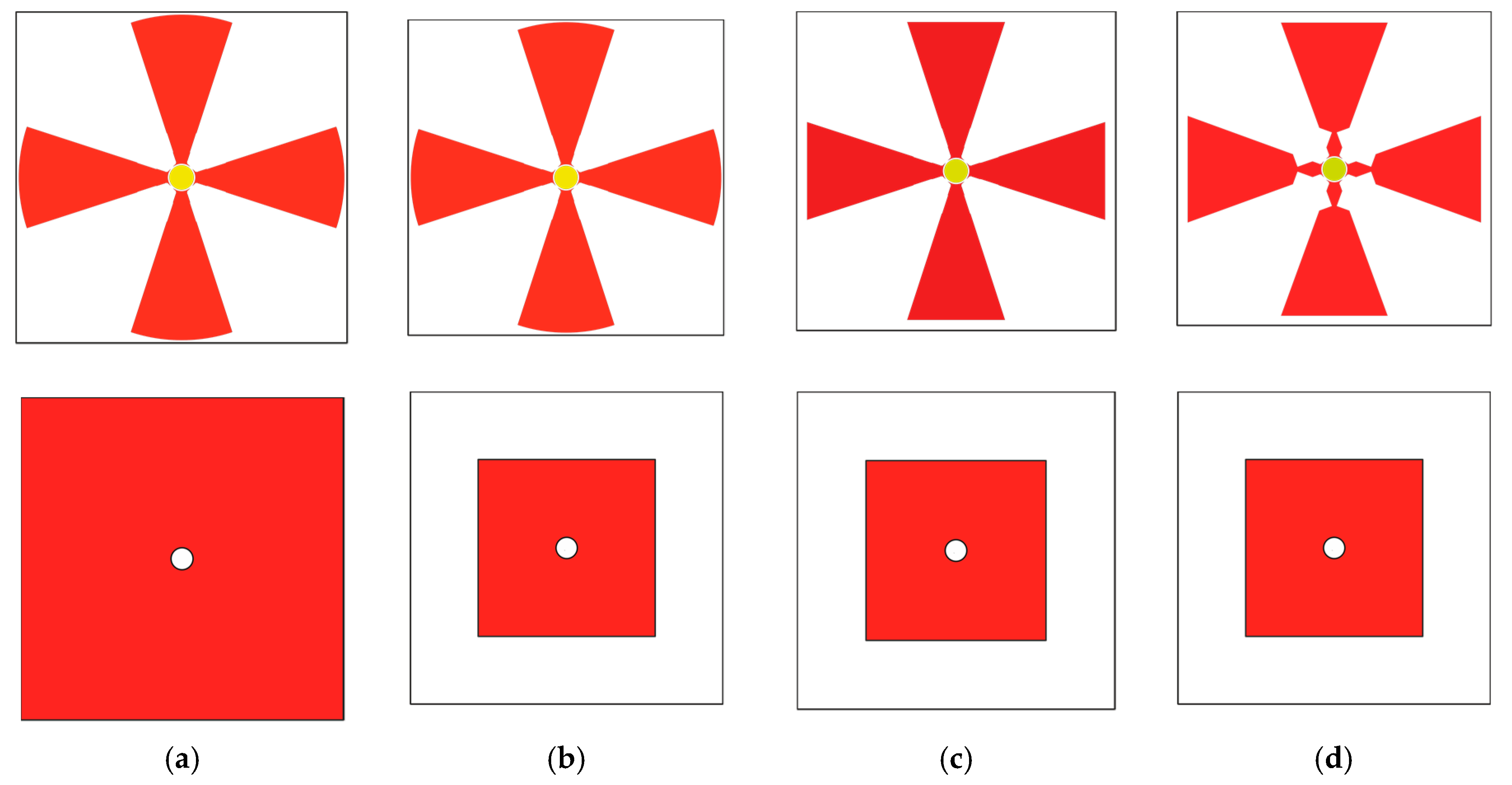
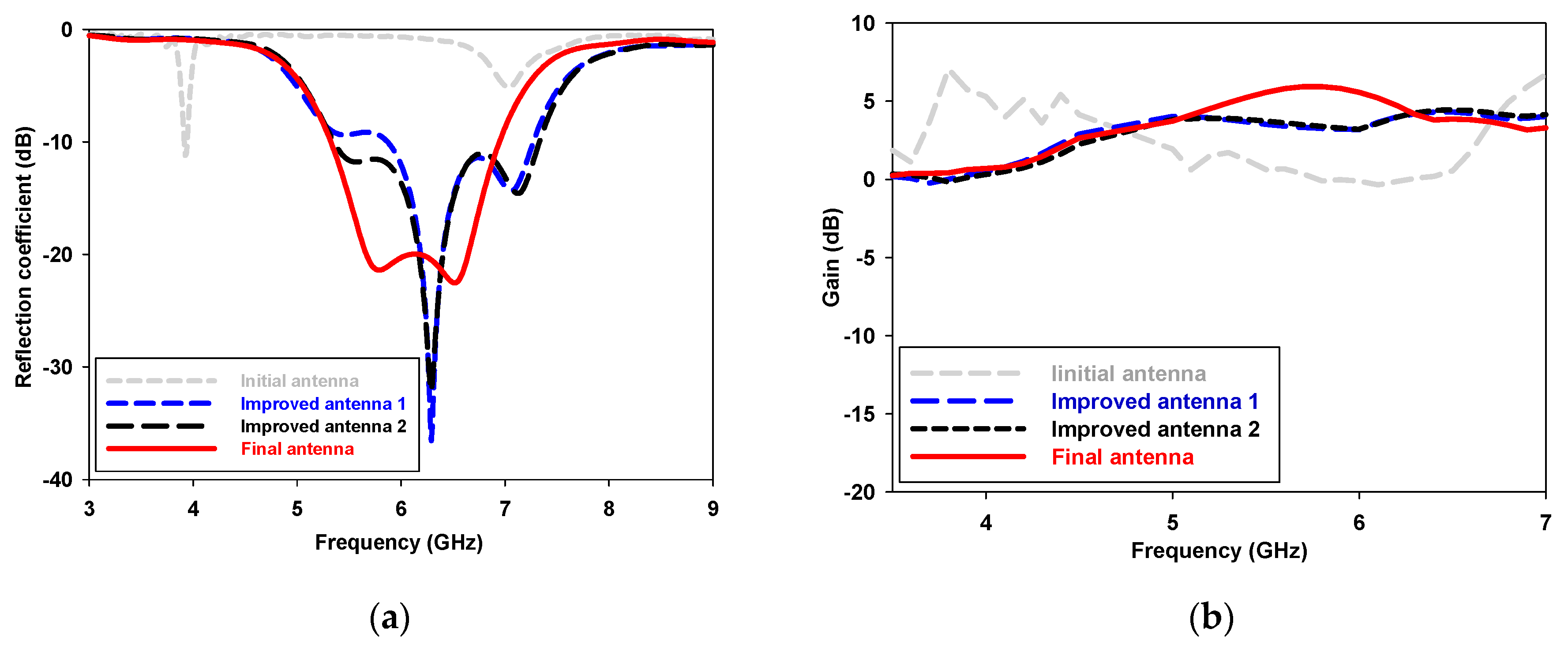
Figure 3 shows the design evolution of the proposed antenna, with corresponding results of simulated reflection coefficient S11 (dB) as shown in Figure 4a, and simulated gain realized over frequency of each step as shown in Figure 4b. The simulation results are obtained when the antenna operates in state 1. This study gives the same results for the other operation states.
The first step in the design of the proposed reconfigurable antenna is presented in Figure 3a. As can be seen from this figure, on the top side of the substrate four symmetrical circular-shaped microstrip parasitic patches are placed one opposite the other, and a circular-shaped patch is located at the center of the antenna, which is connected to the inner pin of the coaxial. On the bottom surface of the substrate, a square-shaped ground plane is printed. A resonant frequency at 3.93 GHz is created with −10 dB impedance bandwidth that ranges from 3.91 to 3.95 GHz as shown in Figure 4a. However, the maximum simulated gain value is 6.90 dB for the initial antenna at 3.93 GHz frequency as shown in Figure 3b.
In order to enhance the impedance bandwidth, a change in the ground plane was implemented as shown in Figure 3b. Meanwhile, as in the case of the previous step, on the top side of the substrate, the antenna geometry remains unchanged. As given in Figure 4a, the improved antenna 1 resonates at 6.29 GHz with −10 dB impedance bandwidth that ranges from 5.83 to 7.27 GHz. Note that the improved antenna 1 has a bandwidth greater than that of the initial antenna. On the other hand, the maximum simulated gain value is around 4.30 dB as shown in Figure 4b.
In order to improve the impedance bandwidth, a change in the parasitic patch geometry is implemented. The circular side of the radiating cells becomes rectilinear as shown in Figure 3c. As illuminated in Figure 4a, the improved antenna 2 resonates at 6.29 GHz with −10 dB impedance bandwidth that ranges from 5.35 to 7.33 GHz. Note that the improved antenna 1 has a bandwidth greater than that of the improved antenna 1. Meanwhile, the maximum simulated gain value is around 4.21 dB as shown in Figure 4b.
To make the antenna more adapted, deformation at the entry of the parasitic patches was carried out with slots in the form of triangles as shown in Figure 3d. The proposed reconfigurable antenna becomes more adapted. The designed antenna has a bandwidth of 5.31–6.95 GHz as shown in Figure 4a. Note that the final antenna has a gain greater than that of the other antennas. Meanwhile, the maximum simulated gain value at 5.8 GHz is around 6.0 dB as shown in Figure 4b. The choice of the fan-shaped design is intended to cover the whole azimuthal plane and to have a new antenna capable of yielding directive gain patterns in the azimuth plane.

4. Parametric Study

A parametric study was achieved to comprehend the influence on the proposed antenna performance. Taking state 1 as an example, the parameters are optimized for antenna performance and tabulated in Table 1. In this section, we study the effects of the main geometric parameters on reflection coefficient (S11) and antenna gain. We present a parametric study of the proposed antenna that is used to obtain the optimal values and the best performance by tuning one parameter at a time while other parameters are left invariable.

4.1. The Effect of the Length L0

The antenna reflection coefficient (S11) (dB) and the gain are simulated for different values of the length (L0) of fan-shaped radiating cells and the other dimensions remaining constant are presented in Figure 5. It can be seen that the impedance bandwidth of the proposed antenna remains stable and that the frequency resonances are shifted. As illustrated in Figure 5a, when L0 = 21 mm, the antenna becomes more adapted. On the other hand, the antenna gain remains almost stable for the 5.31–6.95 GHz band when the length L0 = 21 mm as shown in Figure 5b. Therefore, the optimal value of length is L0 = 21 mm.

4.2. The Effect of the Angle β

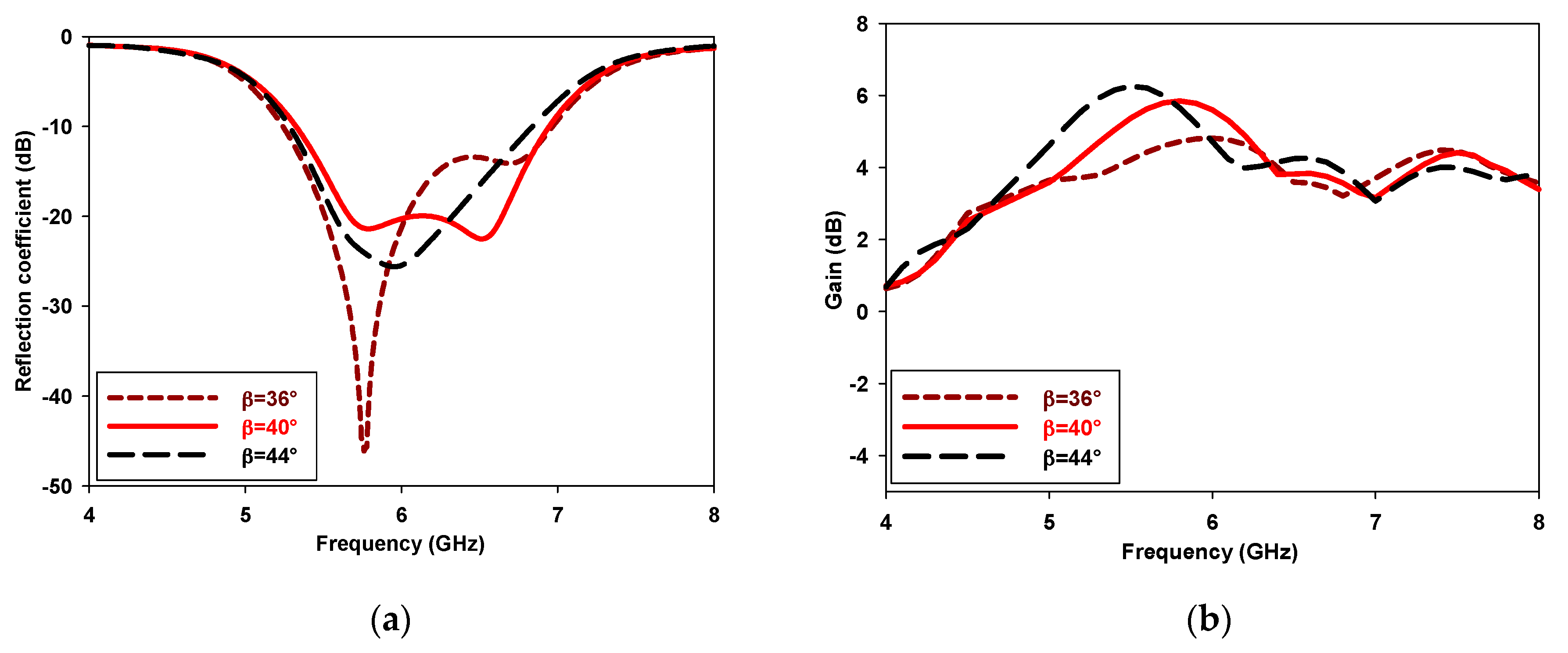
The antenna gain and parameter (S11) (dB) are also simulated as a function of the angle β variation. As presented in Figure 6a, the frequency resonances are shifted. Meanwhile, the antenna becomes more adapted when β = 40°. Likewise, the antenna gain is larger at the 5.8 GHz frequency when the angle α increases from 36° to 44° as shown in Figure 6b. Therefore, the optimum value of this angle is β = 40°.

5. Simulation Results and Discussion

Based on the PIN diode states, the different radiating elements of the antenna can be selectively powered by the circular patch. Therefore, a series of simulations was performed as given in Table 2. The PIN diode resistance and capacitance in the ON and OFF conditions are 3 Ω, 0 pF, and 25 kΩ, 0.8 pF, respectively [18,19]. By controlling the biasing of the PIN diodes, the distribution of the antenna surface current will be modified; this will deflect the direction of the antenna radiation. The radiating cells operate either as reflector(s) or director(s) according to the switches states. This shows that the proposed antenna has four operating states named as state 1 (S1), state 2 (S2), state (S3) and state 4 (S4).
The reflection coefficient (S11) (dB) of the proposed wideband reconfigurable antenna is presented in Figure 7. The simulated results show that the proposed antenna has a bandwidth of 26.75% from 5.31 to 6.95 GHz with (S11) less than −23 dB. The simulated results are obtained when the antenna operates in state 1. The same results are given for the other three operation states.
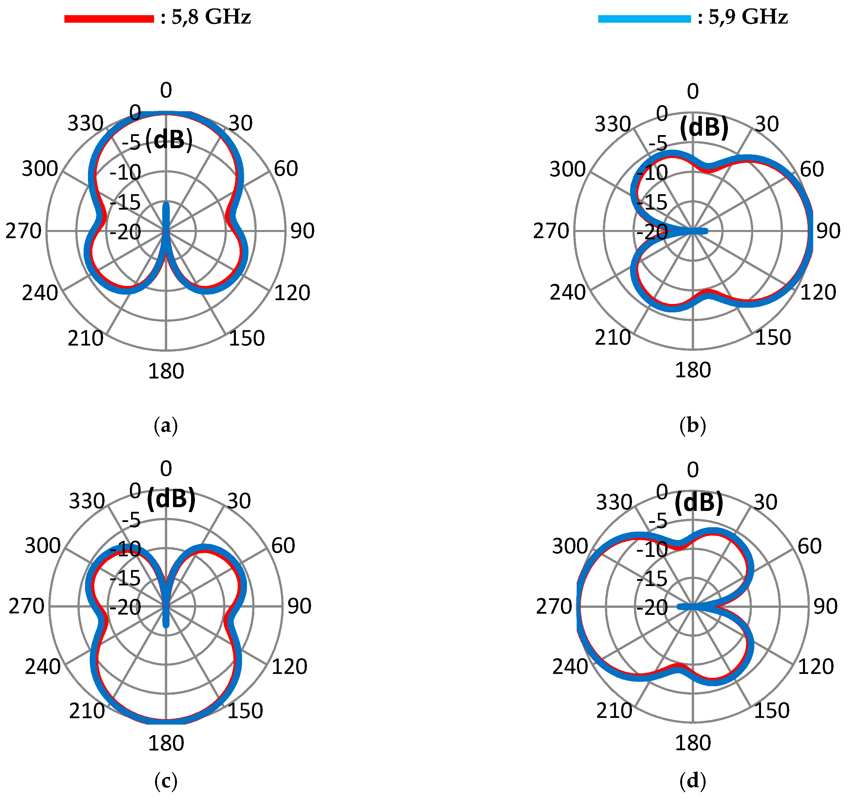
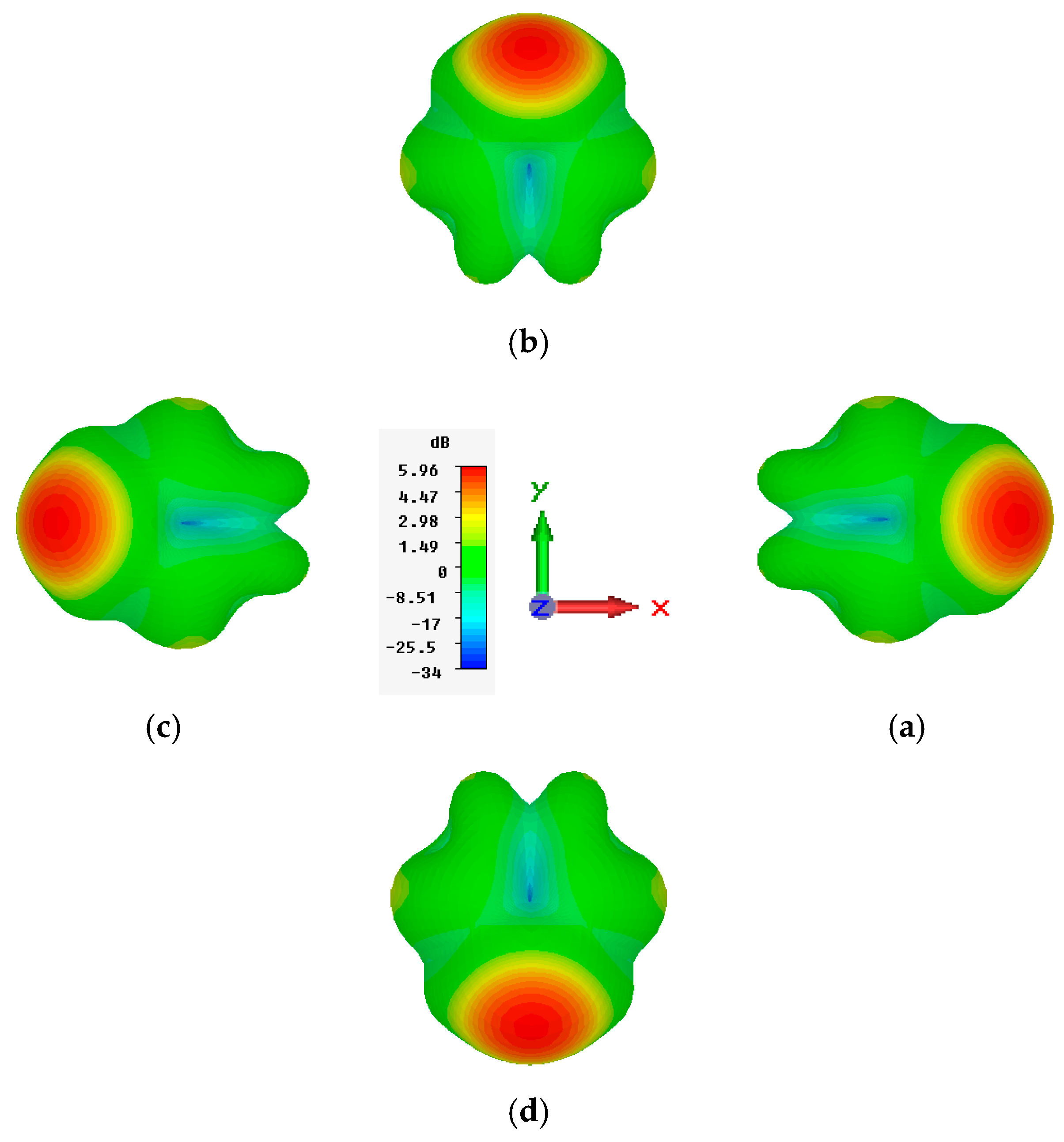
Far-field radiation patterns of the proposed antenna are simulated using an electromagnetic simulator. Figure 8a–d show the simulated radiation patterns in the azimuth plane (XOY plane). The main beam of the proposed antenna can be steered to approximate ϕ = 0°, ϕ = 90°, ϕ = 180° and ϕ = 270°, for State 1 to State 4, respectively. The radiation patterns in elevation are similar and the main beam directions all point at θ = 36°. Far-field radiation patterns at frequencies 5.8 GHz and 5.9 GHz in the azimuth plane show that the proposed wideband reconfigurable pattern antenna radiates in four different directions as shown in Figure 8 and Figure 9.
To validate the proposed design, Table 3 presents a comparison between our wideband reconfigurable antenna and other previously reported designs. It is clear that the impedance bandwidth of this antenna is higher than that of all published patterns reconfigurable antenna. According to Table 3, the proposed antenna not only has pattern-reconfigurability and an enhanced bandwidth, but also possesses additional advantages—notably its smaller size.

6. Conclusions

In this work, a new wideband reconfigurable radiation pattern antenna using four fan-shaped radiation elements is simulated and studied. Based on the four PIN diode biasing, the nominated antenna can operate at four basic different modes and achieve radiation pattern reconfigurable characteristics. When the operation states of the proposed antenna steer sequentially, the main radiation beam can be changed in four different directions and can cover the whole azimuth plane. The designed antenna can supply a wideband ranging from 5.31 to 6.95 GHz. As is known, this band is exactly reserved for Wi-Fi, WiMAX, ITS and C-band satellite. Therefore, the proposed design fulfills the goal of this work absolutely.

Conflicts of Interest

The authors declare no conflict of interest.

References

  1. Xie, P.; Wang, G.-M.; Li, H.-P.; Wen, T.; Kong, X. Frequency Reconfigurable Quasi-Yagi Antenna with a Novel Balun Loading Four PIN Diodes. Frequenz 2018, 72, 189–195. [Google Scholar] [CrossRef]
  2. Saeed, S.M.; Balanis, C.A.; Birtcher, C.R. Inkjet-Printed Flexible Reconfigurable Antenna for Conformal WLAN/WiMAX Wireless Devices. IEEE Antennas Wirel. Propag. Lett. 2016, 15, 1979–1982. [Google Scholar] [CrossRef]
  3. Kim, J.; Sung, Y. Dual-Band Microstrip Patch Antenna with Switchable Orthogonal Linear Polarizations. J. Electromagn. Eng. Sci. 2018, 18, 215–220. [Google Scholar] [CrossRef]
  4. Ramli, N.; Ali, M.T.; Islam, M.T.; Yusof, A.L.; Muhamud-Kayat, S. Aperture-Coupled Frequency and Patterns Reconfigurable Microstrip Stacked Array Antenna. IEEE Trans. Antennas Propag. 2015, 63, 1067–1074. [Google Scholar] [CrossRef]
  5. Nguyen-Trong, N.; Hall, L.; Fumeaux, C. A Frequency- and Polarization-Reconfigurable Stub-Loaded Microstrip Patch Antenna. IEEE Trans. Antennas Propag. 2015, 63, 5235–5240. [Google Scholar] [CrossRef]
  6. Rahmani, F.; Touhami, N.A.; Kchairi, A.B.; Taher, N. Circular Planar Antenna with Reconfigurable Radiation Pattern using PIN Diodes. Procedia Manuf. 2020, 46, 760–765. [Google Scholar] [CrossRef]
  7. Cheng, Y.-F.; Ding, X.; Wang, B.-Z.; Shao, W. An Azimuth-Pattern-Reconfigurable Antenna with Enhanced Gain and Front-to-Back Ratio. IEEE Antennas Wirel. Propag. Lett. 2017, 16, 2303–2306. [Google Scholar] [CrossRef]
  8. Li, H.; Wu, M.; Yuan, S.; Zhou, C. Design of Off-Center Fed Windmill Loop for Pattern Reconfiguration. IEEE Antennas Wirel. Propag. Lett. 2019, 18, 1626–1630. [Google Scholar] [CrossRef]
  9. Tran, H.H.; Park, H.C. Wideband Reconfigurable Antenna With Simple Biasing Circuit and Tri-Polarization Diversity. IEEE Antennas Wirel. Propag. Lett. 2019, 18, 2001–2005. [Google Scholar] [CrossRef]
  10. Liu, B.-J.; Qiu, J.-H.; Wang, C.-L.; Li, G.-Q. Pattern-Reconfigurable Cylindrical Dielectric Resonator Antenna Based on Parasitic Elements. IEEE Access 2017, 5, 25584–25590. [Google Scholar] [CrossRef]
  11. Jin, G.; Li, M.; Liu, D.; Zeng, G. A Simple Planar Pattern-Reconfigurable Antenna Based on Arc Dipoles. IEEE Antennas Wirel. Propag. Lett. 2018, 17, 1664–1668. [Google Scholar] [CrossRef]
  12. Chen, S.-L.; Qin, P.; Lin, W.; Guo, Y. Pattern-Reconfigurable Antenna with Five Switchable Beams in Elevation Plane. IEEE Antennas Wirel. Propag. Lett. 2018, 17, 454–457. [Google Scholar] [CrossRef]
  13. Tawk, Y.; Costantine, J.; Makhlouf, F.; Nassif, M.; Geagea, L.; Christodoulou, C.G. Wirelessly Automated Reconfigurable Antenna with Directional Selectivity. IEEE Access 2017, 5, 802–811. [Google Scholar] [CrossRef]
  14. Tang, M.-C.; Zhou, B.; Duan, Y.; Chen, X.; Ziolkowski, R.W. Pattern-Reconfigurable, Flexible, Wideband, Directive, Electrically Small Near-Field Resonant Parasitic Antenna. IEEE Trans. Antennas Propag. 2018, 66, 2271–2280. [Google Scholar] [CrossRef]
  15. Ma, W.D.; Wang, G.M.; Wang, Y.W.; Zong, B.F. Compact Microstrip Antenna with Pattern-Reconfigurable Characteristic. Radioengineering 2017, 26, 662–667. [Google Scholar] [CrossRef]
  16. Khan, M.S.; Iftikhar, A.; Capobianco, A.-D.; Shubair, R.M.; Ijaz, B. Pattern and frequency reconfiguration of patch antenna using PIN diodes. Microw. Opt. Technol. Lett. 2017, 59, 2180–2185. [Google Scholar] [CrossRef]
  17. He, X.; Gao, P.; Zhu, Z.; You, S.; Wang, P. A flexible pattern reconfigurable antenna for WLAN wireless systems. J. Electromagn. Waves Appl. 2019, 33, 782–793. [Google Scholar] [CrossRef]
  18. Rahmani, F.; Touhami, N.A.; Kchairi, A.B.; Taher, N.; El Ouahabi, M. Reconfigurable Radiation Pattern Antenna Using Kite-Shaped Parasitic Patches for Wireless Access Applications. Int. J. Microw. Opt. Technol. 2020, 15, 187–195. [Google Scholar]
  19. Deng, W.-Q.; Yang, X.-S.; Shen, C.-S.; Zhao, J.; Wang, B.-Z. A Dual-Polarized Pattern Reconfigurable Yagi Patch Antenna for Microbase Stations. IEEE Trans. Antennas Propag. 2017, 65, 5095–5102. [Google Scholar] [CrossRef]
  20. Datasheet of Microsemi MPP4203 PIN Diodes. Available online: http://www.microsemi.com (accessed on 1 March 2020).
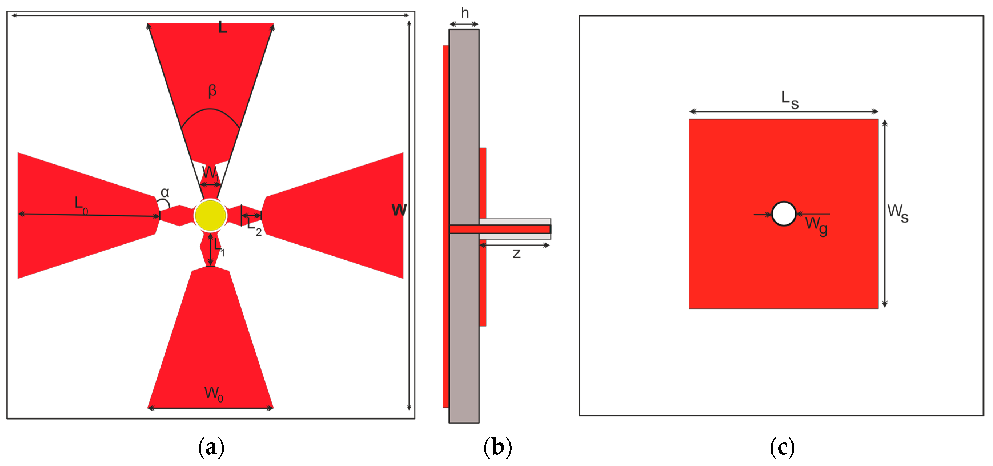
Figure 1. The designed reconfigurable antenna: (a) Top view; (b) side view; (c) bottom view.
Proceedings 63 00036 g001
Figure 2. The proposed enlarged antenna center: Top view.
Proceedings 63 00036 g002
Figure 3. Design evolution of the proposed antenna: (a) initial antenna; (b) Improved antenna design 1; (c) Improved antenna design 2; (d) Final antenna.
Proceedings 63 00036 g003
Figure 4. Simulated reflection coefficient and max gain of different antennas: (a) Reflection coefficient, (b) Max gain.
Proceedings 63 00036 g004
Figure 5. Simulated reflection coefficient and max gain versus the length L0: (a) Reflection coefficient, (b) Max gain.
Proceedings 63 00036 g005
Figure 6. Simulated reflection coefficient and max gain versus the angle β: (a) Reflection coefficient, (b) Max gain.
Proceedings 63 00036 g006
Figure 7. Simulated reflection coefficient S11 (dB).
Proceedings 63 00036 g007
Figure 8. Simulated radiation patterns of the proposed wideband reconfigurable antenna in azimuth Plane: (a) State 1, (b) State 2, (c) State 3, (d) State 4.
Proceedings 63 00036 g008
Figure 9. Simulated 3D radiation patterns at 5.8 GHz: (a) State 1, (b) State 2, (c) State 3, (d) State 4.
Proceedings 63 00036 g009
Table 1. Dimensions of the proposed antenna.
ParameterWW0W1WCWSWgLL0
Dimension30 mm20.2 mm3 mm4.4 mm34 mm4.1 mm30 mm21 mm
L1L2LCLSzhβα
4.5 mm2.8 mm4.95 mm34 mm5 mm0.8 mm40°90°
Table 2. The antenna operating states.
Operating StatesPIN Diode 1PIN Diode 2PIN Diode 3PIN Diode 4
State 1ONONOFFON
State 2ONONONOFF
State 3OFFONONON
State 4ONOFFONON
Table 3. Comparison between recently proposed antennas and the proposed wideband reconfigurable antenna.
Ref. No.Impedance$Bandwidth|S11| (dB)Peak GainAzimuth Plane Beam-ScanningSwitch No.Size (λ0*)
[7]18.6%226~6.5 dBi 360°41.37 × 1.37 × 0.02
[18]4.7%408.22 dB360°40.94 × 0.94 × 0.03
[19]5.6%204.7~7.3 dBi180°81.17 × 1.17 × 0.08
This work26.7%235.95 dB360°41.14 × 1.14 × 0.01
λ0* is the wavelength of the free space.
Publisher’s Note: MDPI stays neutral with regard to jurisdictional claims in published maps and institutional affiliations.