Proceeding Paper

Matlab Framework for Image Processing and Feature Extraction Flexible Algorithm Design †

Faculty of Engineering, Department of Industrial Engineering and Management, University of Medicine, Pharmacy, Sciences and Technology “George Emil Palade” of Targu Mures, 540142 Targu Mures, Romania
Presented at the 14th International Conference on Interdisciplinarity in Engineering—INTER-ENG 2020, Târgu Mures, , Romania, 8–9 October 2020.
Proceedings 2020, 63(1), 72; https://doi.org/10.3390/proceedings2020063072
Published: 24 January 2021

Abstract

:
Image processing and the analysis of images in order to extract relevant data is an ever-growing topic of research. Although there are numerous methods readily available, the task of image preprocessing and feature extraction requires developing specific algorithms for specific problems by combining different functions and tweaking their parameters. This paper proposes a framework that allows the flexible construction of image processing algorithms. Its user interface and architecture are designed to ease and speed up the process of algorithm creation and testing as well as serve as an application for the use of these algorithms by end users. The framework was built in Matlab and makes use of its integrated Image Processing toolbox.

1. Introduction

Enhancing and extracting useful information from digital images plays an important role in most scientific and engineering fields. There are numerous tools and software packages available for pure image processing. However, feature extraction requires the development of specific algorithms depending on image particularities and the type of data that needs to be retrieved from the images. Matlab is the leading platform for technical computing and is one of the most widely used languages for the creation of feature extraction algorithms. Its Image Processing toolbox [1] contains almost a thousand of the most common functions related to this field [2,3,4], allowing for the preprocessing, analysis, segmentation, registration, and postprocessing of digital images.
In addition to the core language and its plethora of toolboxes, Matlab also benefits from a very large community of programmers and researchers constantly extending its rich bank of tools and assets. They are all drawn by the versatility of the integrated computing environment, the volume of available resources, and the multitude of possibilities to share the created content with both programmers and end users, inside or outside the Matlab application. One of the methods for extending Matlab core functionality is the creation of frameworks, some based on available toolboxes, which can be used to program or solve problems in specific areas of interest, such as conducting behavioral and neuroimaging experiments [5], processing of digital elevation data [6], or the implementation of genetic algorithms for optimization problems [7].
Automatic characterization of materials and material structures is an essential tool for the speed and accuracy of their quality assessment. Algorithms such as those built for analyzing the cupping profiles of laminated wood products [8], the identification of fission gas bubbles [9], or for the extraction of information from SEM micrographs of nanotube structures [10] fall into this category. Developing, testing, tweaking, extending, and improving such algorithms is an iterative process that could be greatly sped up and eased by using a dedicated framework for flexible algorithm design.
The main drive behind building the framework proposed in this paper is the need for automatic characterization of highly ordered titanium oxide nanostructures (nanotubes/nanopores) formed on titanium-based surfaces as a result of an optimized electrochemical anodization process [11]. This technology has applications in the production of solar energy harvesting cells [12] and, most importantly, in medicine [13]. The formation of nanoscale tubes on the surfaces of dental or orthopedic implants [14] can be used as a tool for releasing drugs at the tissue level [15] and can help osteogenesis at the bone-implant interface for a better osseointegration of the implants [16]. The size, shape, and uniformity of nanotubes are important factors that determine the nanolayer quality and its capacity to favor osseointegration; thus, accurately extracting and interpreting these data from associated digital images is an essential process.

2. Materials and Methods

The framework for Image Processing Algorithm Design (IPADesign) was built with the nanotube micrograph interpretation in mind such as to allow the development and inclusion of most processing scenarios for this particular application. However, its structure was designed for maximum flexibility and should be suitable for most other feature extraction algorithms. This section describes the architecture of the framework and its underlying data while the next section deals with the graphical user interface and the actual implementation in Matlab.
The framework consists of a graphical user interface, part of which is dynamically generated; the engine running the algorithms; a base abstract class used to derive the classes encapsulating image processing functionality; and a number of predefined such classes (IPAFunctions) implementing the most common functions.
The general structure of the application and its associated files is schematized in Figure 1. The data it uses is grouped into 3 categories: metadata, document data, and algorithm data.
The metadata are the data used to keep track of the dynamic part of the user interface, the settings of the application, and the list of folders containing files associated with the framework. Only part of these data is saved and thus is persisted between sessions.
The document data are the structure and all the data associated with a specific image processing problem. They contain the original image or images requiring processing and a collection of up to 4 algorithm structures. These are each composed of an object containing algorithm data and a cell array with processed images from all intermediate steps. In a typical scenario, only one image will be processed with a single algorithm. However, it is possible to load more original images for batch processing or to be used in functions requiring multiple image input. At the same time, a document allows for working with more algorithms at once for comparison purposes or even have the same algorithm cloned in order to assess in parallel the intermediate results obtained during its execution. The data of a document can be saved as a workspace (.mat file) and later reloaded in the application for editing. Alternatively, the workspace can be loaded in Matlab and analyzed or postprocessed outside the application.
The algorithm data are all the information associated with a developed algorithm and can be saved separately as a workspace (.mat file) or loaded in a document. They contain all data required to build an image processing procedure but do not hold any information about the actual processed images. An algorithm consists of a succession of steps, each representing a certain image processing transformation or inquiry. A step has three properties that define how it will be treated by the algorithm running engine:
  • Tag: unique identifier of a step, typically the name of the function associated with this step, followed by a numeric index accounting for possible multiple uses of the same function;
  • Active: a Boolean (true/false) value indicating if this step is to be considered or not when running the algorithm (to allow maximum flexibility in testing algorithms);
  • InParamLinks: a list of strings linking this step function’s parameters to values returned by functions in previous steps, wherever the case (not a typical situation, but implemented for flexibility).
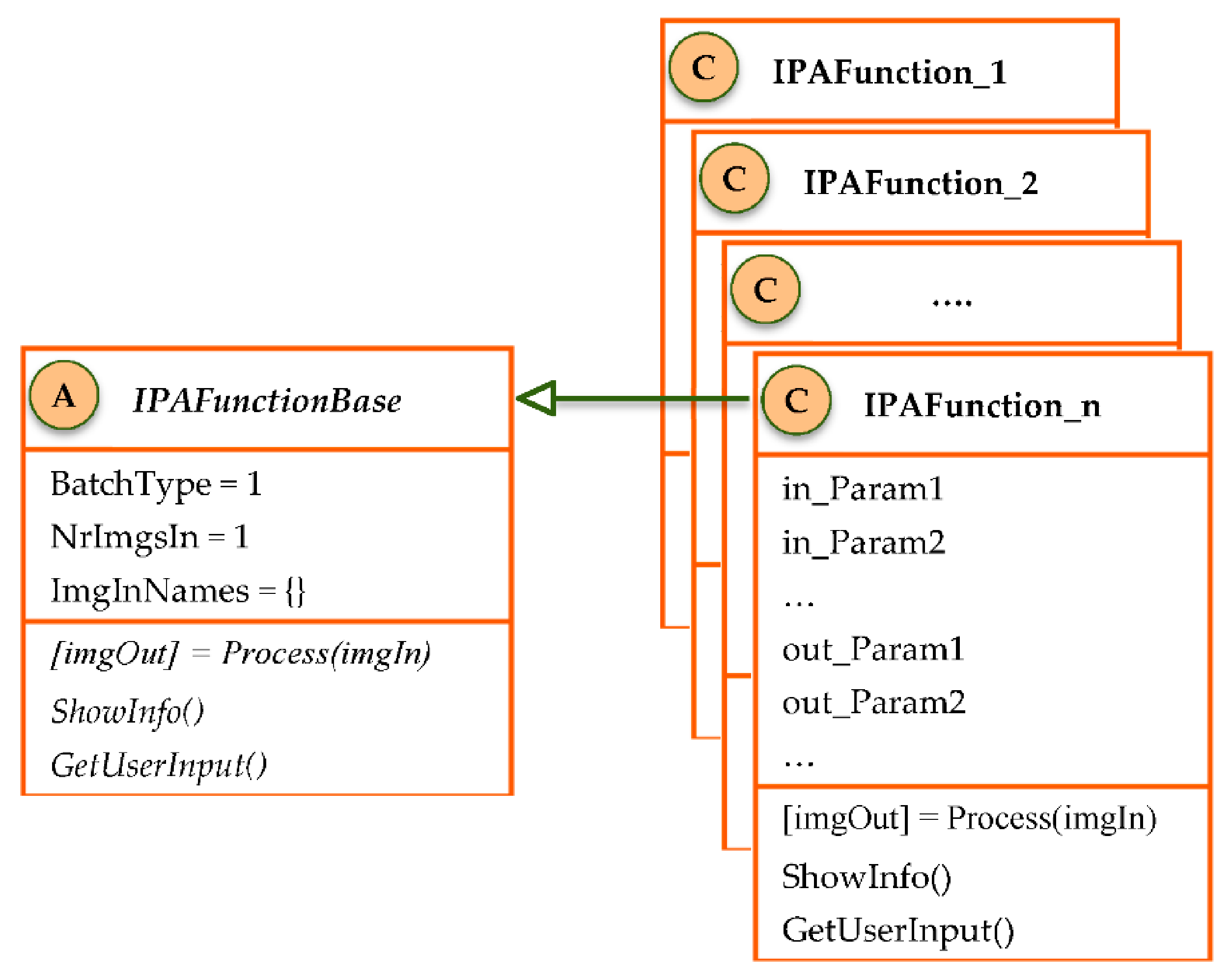
The most important component of a step is the actual image processing function. This part of the framework was implemented using the Object Oriented Programming paradigm. Each function is encapsulated in a class inheriting from an abstract class (IPAFunctionBase) as shown on Figure 2.
The abstract class has the role of a template, allowing the algorithm running engine to communicate with the image processing functions using an agreed communication protocol. It consists of 3 properties:
  • BatchType (ReadOnly): the default value (1) indicates the function will treat input images as a batch, processing each of them separately. A value of 2 should be set in the derived classes for the functions that aggregate all input functions and return a single output.
  • NrImgsIn (ReadOnly): number of image inputs. The default value of 1 means the function processes images resulted from only 1 of the previous steps (or the original images), while greater values can be used in cases where input images originate from multiple previous steps.
  • ImgInNames: a list of strings containing the tag(s) of the previous step(s) providing the input images. It should have a number of elements equal to NrImgsIn or be empty. If empty, the engine assumes only 1 input image, the one provided by the previous step (most common scenario).
and 3 methods:
  • Process: abstract method that needs to be overridden in the derived classes, implementing the logic of the image processing function. It has only 1 argument, the input image(s), and 1 output, the processed image(s). Possible additional arguments and results are implemented in the derived classes as public properties.
  • ShowInfo: implemented in derived classes only in the case of functions returning information other than images. It typically outputs feature extraction data in a visual form (GUI, graphs). It can optionally be called by the Process method to show the information when the algorithm runs; however, it is a separate method and can be accessed from the application GUI at any time.
  • GetUserInput: used in the case of functions requiring the user to provide coordinates of points from the original image(s). Useful for functions extracting scale data from images providing such information and in some other fringe scenarios.
All classes implementing image processing or feature extraction functionality need to inherit from the IPAFunctionBase abstract class. NrInImage and BatchType have to be set in the constructor if they have other values than the default (1 for both). Besides overriding the main method (Process) and possibly the other 2 methods, the class can define additional parameters in the form of public properties. By convention, these are grouped into 2 categories and should follow the following name conventions:
  • in_ParamName parameters: properties whose names begin with the “in_” particle are considered input arguments for the image processing function. These can be set on the app GUI at algorithm construction time.
  • out_ParamName parameters: properties whose names begin with the “out_” particle are results returned by the function other than images. They can be end results (feature extraction information) or intermediate data used by the “in_” parameters of subsequent steps.
For maximum flexibility, the Step field of a given step can either be an instance of an image processing class or, alternatively, it can simply contain Matlab code (FreeCode) that will be executed by the engine. This can be a series of commands separated by semicolons (;) or the name of a script to be called.

3. Results and Discussion

The framework is implemented in Matlab as an application that can be used directly as it is or extended with more image processing functionality by complying to the framework’s structure and tools. The abstract class along with the derived classes implementing core image processing functions are stored in a subfolder of the application called IPAFunctions. Classes specific to certain problems can be added and stored in different locations. The application keeps a list of paths where these classes are located, similar to Matlab’s built-in search paths. When building an algorithm, the user can choose from the list of all available image processing classes in the specified locations.
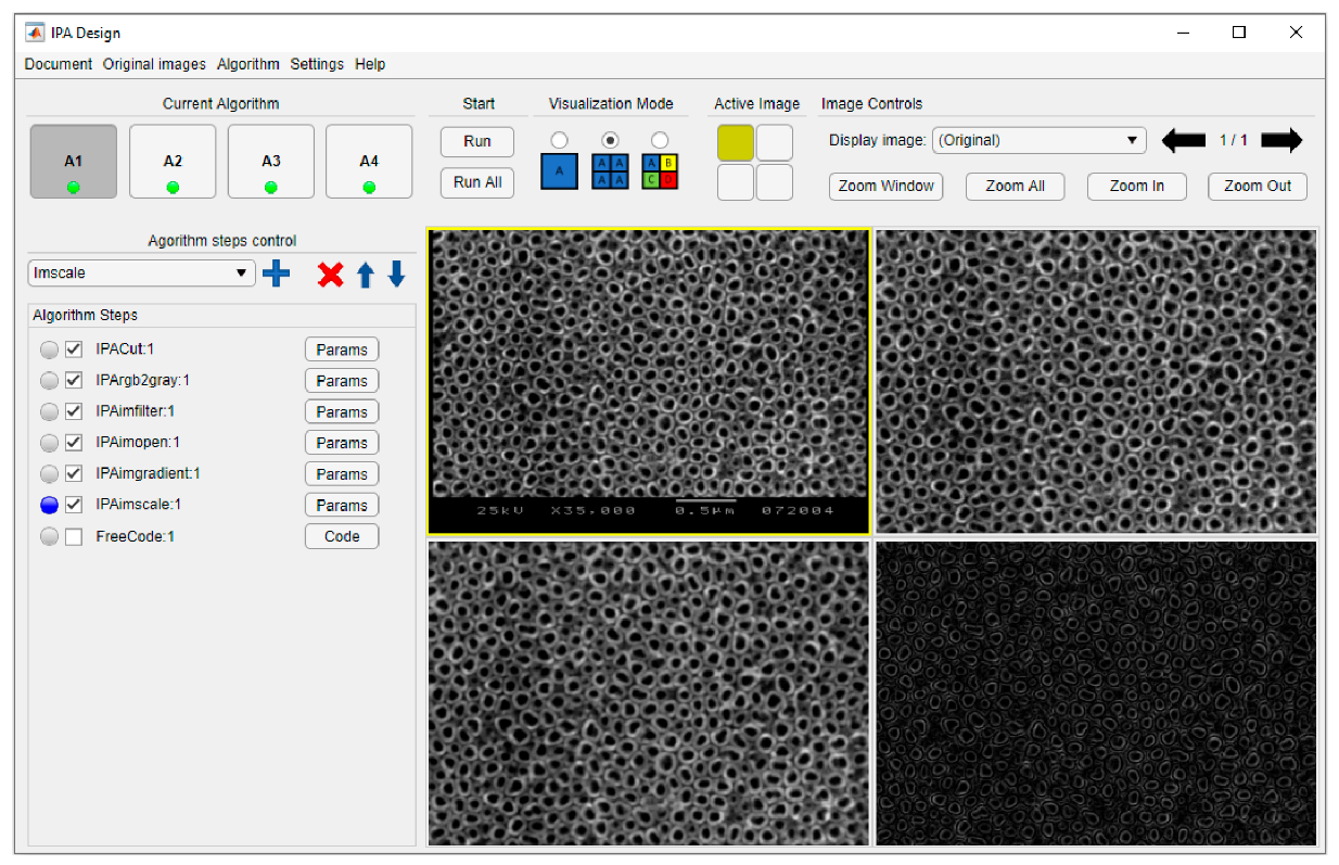
The graphical user interface (GUI) presented in Figure 3 consists of three main parts:
  • Tools area. Fixed interface area with menus and controls for all operations except algorithm creation: saving and loading documents and algorithms, managing function paths, running algorithms, and controlling and navigating the image display area.
  • Algorithm area. Dynamically generated and managed part of the interface, consisting of a list of controls associated with algorithm steps. Each line contains a control for the selection of the step, a checkbox associated with the Active field, a static text specifying the tag of the step (containing the name of the associated class), and a button opening the parameters window. Steps can be added, deleted, or reordered using the controls in the upper area.
  • Image display area. Main panel for displaying the original and transformed images. It can show a single image belonging to the active algorithm, four images from different steps of the active algorithm, or four images from specified steps on each of the four algorithms in a document.
For each step of the algorithm, the class parameters are specified in a dedicated window (Figure 4), accessed via the respective buttons as depicted in Figure 3. The parameters window is generated dynamically by the application. Depending on the NrImgsIn property of the respective class, the window offers a number of drop-down controls listing all previous tags for choosing the steps providing input images for this step. The chosen values are saved in the ImgInNames property of the class. The default value (previous step) is for the most common case when the input image is taken from the previous step, no matter which function that represents. In this case, ImgInNames is left empty. Below the choice of input images, the window lists all “in_” parameters. The user can set static values for the parameters, enter expressions to be evaluated at run time (by convention, the engine treats the entered text as an expression if it starts with the equal sign “=”), or choose from the “out_” parameters of previous steps (this is recorded as an entry in the InParamLinks field of the Step object). At the bottom of the window, two buttons allow the user to call the class methods to visually show the results (only available after running the algorithm) and to obtain user input.
In addition to the main graphical interface and the parameters dialogs, each image processing function has the option to output its specific results in a distinct window by overriding the ShowInfo method of the base abstract class. This functionality can be accessed from the parameter window of a step by clicking the respective button (shown in Figure 4).
An algorithm can be tested or used at any time by accessing the Run (current algorithm) or Run all (all algorithms in document) buttons. This will trigger the main engine of the framework, which uses all setup steps and parameter data, along with the associated files to output all intermediate and final results—images and extracted information. The images are shown in the image display area and can be navigated with the respective GUI buttons while the non-image data can be visualized or exported using the ShowInfo method.

4. Conclusions and Further Research

The framework described in this paper can be a useful tool in the development of image processing and feature extraction algorithms, offering a flexible environment for speeding up the design, testing, and ultimate use of such algorithms. It was created to cover most scenarios involved in the automatic characterization of nanotube layers, but the generality of its architecture makes it a suitable tool for most other image processing applications.
Besides its core functionality, the framework’s versatility also depends on the number of available classes. Each such class implements a specific image processing function, either from Matlab’s dedicated toolbox or user-defined. The framework’s repository of classes can easily be extended by deriving from the abstract base class. This establishes the template, ensuring compatibility between new content and the algorithm running engine.
The user interface and application structure were designed to ensure maximum flexibility in the addition of new components, the construction of algorithms, and their use by final users. However, this power and flexibility comes with an overhead in execution time. The implication of running the algorithms from a superior programming layer was not studied in this paper. Although the extra computational effort introduced by the application itself should not have a significant weight compared to the execution time of the computationally intensive image processing functions themselves, a further study could establish the actual relative impact of the extra added layer.
The main purpose for creating the framework is its use in the assessment of TiO2 nanotube structure quality by extracting statistical data regarding nanotube uniformity, shape, and size from SEM micrographs. Future research will focus on the issue of developing, testing, tweaking, and improving algorithms that can optimally achieve this task.

Funding

This research was supported by the University of Medicine, Pharmacy, Science and Technology “George Emil Palade” of Târgu Mureș, research grant number 292/2/14.01.2020.

Acknowledgments

The author would like to thank the University of Medicine, Pharmacy, Sciences and Technology “George Emil Palade” of Targu Mures and the team involved in researching the production of nanostructures on titanium-based surfaces. The idea and resources for this paper are based on the work and results of this team. A special mention goes to its leader, Strnad Gabriela, for her vision and support.

Conflicts of Interest

The author declares no conflict of interest. The funders had no role in the design of the study; in the collection, analyses, or interpretation of data; in the writing of the manuscript; or in the decision to publish the results.

References

  1. The MathWorks, I. MATLAB Image Processing Toolbox (R2019a), Natick, MA, USA. Available online: https://www.mathworks.com/products/image.html (accessed on 20 June 2020).
  2. Gonzalez, R.C.; Woods, R.E. Digital Image Processing, 4th ed.; Pearson: New York, NY, USA, 2018. [Google Scholar]
  3. Nixon, M.S.; Aguado Gonzalez, A.S. Feature Extraction & Image Processing for Computer Vision, 4th ed.; Academic Press: London, UK, 2020. [Google Scholar]
  4. Petrou, M.M.P.; Petrou, C. Image Processing: The Fundamentals, 2nd ed.; John Wiley & Sons Ltd.: Chichester, UK, 2010. [Google Scholar]
  5. Schwarzbach, J. A simple framework (ASF) for behavioral and neuroimaging experiments based on the psychophysics toolbox for MATLAB. Behav. Res. 2011, 43, 1194–1201. [Google Scholar] [CrossRef] [PubMed] [Green Version]
  6. Pan, F.; Xi, X.; Wang, C. A MATLAB-based digital elevation model (DEM) data processing toolbox (MDEM). Environ. Model. Softw. 2019, 122, 104566. [Google Scholar] [CrossRef]
  7. Cazacu, R.; Grama, L.; Mocian, I. An OOP MATLAB Extensible Framework for the Implementation of Genetic Algorithms. Part I: The Framework. Procedia Technol. 2015, 19, 193–200. [Google Scholar]
  8. Li, L.; Gong, M.; Chui, Y.H.; Schneider, M. A MATLAB-based image processing algorithm for analyzing cupping profiles of two-layer laminated wood products. Measurement 2014, 53, 234–239. [Google Scholar] [CrossRef]
  9. Collette, R.; King, J.; Keiser, D.; Miller, B.; Madden, J.; Schulthess, J. Fission gas bubble identification using MATLAB’s image processing toolbox. Mater. Charact. 2016, 118, 284–293. [Google Scholar] [CrossRef]
  10. Caudrová Slavíková, P.; Mudrová, M.; Petrová, J.; Fojt, J.; Joska, L.; Procházka, A. Automatic characterization of titanium dioxide nanotubes by image processing of scanning electron microscopic images. Nanomater. Nanotechnol. 2016, 6. [Google Scholar] [CrossRef] [Green Version]
  11. Strnad, G.; Cazacu, R.; Chetan, P.; German-Sallo, Z.; Jakab-Farkas, L. Optimized anodization setup for the growth of TiO2 nanotubes on flat surfaces of titanium based materials. MATEC Web Conf. 2017, 137, 02011. [Google Scholar] [CrossRef] [Green Version]
  12. El Ruby Mohamed, A.; Rohani, S. Modified TiO2 nanotube arrays (TNTAs): Progressive strategies towards visible light responsive photoanode, a review. Energy Environ. Sci. 2011, 4, 1065–1086. [Google Scholar] [CrossRef]
  13. Ribeiro, A.; Gemini-Piperni, S.; Alves, S.A. Titanium dioxide nanoparticles and nanotubular surfaces: Potential applications in nanomedicine. In Metal Nanoparticles in Pharma, 1st ed.; Rai, M., Shegokar, R., Eds.; Springer International Publishing: Basel, Switzerland, 2017; pp. 101–121. [Google Scholar]
  14. Strnad, G.; Portan, D.; Jakab-Farkas, L.; Petrovan, C.; Russu, O. Morphology of TiO2 surfaces for biomedical implants developed by electrochemical anodization. Mater. Sci. Forum 2017, 907, 91–98. [Google Scholar] [CrossRef]
  15. Gulati, K.; Saso, I. Dental implants modified with drug releasing titania nanotubes: Therapeutic potential and developmental challenges. Expert Opin. Drug Deliv. 2017, 14, 1009–1024. [Google Scholar] [CrossRef] [PubMed]
  16. Gulati, K.; Maher, S.; Findlay, D.; Losic, D. Titania nanotubes for orchestrating osteogenesis at the bone–implant interface. Nanomed. J. 2016, 11, 1847–1864. [Google Scholar] [CrossRef] [PubMed] [Green Version]
Figure 1. Application architecture and its associated files.
Proceedings 63 00072 g001
Figure 2. Diagram of the abstract base image processing function class and its derived classes.
Proceedings 63 00072 g002
Figure 3. Main GUI of the application. Tools area—upper zone; algorithm area—left, image display—right.
Proceedings 63 00072 g003
Figure 4. Example of a “Parameters” window.
Proceedings 63 00072 g004
Publisher’s Note: MDPI stays neutral with regard to jurisdictional claims in published maps and institutional affiliations.