Fully Printed Wearable Electrode Textile for Electrotherapy Application †


Abstract
:1. Introduction
2. Materials
3. Methods
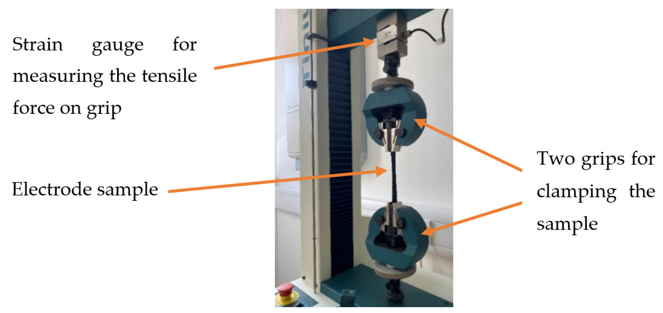
3.1. Tensile Test
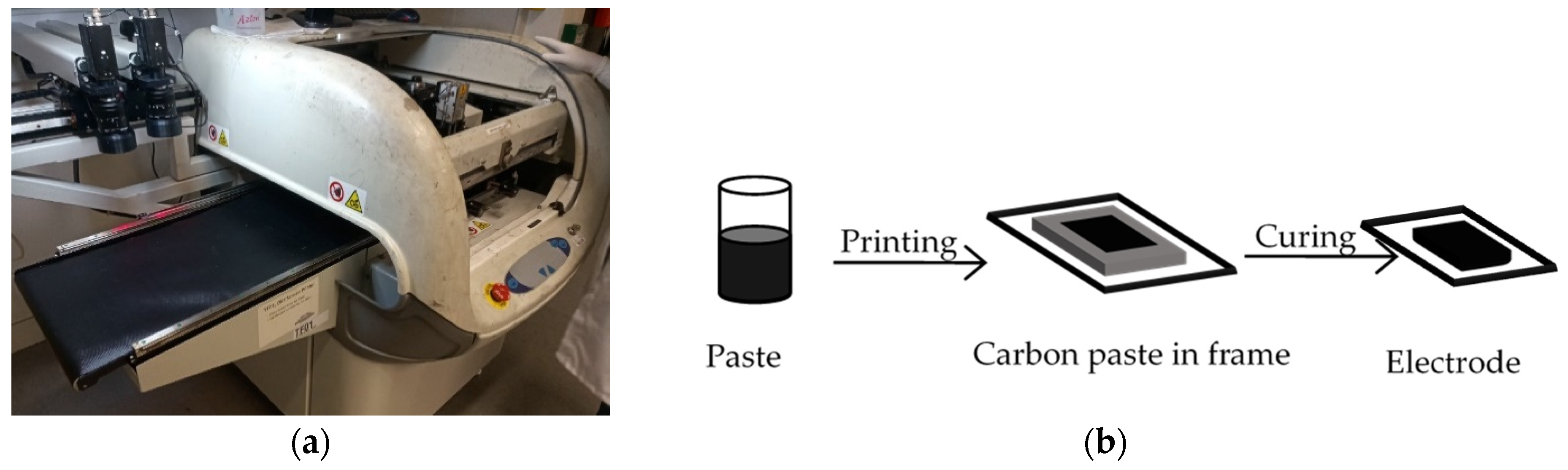
3.2. Printing Method
4. Results and Discussion
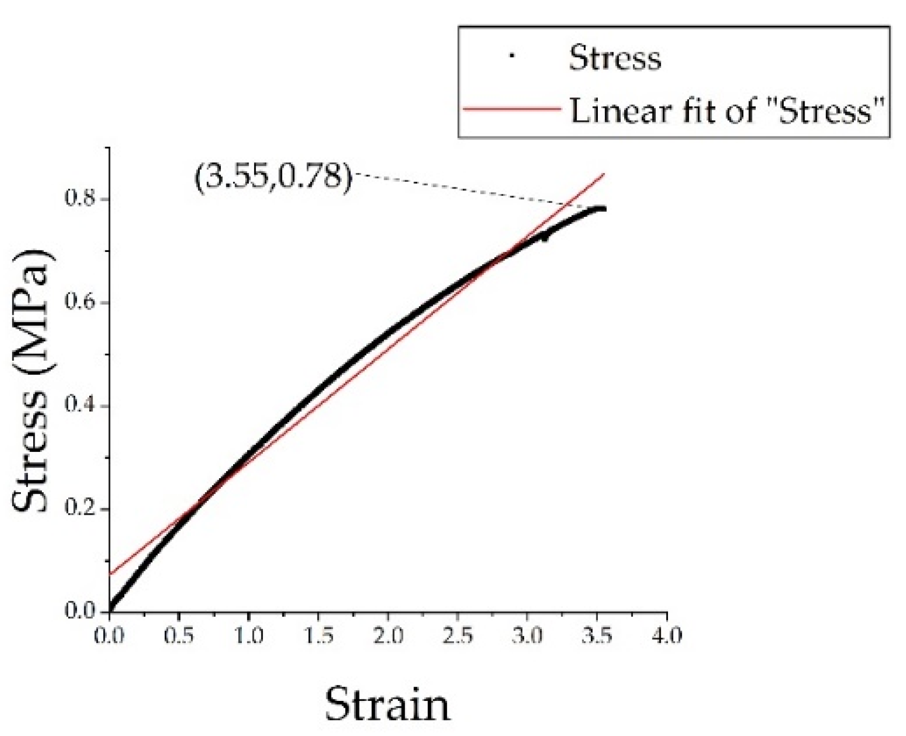
4.1. Tensile Test
4.2. Electrode Textile
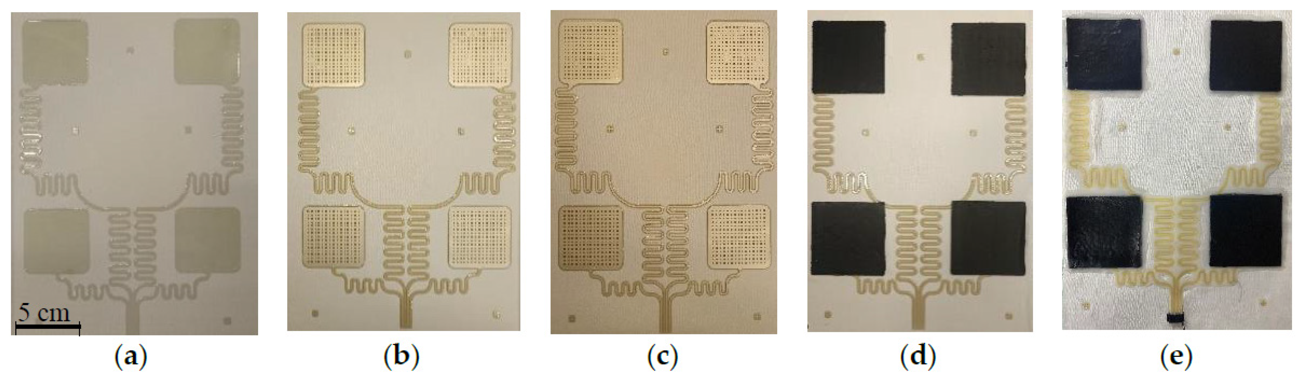
4.2.1. Fabrication Process
- (1)
- Interface layer to create a smooth and flexible surface on which the silver paste can be printed (Figure 4a). The interface layer was formed using two prints of Fabink IF-UV-1039 followed one print of Fabink IF-UV-1004. The Fabink IF-UV-1039 provides a waterproof layer and the Fabink UV-IF-1004 creates a smooth surface with good adhesion to the silver layer. Ultraviolet (UV) curing was applied after each print by exposing the sample to a UV cabinet supplied by UV Light Technology Ltd. (Birmingham, UK). The UV curing time was 60 s for Fabink IF-UV-1039 and 30 s for Fabink IF-UV1004.
- (2)
- Conductive silver layer to create the conductive tracks and conductive grid patterns shown in Figure 4b. The conductive layer was formed using one print of Fabink TC-C4007. The paste was cured in a box oven at 130 °C for 25 min.
- (3)
- Encapsulation layer printing to create a protective layer for the conductive tracks (Figure 4c). The encapsulation layer was formed using one print of Fabink IF-UV1004 followed by two prints of Fabink IF-UV-1039. Curing time was the same as those used in the interface layer.
- (4)
- Carbon rubber layer to provide an interface between the conductive pads and the skin (Figure 4d). The electrode layer was directly printed on top of conductive grid patterns using stencil printing. The electrode paste was cured in a box oven at 80 °C for 30 min.
- (5)
- Rubber layer printing around the electrode edges and silver tracks to provide electrode adhesion to the fabric and protect the conductive tracks (Figure 4e). The rubber layer was printed by hand with a syringe and cured in a box oven at 80 °C for 20 min.
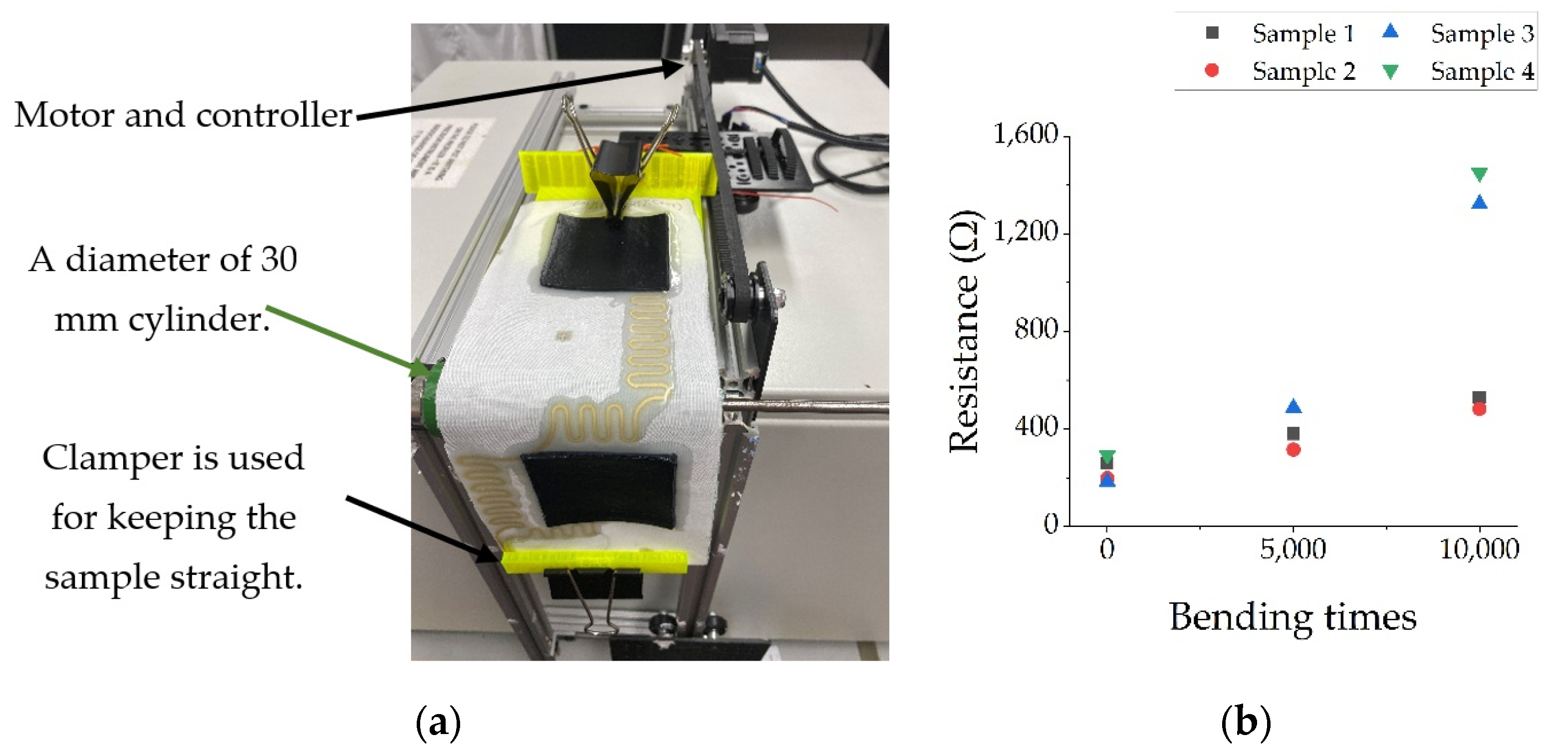
4.2.2. Durability Test
5. Conclusions and Future Work
Author Contributions
Funding
Institutional Review Board Statement
Informed Consent Statement
Data Availability Statement
Conflicts of Interest
References
- Osteoarthritis in General Practice—Data and Perspectives—Arthritis Research UK. 2013. Available online: https://www.bl.uk/collection-items/osteoarthritis-in-general-practice-data-and-perspectives (accessed on 5 November 2020).
- Liu, M.; Beeby, S.; Yang, K. Electrode for Wearable Electrotherapy. Proceedings 2019, 32, 5. [Google Scholar] [CrossRef]
- Yang, K.; Meadmore, K.; Freeman, C.; Grabham, N.; Hughes, A.M.; Wei, Y.; Torah, R.; Glanc-Gostkiewicz, M.; Beeby, S.; Tudor, J. Development of User-Friendly Wearable Electronic Textiles for Healthcare Applications. Sensors 2018, 18, 2410. [Google Scholar] [CrossRef] [PubMed]
- Liu, M.; Ward, T.; Young, D.; Matos, H.; Wei, Y.; Adams, J.; Yang, K. Electronic textiles based wearable electrotherapy for pain relief. Sens. Actuators A Phys. 2019, 111701. [Google Scholar] [CrossRef]
- Pawlaczyk, M.; Lelonkiewicz, M.; Wieczorowski, M. Age-dependent biomechanical properties of the skin. Adv. Dermatol. Allergol. 2013, 5, 302–306. [Google Scholar] [CrossRef] [PubMed]

| Pastes | Functionality |
|---|---|
| Fabink UV-IF-1004 | Standard interface to create smooth surface on various fabrics |
| Fabink UV-IF-1039 | Waterproof interface and encapsulation suitable for various fabrics |
| Fabink TC-C4007 | Silver ink for printing flexible conductive layer on top of the interface layer |
| Fabink E-0002 | Carbon rubber paste for soft and tacky (but not sticky) electrode |
| Binder material of the novel electrode paste | Rubber to protect silver tracks and improve the electrode–fabric adhesion |
Publisher’s Note: MDPI stays neutral with regard to jurisdictional claims in published maps and institutional affiliations. |
© 2021 by the authors. Licensee MDPI, Basel, Switzerland. This article is an open access article distributed under the terms and conditions of the Creative Commons Attribution (CC BY) license (https://creativecommons.org/licenses/by/4.0/).
Share and Cite
Liu, M.; Glanc-Gostkiewicz, M.; Beeby, S.; Yang, K. Fully Printed Wearable Electrode Textile for Electrotherapy Application. Proceedings 2021, 68, 12. https://doi.org/10.3390/proceedings2021068012
Liu M, Glanc-Gostkiewicz M, Beeby S, Yang K. Fully Printed Wearable Electrode Textile for Electrotherapy Application. Proceedings. 2021; 68(1):12. https://doi.org/10.3390/proceedings2021068012
Chicago/Turabian StyleLiu, Meijing, Monika Glanc-Gostkiewicz, Steve Beeby, and Kai Yang. 2021. "Fully Printed Wearable Electrode Textile for Electrotherapy Application" Proceedings 68, no. 1: 12. https://doi.org/10.3390/proceedings2021068012