1. Introduction
Electrospinning is a simple, low-cost electrohydrodynamic technique to fabricate nano-sized fibers that have many promising applications in textile engineering [
1], environmental remediation [
2], energy storage devices [
3], etc. One of the most encouraging and demanding nanofiber applications is in the drug delivery area [
4,
5]—nanofibers can be used as a depo for the sustained release of many pharmaceuticals, including the biopharmaceuticals. Such drug delivery systems have been demonstrated for release of bioactive molecules in the site of the defect, as active scaffolds for tissue engineering [
6] and wound dressing [
7]. However, practical applications of electrospun fibers are often limited by the fabrication throughput, reproducibility, and uniformity of produced materials. In this work, we investigate various spinnerets that are used for high-throughput electrospinning, and evaluate the parameters that influence the electrospinning outcome.
The productivity of the classical electrospinning setup (needle connected to a high-voltage supply) is very low, leading to the nanofiber production rates between 0.1–1.0 g/h [
8]. This limits the practical applications of the technology. Multineedle and needleless approaches have been investigated for upscaling the nanofiber production. Multineedle electrospinning has been reviewed and described in detail in many recent publications [
9,
10,
11] and it is not considered in this work. Shortly, there are two big drawbacks of the multineedle approaches: first, the transport of solution to each needle at a constant flow rate that is needed for continuous and uniform fiber production and, second, the strong interactions between needles that limits high electric field homogeneity near spinning electrodes. The needle-free electrospinning is another promising technique used to fulfill large production needs. In this case, numerous liquid jets are created simultaneously from the spinneret leading to a higher throughput. While the set-up of the needle devices is simpler (requires one system for the supply of polymer solutions), a self-organized electrospinning along a free liquid surface may lead to an operation that is difficult to control.
Many parameters influence the creation of nanofibers, such as polymer and its concentration, solvents, ambient temperature/humidity, and electrode distance. Most certainly, the features of the spinning electrode surface, where the fibers formation is initiated, play a crucial role in the electrospinning process. In fact, the electric field (E) strength and distribution near the spinneret is a key to initiating and maintaining stable electrospinning. It has already been demonstrated that the geometry and dimensions of the spinneret have a strong influence on its electric field profile [
12] and various spinning electrodes exploiting features with a high-aspect ratio have been designed and tested. Despite numerous publications describing various needleless electrospinning techniques [
13,
14,
15], the comprehensive and quantitative theoretical comparison of the setups has not been reported yet.
We define two critical parameters in the development of the electrospinning setup: (i) the intensity of the electric field that determines the facility of the jet initiation—higher E magnitude results in higher liquid jet number and, in general, thinner fibers; and (ii) the uniformity of the electric field along the entire spinning surface of the electrode that affects the fibers size distribution—more uniform E leads to the formation of more uniform elements. In this paper, we evaluate these critical parameters using the models of the most promising needleless electrospinning systems with a variety of spinnerets: cylinder and wire electrode configuration, ring and spiral coil arrangements, and a slit surface. Our work presents a realistic and meaningful comparison of different spinning electrodes and suggests key design parameters for effective, high-throughput electrospinning systems. We believe that knowledge-driven design of the electrodes is an essential step towards reproducible high-throughput electrospinning and more wide-spread applications of electrospun pharmaceutical materials.
2. Methods
In order to determine the electric field profile of the spinning electrodes, three-dimensional models and simulations were prepared via COMSOL Multiphysics ver. 5.5, using the finite element method (FEM). The electric field strength distribution was specified for each system based on the characteristic relation between the electric field (
E) and the scalar electrostatic potential (φ), expressed by Equation (1):
The theoretical results were obtained at the temperature of 293 K. The voltage applied to the system was 60 kV, the electrostatic potential applied to the spinning and collecting electrodes was 30 kV and −30 kV, respectively. The distance between the electrodes was measured from the top surface of the spinneret to the bottom surface of the collector and its magnitude d = 200 mm. In all examples, the collecting surface was represented by a plate with width × depth × thickness as 160 mm × 355 mm × 2 mm, respectively. All the sides and boundaries were set as zero potential. After meshing and computing, the electric field profiles were solved by the software and their intensities were extracted for further analysis.
3. Results
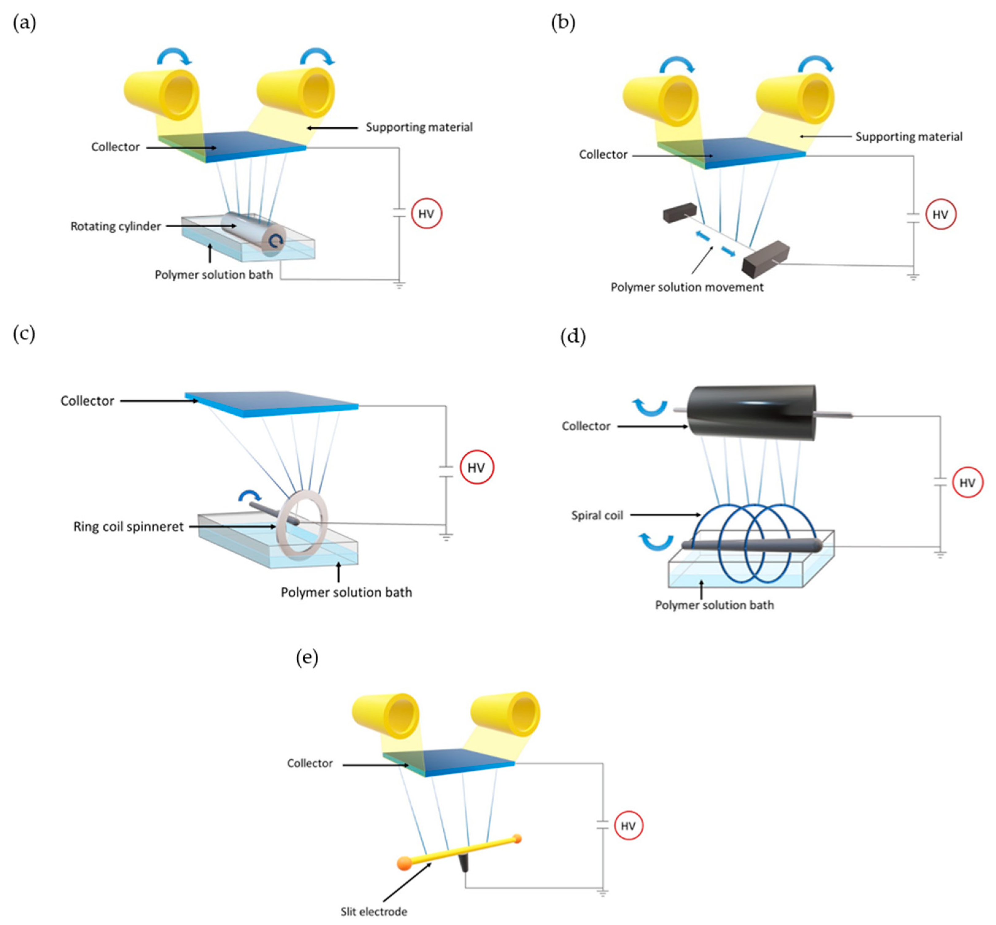
Five of the most widely reported needleless electrospinning spinnerets were considered in this study. The schematic illustrations of the setups used are depicted in
Figure 1.
Cylindrical rotating spinneret developed by Elmarco as Nanospider Technology [
16]. This is one of the most efficient electrospinning electrodes. In this setup, the polymer solution is distributed along the spinning surface from the close bath unit, minimizing undesirable evaporation of the material (
Figure 1a).
Thin metallic wire that is a new generation of Nanospider technique [
17] (
Figure 1b), where the feeding unit is a close bath moving on the spinning electrode. Both configurations are characterized by a high production rate of very thin fibers with diameter between 80 nm and 700 nm.
Ring coil as depicted in schematic representation in
Figure 1c and described in [
18]. As for the first drum Nanospider technology, the electrode is partially immersed in polymer solution bath and the slow rotation of the electrode leads to load of polymer solution on the spinneret surface.
Spiral coil—similar to the ring coil shape, but with more features (as illustrated in
Figure 1d and described in [
19]).
Slit electrode as illustrated in
Figure 1e with two plastic balls positioned at the ends of the spinneret. These balls were reported to increase the uniformity of the electric field strength along entire spinning surface [
20]. In this case, the polymer solution is introduced to the system manually via a syringe at the beginning of each spinning operation.
In order to provide a reliable comparison, in our theoretical study, only spinnerets were varied. All other parameters (electrodes distance, applied potential difference, type, and surface area of collector) were kept constant in all simulations.
3.1. Cylinder and Wire Electrodes
In this part, we simulated and compared the rotating cylinder (radius R = 25 mm and length L = 350 mm), as well as the wire (radius R = 0.25 mm and length L = 350 mm) spinnerets, interacting with the collecting surface. The electric field profile and its strength of both systems is depicted in
Figure 2. The 3D view of the cylinder-plate system (
Figure 2a) shows a strong electric field near the spinneret. Moreover, the theoretical analysis of the electrostatic charge distribution on the cylinder presents its tendency to concentrate the most at the ends of the electrode (
Figure 2b), which can be confirmed by the analytical analysis presented in
Figure 2c. The average electric field intensity along most of the spinning surface reaches 7.6 × 10
5 V/m, presenting a high uniformity in this area, but its value dramatically increases at the edges regions.
The replacement of the cylinder electrode by a very thin wire changes the electrostatic properties of the system. There is a different electric field distribution between the spinning and collecting surfaces (
Figure 2d). Similarly, as for the cylinder-plate system, the density of electric charge is greater at the sharp edges of the electrode (
Figure 2e). Along entire spinning area, the average electric field was of higher intensity (around 6.3 × 10
6 V/m at the most part of the spinning edge), compared to the cylinder.
3.2. Ring Coil
The theoretical model presented in this section consists of a metallic coil with a major radius R = 40 mm and a minor radius r = 1 mm. As shown in
Figure 3a, the electric field is the most intense around the spinneret and the highest density of electric charge is observed at the top part of the electrode (indicated by a white arrow in
Figure 3b). The tendency of the electric charge to concentrate mostly in this area can be verified by analytical description. Indeed, the electric field plotted along the coil axis direction takes a form of sharp peak with a magnitude of 5.2 × 10
6 V/m, presenting its highest intensity in this region.
3.3. Spiral Coil
The spiral coil model analyzed below includes a spinneret with coil length, diameter, spiral distance, and wire diameter of 160 mm, 80 mm, 40 mm, and 2 mm, respectively. The theoretical analysis showed notable enhancement of electric field intensity near the spinning electrode compared to the collecting surface (
Figure 4a). Moreover, an extraordinary E distribution along the coil axis direction was observed. A significant decrease of the electric charge density at the central spinnerets, resulting in more intense electric field at the side parts (indicated by white arrows in
Figure 4b) was observed. This characteristic behavior of the electrostatic charges is also shown in
Figure 4c. The high peaks on the graph represent the electric field intensity on the top of each coil surface, where the electrospinning process is initiated. The
E values above left and right side coils slightly differ and equal to 2.49 × 10
6 V/m and 2.57 × 10
6 V/m, respectively. The electric field strengths of the coils at the center are 2.09 × 10
6 V/m, 1.89 × 10
6 V/m and 2.02 × 10
6 V/m. This shows that even distance between neighboring coils does not ensure the same electric field profile for each of them.
3.4. Slit Electrode
The effect of four different slit electrode lengths on the fiber morphology was tested by Pejchar et al. SEM analysis proved that the size of the fibers deposited on the collector does not depend significantly on the length of the slit element (the average diameter of the fabricated fibers varies from 190 nm to 280 nm), but the increase of the electrode length enhanced the production rate. We verified this experimental investigation in theory. The electric field profiles of four different spinnerets, characterized by width
× height as 4 mm and 4 mm, respectively but different lengths L, were studied and the results are presented in
Figure 5. Theoretical analysis of the electrostatic features of slit-plate configurations showed that the electric field intensity along the spinning surface is enhanced with a decrease of the spinneret length L (
Figure 5a–h). Comparing the
E distribution along the surface, where the electrospinning is initiated, a notable difference in
E uniformity was also observed. Indeed, as the opposite to the
E strength, a longer slit increases the electric field homogeneity. However, a small difference of electric field intensity may be observed near the center of spinnerets (
Figure 5i)—changing the L value gives average
E magnitudes of 4.09 × 10
6 V/m, 3.73 × 10
6 V/m, 3.49 × 10
6 V/m, and 3.14 × 10
6 V/m for L = 100 mm, L = 150 mm, L = 200 mm, and L = 300 mm, respectively.
4. Discussion
A comprehensive theoretical study of the needleless electrospinning systems, described in this paper, allowed us to visualize their electric field profile—a key for electrospinning process development. In fact, all simulated and presented above needle-free configurations are characterized by sharp edges effect, i.e., the tendency of electric charge to concentrate at the curved surface. This mechanism diminishes the electric field uniformity along the spinning region and, in practice, may lead to non-uniform fibers formation. Our FEM analysis results presented slit electrodes as good spinnerets for homogeneous
E (
Figure 5). In this case, the electric field uniformity was improved by adding the isolating elements at the ends of the electrode that minimized the electric charge there. High
E-uniformity was also seen along the spinning surface of the cylinder and thin wire (
Figure 2). Even the cross section area of the spinneret allowed an evenly distributed electric charge and thus enhanced electric field homogeneity. It has to be emphasized that besides the electric field uniformity, these systems also show the highest electric field strength near spinnerets. We suggest that equal electrical forces provided by these needleless spinnerets will result in the formation of fibers with even diameters. Additionally, due to high charge density at the surface, where the electrospinning is initiated, the process would require lower applied external potential difference and result in the creation of thinner elements.
For the ring coil (
Figure 3) and spiral coil (
Figure 4) systems, the electric field intensity differs along its surface. Due to a strong interaction with collector located above the spinneret, the electric field strength took the highest value on the top part of the coils. This led to low electric field uniformity and only allowed us to deform the polymer liquid into a jet along a very small region of the electrode. In a spiral coil arrangement, significant differences of electric field profiles were observed between coils located on the side and those positioned at the center. Higher electric field was simulated on the external spinnerets, thus the jet formation there is expected to be much easier. In order to increase the electric field uniformity along coil axis direction, i.e., enhance its magnitudes near central coils, a greater distance between them should be applied. We suggest that this strategy may minimize the strong electrostatic interaction between charges located at their surfaces and notably improve efficiency of the system.
5. Conclusions
An electric field profile of spinning surface is a key property to develop and optimize electrospinning process. The geometry and dimensions of spinneret strongly influence the efficiency of the fibers formation and have a significant impact on their features, such as diameter and uniformity. This study considered and analyzed some of the most productive needleless systems currently available on the market and extensively compared them based on two main criteria: (i) electric field strength and (ii) homogeneity. Our investigation can be used to determine the most effective electrospinning arrangements for pharmaceutical and medical application and greatly help to choose or design even more effective spinnerets.
Author Contributions
Conceptualization, A.K., A.S., and M.B.; investigation, A.K., A.S., and M.B.; writing—original draft, A.K.; writing—review and editing, A.S. and M.B., supervision, A.S. and M.B. All authors have read and agreed to the published version of the manuscript.
Acknowledgments
This work was supported by grant from the European Union (transMed; H2020-MSCA-765441).
Conflicts of Interest
The authors declare no conflict of interest.
References
- Pant, H.R.; Bajgai, M.P.; Nam, K.T.; Seo, Y.A.; Pandeya, D.R.; Hong, S.T.; Kim, H.Y. Electrospun nylon-6 spider-net like nanofiber mat containing TiO2 nanoparticles: A multifunctional nanocomposite textile material. J. Hazard. Mater. 2011, 185, 124–130. [Google Scholar] [CrossRef] [PubMed]
- Duan, Z.; Huang, Y.; Zhang, D.; Chen, S. Electrospinning Fabricating Au/TiO 2 Network-like Nanofibers as Visible Light Activated Photocatalyst. Sci. Rep. 2019, 9, 8008. [Google Scholar] [CrossRef] [PubMed]
- Sun, G.; Sun, L.; Xie, H.; Liu, J. Electrospinning of Nanofibers for Energy Applications. Nanomaterials 2016, 6, 129. [Google Scholar] [CrossRef] [PubMed]
- Kamath, S.M.; Sridhar, K.; Jaison, D.; Gopinath, V.; Ibrahim, B.K.M.; Gupta, N.; Sundaram, A.; Sivaperumal, P.; Padmapriya, S.; Patil, S.S. Fabrication of tri-layered electrospun polycaprolactone mats with improved sustained drug release profile. Sci. Rep. 2020, 10, 18179. [Google Scholar] [CrossRef] [PubMed]
- Norouzi, M.; Abdali, Z.; Liu, S.; Miller, D.W. Salinomycin-loaded Nanofibers for Glioblastoma Therapy. Sci. Rep. 2018, 8, 9377. [Google Scholar] [CrossRef] [PubMed]
- Rampichová, M.; Buzgo, M.; Lukasova, V.; Mickova, A.; Vocetkova, K.; Sovková, V.; Rustichelli, F.; Amler, E. Functionalization of 3D fibrous scaffolds prepared using centrifugal spinning with liposomes as a simple drug delivery system. Acta Polytech. Ctu Proc. 2017, 8. [Google Scholar] [CrossRef]
- Buzgo, M.; Plencner, M.; Rampichova, M.; Litvinec, A.; Prosecka, E.; Staffa, A.; Kralovic, M.; Filova, E.; Doupnik, M.; Lukasova, V.; et al. Poly-ε-caprolactone and polyvinyl alcohol electrospun wound dressings: Adhesion properties and wound management of skin defects in rabbits. Regen. Med. 2019, 14, 423–445. [Google Scholar] [CrossRef] [PubMed]
- Brown, P.J.; Stevens, K. (Eds.) Nanofibers and Nanotechnology in Textiles; Woodhead Publishing Series in Textiles; CRC Press: Boca Raton, FL, USA, 2007; ISBN 978-1-84569-105-9. [Google Scholar]
- He, J.; Zhou, Y. Chapter 6—Multineedle Electrospinning. In Electrospinning: Nanofabrication and Applications; Ding, B., Wang, X., Yu, J., Eds.; Micro and Nano Technologies; William Andrew Publishing: Norwich, NY, USA, 2019; pp. 201–218. ISBN 978-0-323-51270-1. [Google Scholar]
- Zhu, Z.; Wu, P.; Wang, Z.; Xu, G.; Wang, H.; Chen, X.; Wang, R.; Huang, W.; Chen, R.; Chen, X.; et al. Optimization of electric field uniformity of multi-needle electrospinning nozzle. Aip Adv. 2019, 9, 105104. [Google Scholar] [CrossRef]
- Xu, Y.; Li, X.; Xiang, H.-F.; Zhang, Q.-Q.; Wang, X.-X.; Yu, M.; Hao, L.-Y.; Long, Y.-Z. Large-Scale Preparation of Polymer Nanofibers for Air Filtration by a New Multineedle Electrospinning Device. Available online: https://www.hindawi.com/journals/jnm/2020/4965438/ (accessed on 29 October 2020).
- Niu, H.; Wang, X.; Lin, T. Needleless electrospinning: Influences of fibre generator geometry. J. Text. Inst. 2012, 103, 787–794. [Google Scholar] [CrossRef]
- Niu, H.; Lin, T. Fiber Generators in Needleless Electrospinning. J. Nanomater. 2012, 2012. [Google Scholar] [CrossRef]
- Partheniadis, I.; Nikolakakis, I.; Laidmäe, I.; Heinämäki, J. A Mini-Review: Needleless Electrospinning of Nanofibers for Pharmaceutical and Biomedical Applications. Processes 2020, 8, 673. [Google Scholar] [CrossRef]
- Song, J.; Kim, M.; Lee, H. Recent Advances on Nanofiber Fabrications: Unconventional State-of-the-Art Spinning Techniques. Polymers 2020, 12. [Google Scholar] [CrossRef] [PubMed]
- Jirsak, O.; Sanetrnik, F.; Lukas, D.; Kotek, V.; Martinova, L.; Chaloupek, J. Method of Nanofibres Production from a Polymer Solution Using Electrostatic Spinning and a Device for Carrying Out the Method. U.S. Patent 7,585,437, 8 September 2009. [Google Scholar]
- Yalcinkaya, F. Preparation of Various Nanofiber Layers Using Wire Electrospinning System. Arab. J. Chem. 2019, 12, 5162–5172. [Google Scholar] [CrossRef]
- Wang, X.; Wang, X.; Lin, T. 3D electric field analysis of needleless electrospinning from a ring coil. J. Ind. Text. 2014, 44, 463–476. [Google Scholar] [CrossRef]
- Wang, X.; Niu, H.; Wang, X.; Lin, T. Needleless Electrospinning of Uniform Nanofibers Using Spiral Coil Spinnerets. Available online: https://www.hindawi.com/journals/jnm/2012/785920/ (accessed on 10 July 2020).
- Pejchar, K.; Vysloužilová, L.; Pokorný, P.; Bílek, M.; Beran, J.; Lukáš, D. The Slit Needleless Electrode for the Electrospinning. In Proceedings of the 5th International Conference of Nanocon, Brno, Czech Republic, 16–18 October 2013. [Google Scholar]
| Publisher’s Note: MDPI stays neutral with regard to jurisdictional claims in published maps and institutional affiliations. |
© 2020 by the authors. Licensee MDPI, Basel, Switzerland. This article is an open access article distributed under the terms and conditions of the Creative Commons Attribution (CC BY) license (https://creativecommons.org/licenses/by/4.0/).

