
Freeform Optimization of an Ultrasonic Horn Coupled to an Airborne MEMS Transducer †


Abstract
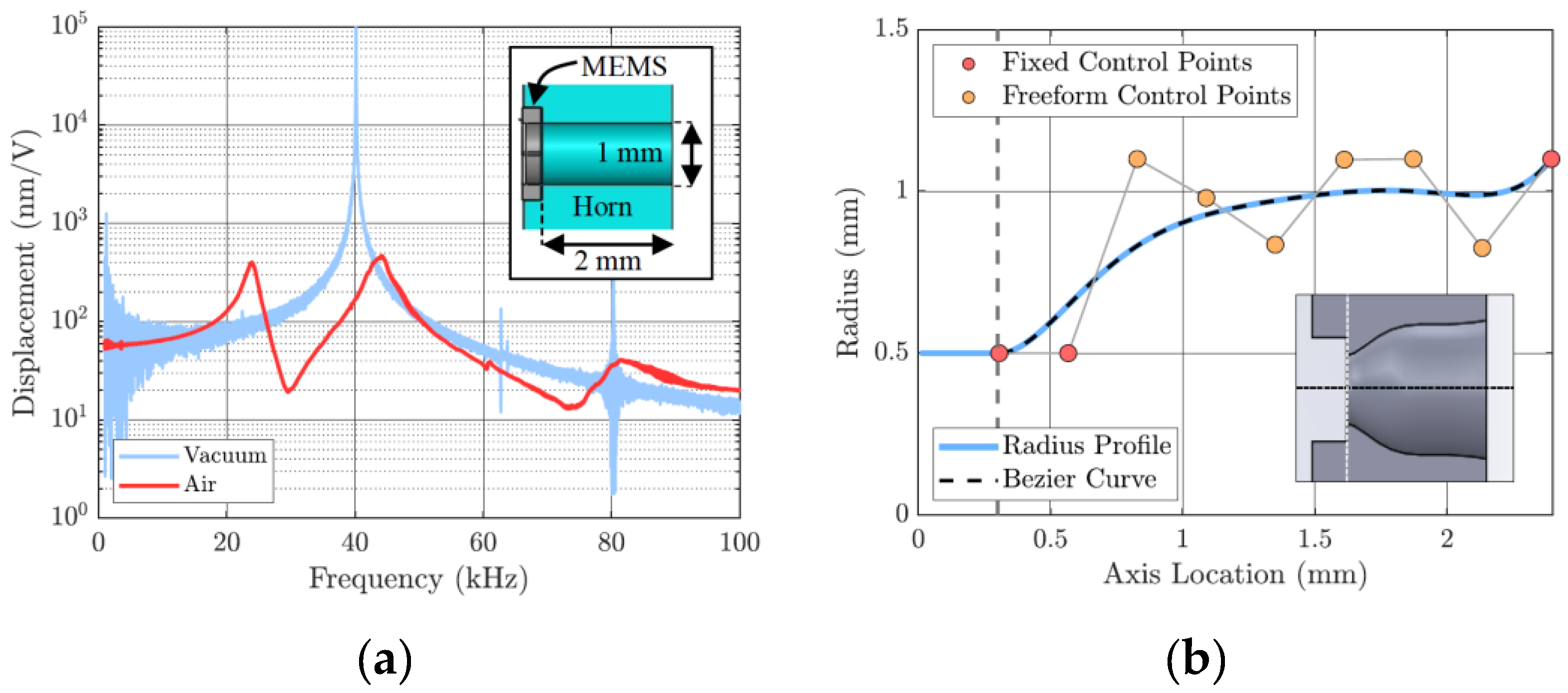
:1. Introduction
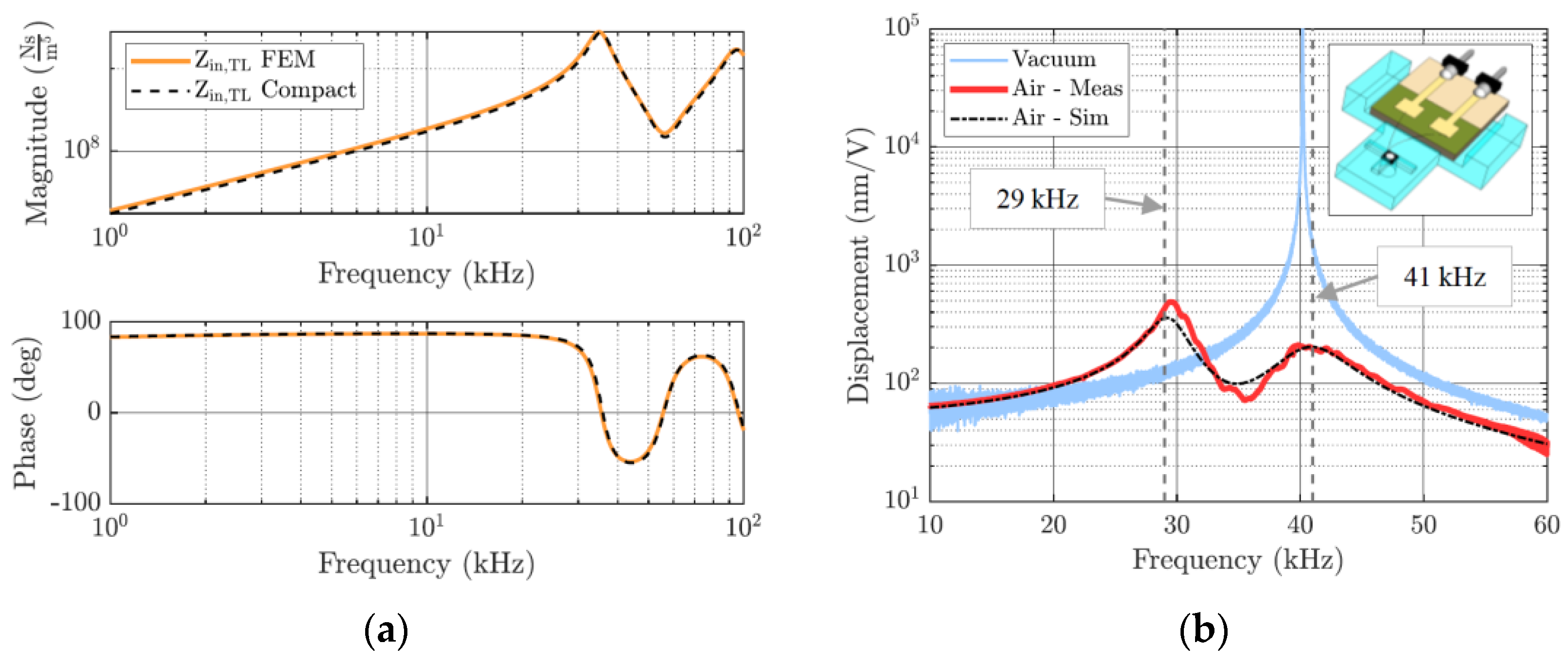
2. Methods
3. Discussion
Author Contributions
Funding
Institutional Review Board Statement
Informed Consent Statement
Data Availability Statement
Acknowledgments
Conflicts of Interest
References
- Bosetti, G.; Hofstetter-Spona, S.; Schrag, G. On the Use of 3D-Printed Ultrasonic Horns to Tune the Frequency Response of Airborne Mems Transducers. In Proceedings of the Transducers Conference, Kyoto, Japan, 25–29 June 2023. [Google Scholar]
- Bosetti, G.; Schrag, G. Efficient Modeling of Acoustic Channels—Towards Tailored Frequency Response of Airborne Ultrasonic MEMS Transducers. In Proceedings of the EuroSimE Conference, St. Julian, Malta, 25–27 April 2022. [Google Scholar]

Disclaimer/Publisher’s Note: The statements, opinions and data contained in all publications are solely those of the individual author(s) and contributor(s) and not of MDPI and/or the editor(s). MDPI and/or the editor(s) disclaim responsibility for any injury to people or property resulting from any ideas, methods, instructions or products referred to in the content. |
© 2024 by the authors. Licensee MDPI, Basel, Switzerland. This article is an open access article distributed under the terms and conditions of the Creative Commons Attribution (CC BY) license (https://creativecommons.org/licenses/by/4.0/).
Share and Cite
Bosetti, G.; Hofstetter-Spona, S.; Schrag, G. Freeform Optimization of an Ultrasonic Horn Coupled to an Airborne MEMS Transducer. Proceedings 2024, 97, 151. https://doi.org/10.3390/proceedings2024097151
Bosetti G, Hofstetter-Spona S, Schrag G. Freeform Optimization of an Ultrasonic Horn Coupled to an Airborne MEMS Transducer. Proceedings. 2024; 97(1):151. https://doi.org/10.3390/proceedings2024097151
Chicago/Turabian StyleBosetti, Gabriele, Stefan Hofstetter-Spona, and Gabriele Schrag. 2024. "Freeform Optimization of an Ultrasonic Horn Coupled to an Airborne MEMS Transducer" Proceedings 97, no. 1: 151. https://doi.org/10.3390/proceedings2024097151