
Flexural Plate Wave Piezoelectric MEMS Pressure Sensor †
by
 , , , , and
Alessandro Nastro
1,* ,
,
Stefano Bertelli
1,
Marco Ferrari
1,
Libor Rufer
2 ,
,
Skandar Basrour
3 and
Vittorio Ferrari
1 1
Department of Information Engineering, University of Brescia, 25123 Brescia, Italy
2
ADT MEMS, 38140 Grenoble, France
3
CNRS, Grenoble INP, TIMA, University Grenoble Alpes, 38000 Grenoble, France
*
Author to whom correspondence should be addressed.
†
Presented at the XXXV EUROSENSORS Conference, Lecce, Italy, 10–13 September 2023.
Proceedings 2024, 97(1), 185; https://doi.org/10.3390/proceedings2024097185
Published: 15 April 2024
Abstract
:A piezoelectric MEMS pressure sensor that exploits the first antisymmetric vibration mode (A0) of Lamb waves is presented. The 6 mm × 6 mm diaphragm used to sense the applied pressure is composed of a stack of doped silicon (Si) and aluminum nitride (AlN) layers with metal interdigital transducers (IDTs) to generate flexural plate waves (FPWs). The working principle has been validated through 2D finite element analysis within the frequency range 10–15 MHz and experimentally verified. A variable pressure has been applied across the diaphragm while measuring the electrical admittance of a single IDT. Experimental data are in good agreement with simulations showing a frequency shift of the admittance peaks when pressure acts on the MEMS diaphragm. For an applied pressure of 170 Pa, a relative frequency variation of 0.25% has been achieved.
Keywords:
flexural plate waves; Lamb waves; MEMS; piezoelectric; PiezoMUMPs; pressure sensor; FEM; electrical admittance1. Introduction
Lamb wave piezoelectric MEMS pressure sensors exploit the variation in the propagation of guided plate waves in a micromachined diaphragm due to the pressure exerted on it by a surrounding medium [1]. These sensors have the advantage to operate in the low-megahertz frequency range with high sensitivity and can function in contact with liquids at low losses [2]. In this context, a piezoelectric MEMS pressure sensor exploiting Lamb waves in a diaphragm at the first antisymmetric vibration mode is described, simulated, and experimentally verified.
2. Description and Validation of the MEMS Pressure Sensor
The proposed sensor has been fabricated by the PiezoMUMPs process [3] and embeds a 6 mm × 6 mm squared cavity etched out in a silicon substrate bounded by a composite diaphragm made of a stack of silicon and piezoelectric AlN layers. The composite diaphragm can be electrically actuated by means of metal interdigital transducers (IDTs), composed of two interleaved comb-shaped electrodes of N = 10 equally spaced fingers each with pitch p = 112 μm.
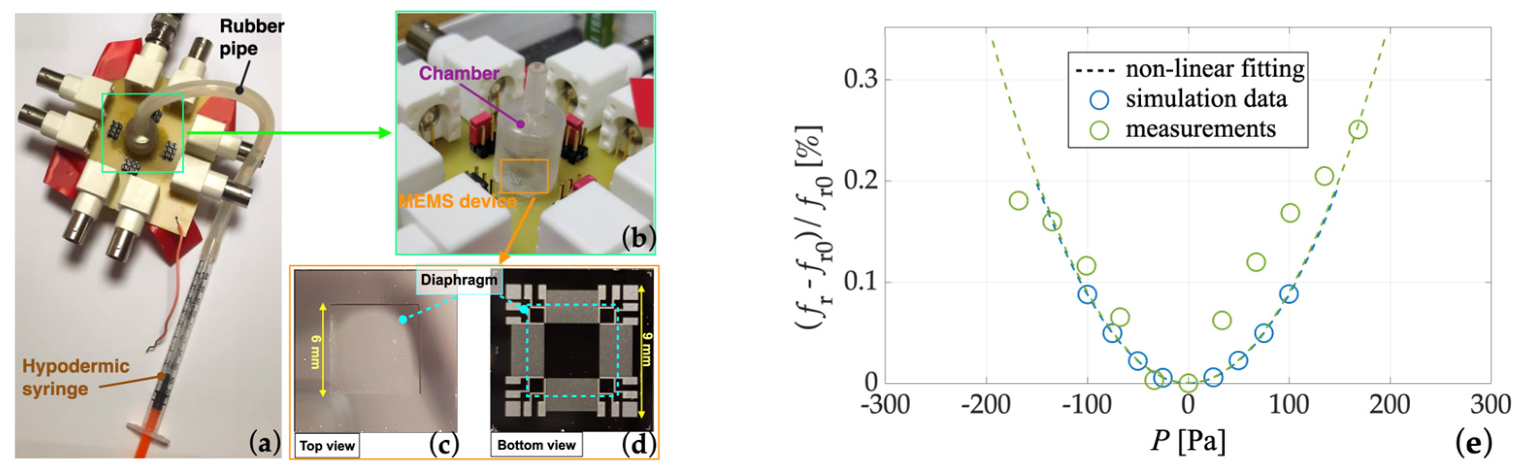
By applying sinusoidal excitation voltage v(t) between the fingers of the IDTs, a deformation of the piezoelectric layer is induced which produces mechanical vibrations in the diaphragm in the form of Lamb plate waves, as shown in Figure 1a. Specifically, the first antisymmetric mode (A0) has been excited which is located at the synchronous frequency fA0 = vA0/p where vA0 is the A0 mode phase velocity, resulting in fA0 at about 13 MHz. By applying a pressure P loading one of the diaphragm faces with the other face kept at ambient pressure, a tensile stress is induced, as visible in Figure 1b. This is expected to produce a frequency shift in the IDT admittance pattern centered at fA0 of the A0 mode [2]. The working principle has been investigated by means of 2D finite element modelling in COMSOL Multiphysics®. A frequency domain analysis has been performed to evaluate the electrical admittance Y(f) of a single IDT, as shown in Figure 2a, with a variable pressure applied. The excitation frequency f has been swept in the bandwidth between 10 and 15 MHz and the applied pressure P has been varied from −100 to 100 Pa spanning a bipolar range. Figure 2b reports the simulated conductance G(f) of IDT3 as a function of the excitation frequency f. As expected, the obtained series of peaks exhibits a rigid positive frequency shift as a function of P regardless of its sign, as shown in the inset of Figure 2b where a single peak of G(f) is visualized. The working principle has been experimentally validated by employing an impedance analyzer (HP4194A) and the setup shown in Figure 3a. Pressure has been applied by a syringe connected to a sealed chamber containing the MEMS sensor, as shown in Figure 3b–d. Figure 3e shows the obtained simulated and measured relative resonant frequency variation (fR − fR0)/fR0 as a function of P where fR0 is the resonant frequency at zero pressure applied. The frequency fR is the frequency where the conductance G(f) reaches the maximum peak. For P = 170 Pa a relative frequency variation of 0.25% has been measured. The obtained data are in good agreement with the simulations. The residual discrepancies can be ascribed to the fabrication process tolerances and the residual imperfections in the experimental setup.
Author Contributions
Methodology, A.N., S.B. (Stefano Bertelli) and M.F.; software, A.N.; validation, A.N. and S.B. (Stefano Bertelli), device design, V.F. and L.R.; investigation, A.N. and M.F.; writing—original draft preparation, A.N.; writing—review and editing, A.N., S.B. (Stefano Bertelli), M.F., L.R., S.B. (Skandar Basrour) and V.F.; conceptualization and supervision, V.F. All authors have read and agreed to the published version of the manuscript.
Funding
This research received no external funding.
Conflicts of Interest
The authors declare no conflict of interest.
References
- Kropelnicki, P.; Muckensturm, K.-M.; Mu, X.J.; Randles, A.B.; Cai, H.; Ang, W.C.; Tsai, J.M.; Vogt, H. CMOS- compatible ruggedized high-temperature Lamb wave pressure sensor. J. Micromech. Microeng. 2013, 23, 085018. [Google Scholar] [CrossRef]
- Wenzel, S.W.; White, R.M. A multisensor employing an ultrasonic Lamb-wave oscillator. IEEE Trans. Electron Devices 1988, 35, 735–743. [Google Scholar] [CrossRef]
- Nastro, A.; Ferrari, M.; Rufer, L.; Basrour, S.; Ferrari, V. Piezoelectric MEMS Acoustic Transducer with Electrically-Tunable Resonant Frequency. Micromachines 2022, 13, 96. [Google Scholar] [CrossRef]
Figure 1.
Cross-section views of the proposed piezoelectric MEMS pressure sensor without (a) and with (b) the pressure P applied.
Figure 1.
Cross-section views of the proposed piezoelectric MEMS pressure sensor without (a) and with (b) the pressure P applied.
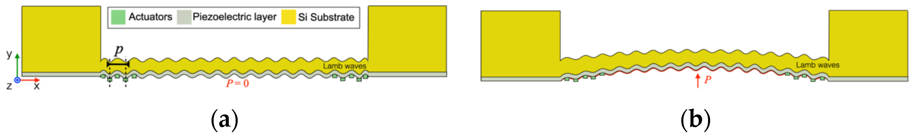
Figure 2.
Simplified schematic view of the proposed MEMS device configured for the simulation of the electrical admittance (a). Simulated conductance G(f) of a single IDT as a function of the excitation frequency f at different pressure P (b). Enlarged view of a single peak of G(f) (inset).
Figure 2.
Simplified schematic view of the proposed MEMS device configured for the simulation of the electrical admittance (a). Simulated conductance G(f) of a single IDT as a function of the excitation frequency f at different pressure P (b). Enlarged view of a single peak of G(f) (inset).
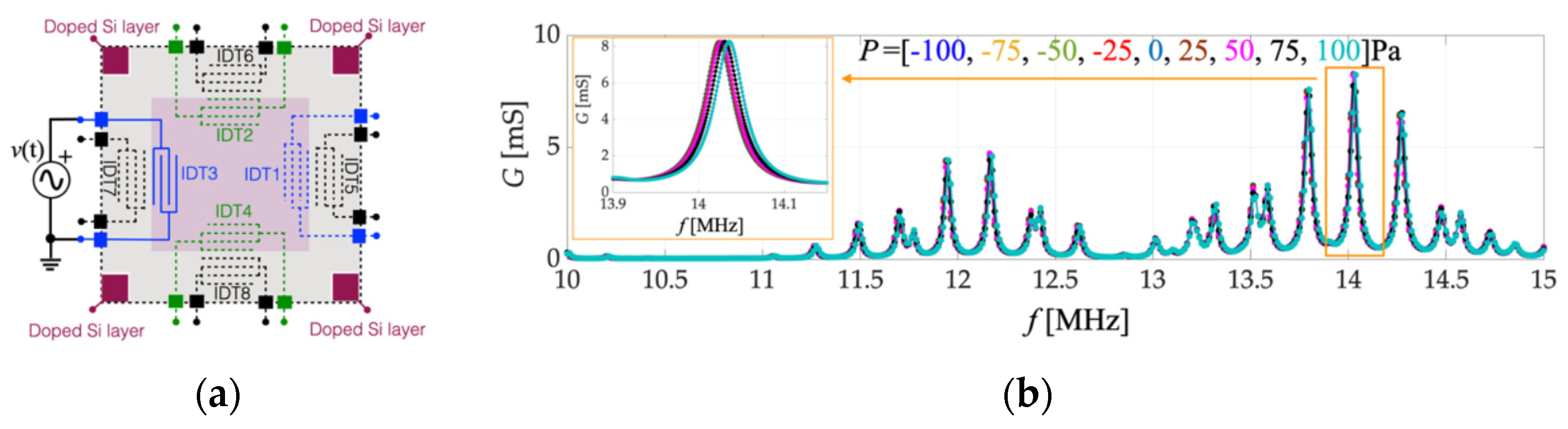
Figure 3.
Experimental setup employed to test the MEMS pressure sensor (a). Enlarged view of the sealed chamber (b). Top (c) and bottom (d) views of the fabricated MEMS device. Comparison (e) of the simulated (blue circles) and measured (green circles) relative resonant frequency variation and non-linear fittings (dotted curves) as a function of the applied pressure P.

Disclaimer/Publisher’s Note: The statements, opinions and data contained in all publications are solely those of the individual author(s) and contributor(s) and not of MDPI and/or the editor(s). MDPI and/or the editor(s) disclaim responsibility for any injury to people or property resulting from any ideas, methods, instructions or products referred to in the content. |
© 2024 by the authors. Licensee MDPI, Basel, Switzerland. This article is an open access article distributed under the terms and conditions of the Creative Commons Attribution (CC BY) license (https://creativecommons.org/licenses/by/4.0/).
Share and Cite
MDPI and ACS Style
Nastro, A.; Bertelli, S.; Ferrari, M.; Rufer, L.; Basrour, S.; Ferrari, V. Flexural Plate Wave Piezoelectric MEMS Pressure Sensor. Proceedings 2024, 97, 185. https://doi.org/10.3390/proceedings2024097185
AMA Style
Nastro A, Bertelli S, Ferrari M, Rufer L, Basrour S, Ferrari V. Flexural Plate Wave Piezoelectric MEMS Pressure Sensor. Proceedings. 2024; 97(1):185. https://doi.org/10.3390/proceedings2024097185
Chicago/Turabian StyleNastro, Alessandro, Stefano Bertelli, Marco Ferrari, Libor Rufer, Skandar Basrour, and Vittorio Ferrari. 2024. "Flexural Plate Wave Piezoelectric MEMS Pressure Sensor" Proceedings 97, no. 1: 185. https://doi.org/10.3390/proceedings2024097185