Article

Parallel Multiobjective Multiverse Optimizer for Path Planning of Unmanned Aerial Vehicles in a Dynamic Environment with Moving Obstacles

1
Research Laboratory in Automatic Control (LARA), National Engineering School of Tunis (ENIT), University of Tunis EL Manar, Le Belvédère, Tunis 1002, Tunisia
2
High Institute of Industrial Systems of Gabès (ISSIG), University of Gabès, Gabès 6011, Tunisia
3
Department of Electrical Engineering, College of Engineering in Wadi Alddawasir, Prince Sattam bin Abdulaziz University, Al-Kharj 11942, Saudi Arabia
4
Control and Instrumentation Engineering Department, King Fahd University of Petroleum & Minerals, Dhahran 31261, Saudi Arabia
5
Interdisciplinary Research Center (IRC) for Renewable Energy and Power Systems, King Fahd University of Petroleum & Minerals, Dhahran 31261, Saudi Arabia
*
Author to whom correspondence should be addressed.
Drones 2022, 6(12), 385; https://doi.org/10.3390/drones6120385
Submission received: 16 October 2022 / Revised: 15 November 2022 / Accepted: 25 November 2022 / Published: 28 November 2022
(This article belongs to the Special Issue Drones in the Wild)

Abstract

:
Path planning with collision avoidance for unmanned aerial vehicles (UAVs) in environments with moving obstacles is a complex process of navigation, often considered a hard optimization problem. Ordinary resolution algorithms may fail to provide flyable and collision-free paths under the time-consumption constraints required by the dynamic 3D environment. In this paper, a new parallel multiobjective multiverse optimizer (PMOMVO) is proposed and successfully applied to deal with the increased computation time of the UAV path planning problem in dynamic 3D environments. Collision constraints with moving obstacles and narrow pass zones were established based on a mathematical characterization of any intersection with lines connecting two consecutive drones’ positions. For the implementation, a multicore central processing unit (CPU) architecture was proposed according to the concept of master–slave processing parallelization. Each subswarm of the entire PMOMVO population was granted to a corresponding slave, and representative solutions were selected and shared with the master core. Slaves sent their local Pareto fronts to the CPU core representing the master that merged the received set of nondominated solutions and built a global Pareto front. Demonstrative results and nonparametric ANOVA statistical analyses were carried out to show the effectiveness and superiority of the proposed PMOMVO algorithm compared to other homologous, multiobjective metaheuristics.

1. Introduction

Nowadays, unmanned aerial vehicles (UAVs) have gained great potential in several applications involving military and civilian fields due to their advantages in terms of weight, size, mobility, and price [1,2]. In robotics, path planning is the part of navigation that deals with collision avoidance of unmanned vehicles [3,4]. It is the most important issue in a vehicle’s navigation that aims to find the shortest and collision-free path from the current robot’s location to a given target. In many real-world navigation missions, a UAV’s flight environment can be dynamic with obstacles and threats that change over time. In these hard conditions, the collision-free path planning task becomes more and more difficult and expensive, leading to a great challenge in the UAV’s control and autonomous navigation framework [5,6,7,8]. In dynamic environments, a UAV drone operates regarding the location and motion speed of the moving obstacles. The drone must respect these dynamic constraints and react quickly to these types of changes. Therefore, planning algorithms used in this formalism must present high performance mainly in terms of execution time and processing speediness.
In the literature, several research works on UAV path planning problems have been proposed and continue to be developed and extended. In this framework, the aim of the path planning techniques is not only to find the shortest flyable path but also to ensure collision-free flight capability in complex environments. From this observation, the collision avoidance issue remains the main objective in any path planning task. Various methods and techniques have been investigated for collision avoidance in aviation. In [9], a dynamic collision avoidance zone modeling approach was proposed based on the emergency collision avoidance trajectory of UAVs in a 3D environment. In such a collision avoidance strategy, a virtual cylinder static protection zone was constructed for flight conflict detection and near-midair collision with intruders. In [10], the authors investigated the problem of cognitive UAV collision avoidance based on impulse differential inclusions theory. Simulation results were carried out to verify the stability of the computed collision avoidance region. In [11], a new collision and detection avoidance (CDA) algorithm was proposed to solve conflicts in flight scenarios with the simultaneous presence of aircrafts and other path constraints, such as no-fly zones, bad weather areas, hard terrain with geofencing limitations, and so on. The elaborated CDA approach leads to the detection of hazardous situations and the generation of optimal maneuvers that avoid potential collisions without causing secondary conflicts. Real-time simulations were made to show the effectiveness of the collision avoidance algorithm in challenging conflict scenarios. In [12], a modified artificial potential field (MAPF) approach was addressed for UAV collision avoidance in a dynamic 3D space. To increase the reliability of collision avoidance, a cylindrical region was assigned to each obstacle as an uncertain zone, and the planned path was checked with updated forces of MAPF while being executed by the UAV. The MAPF algorithm was designed and tested experimentally in a constraint reference frame to decouple the decomposed forces with specific physical constraints. A corrected path was then created if the forces disagreed with the physical constraints. In [13], a real-time collision avoidance strategy based on an essential visibility graph (EVG) algorithm was developed and applied for multiple unmanned aircrafts in environments with obstacles and no-fly zones. By updating the proposed EVG over the prediction time interval, a replanning procedure was carried out regarding the available multiple flying vehicles and movable obstacles. Another popular class of path planning with collision avoidance methods based on rapidly exploring random tree (RRT) techniques has been extensively used. In [14], an extended RRT algorithm was deployed for fixed-wing UAVs flying in a complex 3D environment with the avoidance of multiple obstacles. In [15], a dynamic variant of the RRT algorithm was applied to fixed-wing UAVs in a dynamic 3D environment. The RRT structure was expanded by considering the constraint equations of the vehicle’s dynamic constraints. The collision avoidance was guaranteed by considering the locations of the dynamic obstacles at the time of each step and interpolation based on the B-spline method. In [16], an improved RRT-based cooperative path planning algorithm was designed to deal with the real-time collision avoidance problem of multiple UAVs in the presence of unknown popup obstacles and teammate vehicles.
Taken as a hard optimization problem with contradictory objectives and constraints, the path planning problem with collision avoidance challenges requires many other capabilities of resolution algorithms in terms of search diversity, escape of local minima, nonpremature convergence, and computation time fastness to deal with the complexity of dynamic navigation environments. In recent years, interesting metaheuristics approaches have been proposed to solve a wide range of multicriteria path planning problems for UAVs in static and dynamic environments [17]. In [18], an algorithm based on both ant colony optimization and artificial potential field technique was proposed to solve UAV path planning problems in an environment with dynamic threats. The authors in [19] used an improved pigeon-inspired optimization algorithm for UAV path planning in a dynamic oilfield 3D environment. In [20], a novel optimization-based planner inspired by the concept of predator-prey pigeons was investigated to find the optimal trajectory for an unmanned combat aerial vehicle in a dynamic environment. In [21], an improved artificial bee colony algorithm was proposed for path planning problems in a complex dynamic environment. Although these works were developed to solve multiobjective path planning problems, they used weighted sum functions that converted the multiobjective problem into a single objective one [22]. In this case, it is difficult to determine the best weights for different conflicting goals. In order to overcome these limitations, multiobjective metaheuristics have been proposed to address multiple conflicting objectives simultaneously. In [23], a multiobjective particle swarm optimizer was applied for path planning in an uncertain environment. In [24,25,26], the authors proposed an interesting UAV collision-free path planning approach based on the multiverse multiobjective optimization concept. The comparisons carried out with other homologous algorithms have shown the effectiveness and superiority of the proposed planner in 3D environments with moving obstacles and threats. Other bioinspired metaheuristics algorithms have been used to handle the path planning problems of UAVs in dynamic environments and can be found in [27,28,29,30,31].
In a dynamic environment, the locations of moving obstacles change over time and the drone should be able to react quickly to these environmental changes. Therefore, the execution time of any path planning algorithm plays an important role in ensuring the feasibility of a real-world UAV’s navigation mission. Thus, there is a need to improve the classical optimization-based path planning methods by either modifying the search mechanism of algorithms or using advanced computational technologies to better solve these hard and large-scale planning problems. Recently, the parallelization of algorithms has been extensively developed and presents a promising and encouraging solution in this regard [32]. Architectures using graphics processing units (GPUs) and central processing units (CPUs) are the most extensively proposed parallelization techniques. With the growing development of computer technology, microprocessors currently used in almost all embedded computers have become multicore, providing the essential hardware bases for the implementation of parallel algorithms [33]. Nowadays, the computing technology of multicore CPU has enjoyed great success in the fields of scientific research and engineering practices and has become an active research area. Parallel computing in multicore CPUs is done by dividing a large computational task into several reduced subtasks that are executed simultaneously in the different cores. This parallelization technique can speed up computation time and further improve the efficiency of using hardware resources [34]. In our previous work [32], a parallel cooperative co-evolutionary grey wolf optimizer was proposed to solve the path planning problem using a multicore CPU architecture but in a static environment with single objective optimization formulation. Other works dealing with the parallelization of some classical and old metaheuristics algorithms can be found in the literature.
So far, no remarkable research work on the parallelization of recent and multiobjective metaheuristics algorithms for the dynamic path planning problems of UAVs is worth mentioning. In this paper, a new parallel multiobjective multiverse optimization (PMOMVO) algorithm is proposed and successfully applied to solve the path planning problem of UAVs flying in hard 3D environments with moving obstacles and threats. By using a multicore CPU architecture, a master–slave parallelization was implemented to lead to efficient and more suitable PMOMVO algorithms for the considered path planning problem compared with the normal MOMVO one. A modified technique for order of preference by similarity to ideal solution (TOPSIS) was used to select the best compromise solutions among all the nondominated ones in the sense of Pareto [35]. The research mechanism behind the MOMVO’s parallelization is explained and tested over a large benchmark of hard planning scenarios. To assess the usefulness of the proposed planning approach, several comparisons and statistical analyses were carried out and discussed. The main contributions of this work are summarized as follows: (1) an efficient path planning strategy is proposed to find flyable and collision-free paths in dynamic environments with moving obstacles and narrow pass zones. (2) A new parallel variant of the multiobjective multiverse optimizer based on a multicore CPU master–slave architecture is proposed and successfully applied for such a multicriteria path planning problem. (3) Nonparametric statistical analyses were carried out to show the efficiency and superiority of the proposed PMOMVO algorithm for path planning problems with moving obstacles.
The remainder of this paper is organized as follows. In Section 2, a bibliographic survey of the main methods and works on UAV path planning and collision avoidance in dynamic environments is summarized. In Section 3, the UAV path planning problem in a dynamic 3D environment with moving obstacles is formulated as a multiobjective optimization problem under operational dynamic constraints. Section 4 presents the main components of the proposed parallel processing multiobjective multiverse algorithm based on a master–slave multicore CPU architecture. In Section 5, demonstrative results, comparisons, and nonparametric statistical analyses are carried out to show the superiority and effectiveness of the proposed PMOMVO-based dynamic path planning approach. Section 6 concludes this paper.

2. Related Work

The path planning problem with collision avoidance in dynamic environments has attracted growing attention since the end of the last century. As a hard issue in UAV navigation, the main idea is to find flyable paths that can drive a vehicle safely from a start station to a target destination without colliding with moving obstacles. In the literature, many approaches using various kinds of algorithms have been proposed to tackle such a problem. Because of this broad range, many researchers have proposed different classification models to more easily identify trends and research directions. In this study, a chronological classification of the main and recent path planning methods is addressed in a horizon that ends in 2022. As summarized in Table 1, these approaches are grouped under five main classes, namely the sampling-, node-, mathematical-, machine-learning- and bioinspired metaheuristics-based algorithms. As shown from the related literature, the sampling-based algorithms are built around a required prerequisite of the knowledge of the working environment. In this case, collision-free environment information can be sampled and interpreted by a planning algorithm. The node-based techniques are used for finding flyable routes in a graph structure. In these algorithms, the predefined nature of the graph influences the applicability for unknown dynamic scenarios. For the mathematical-model-based approaches, the main idea consists of the resolution of the path planning task by a reformulation as a typical mixed-integer linear programming problem. Machine learning, i.e., reinforcement and deep learning, and bioinspired metaheuristics-based, techniques are the most extensively used approaches in recent decades. These approaches based on artificial intelligence concepts mimic the cognitive behaviors of neural networks, swarm intelligence, and biology.

3. Path Planning Problem Formulation

3.1. Dynamic Environment Modeling

In robotics, the path planning procedure consists of guiding the unmanned vehicle from a starting point S : x 1 , y 1 , z 1 to a destination point T : x n , y n , z n in the coordinate system XOY, as shown in Figure 1. The X-axis range that connects these two points is divided into n 1 equal subsegments denoted as L i , L i + 1 , i = 1 , 2 , , n 1 . To carry out this navigation mission, two key tasks must be determined, namely the 3D environment modeling (waypoints, obstacles, flyable paths, etc.) and the planning problem often formulated as a constrained multiobjective optimization problem [24,25,26,32].
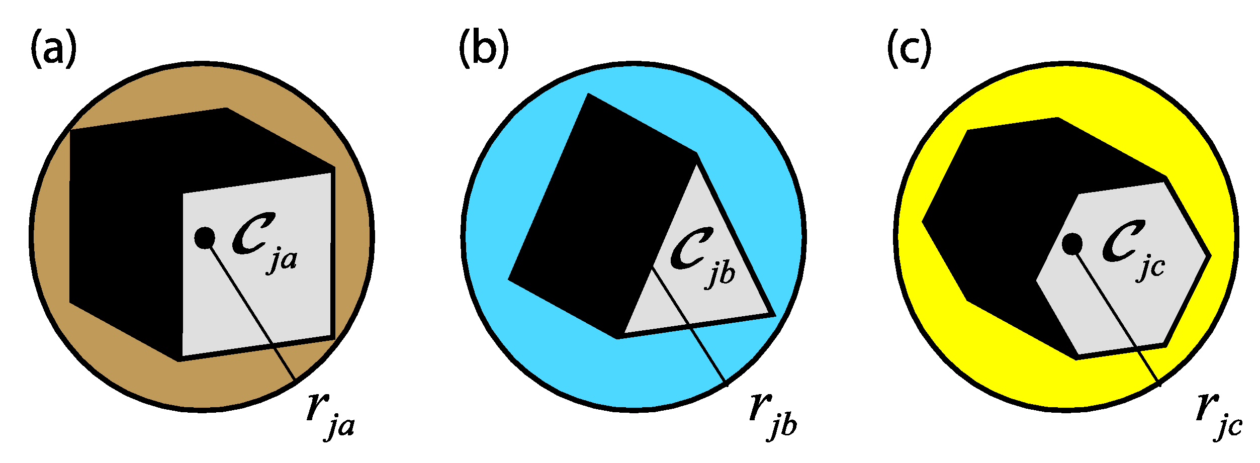
In this work and without loss of generality, a moving obstacle is modeled as a sphere or ball of radius r j + and center C j : x c j , y c j , z c j , as shown in Figure 2. Indeed, the idea behind the use of spherical shapes of threats aims to provide a more generalized collision-free navigation for a wide range of threat forms, for example, missiles, teammate drones in the case of multi-UAV swarms, raptors attacking the flying objects, and so on. In geometry, cubes, pyramids, and even more generally polygonal forms can be approximated as spheres (or as circles in 2D environments) circumscribed to various shapes of rigid objects. They are circumscribed spheres containing the polygonal object where all its vertices are still inside of the ball. The dynamic constraints of traversing areas in spherical shapes remain virtually the same. Moreover, several literature works on the 3D path planning of UAVs continue to use spherical shapes for a wide range of 3D obstacles and threats as well as circular forms in the case of planning in 2D environments. Thus, whatever the shape of the object that is considered an obstacle, the collision avoidance constraints manipulate analytical and nonlinear constraints analogous to those later developed in this same section.
On the other hand, a UAV drone as a rigid body moving in a 3D space is modeled thanks to the well-known Newton–Euler approach that describes the motion dynamics in the body-fixed coordinate frame as follows [26,31,32]:
m u a v X ¨ u a v = m u a v V ˙ u a v = F u a v
where X u a v = x u a v , y u a v , z u a v and V u a v = v u a v , u u a v , w u a v denote the position and linear velocity of the drone for the translational motion, respectively, m u a v is the mass of the vehicle, and F u a v is the sum of external forces. These motion equations are sampled according to the adequate time step Δ t .

3.2. Multiobjective Optimization Problem Formulation

Considering that the actual position of the aerial vehicle is w i = x i , y i , z i and the time t 0 is incremented by one unit, the drone must move to the next position w i + 1 = x i + 1 , y i + 1 , z i + 1 where the coordinate x i + 1 1 i n 1 is selected and the waypoint coordinates W = y i + 1 , z i + 1 1 i n 1 are considered as the decision variables for the path-planning-based optimization problem. The aim of the path planning problem in a dynamic 3D environment is to calculate the vehicle’s next positions while meeting certain objectives and avoiding collision with moving obstacles. Starting from its current position and heading towards its destination, the UAV drone is placed at the time t 0 in the spatial coordinate w i = x i , y i , z i . As the processing time is incremented Δ t , the quadrotor would pass to the next position w i + 1 = x i + 1 , y i + 1 , z i + 1 at the time t + Δ t . The length of the flyable, collision-free path is therefore an essential objective. The minimization of the lines joining the consecutive waypoints { x i , y i , z i , x i + 1 , y i + 1 , z i + 1 } and { x i + 1 , y i + 1 , z i + 1 , x n , y n , z n } leads to minimizing the total length of flyable paths. Thus, the first proposed objective function is defined as follows [24]:
f 1 W = x i + 1 x i 2 + y i + 1 y i 2 + z i + 1 z i 2 + x i + 1 x n 2 + y i + 1 y n 2 + z i + 1 z n 2
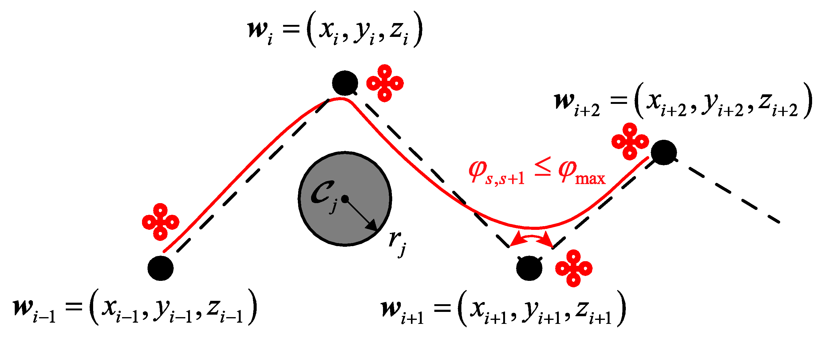
The consideration of the dynamic characteristics of UAVs is another essential objective [24,31,32]. The straighter the UAV drone’s flyable path, the more the control system complexity and fuel cost of the flight process decrease. However, in a real-world situation, a UAV should arbitrarily change its direction around waypoints and moving obstacles. Therefore, the candidate flyable path will present curvatures at any direction change and sharp corners. To handle such dynamic constraints of UAVs, the idea to use the concepts of steering angle and the corresponding turning radius was considered [31,32]. Such turning angles define the angles between two adjacent segments along the generated sequence of flyable waypoints, as depicted in Figure 3. The steering angle is then introduced to limit the straightness of the path and constrain the motion of the vehicle. Considering this dynamic behavior around waypoints, a second objective function that models such planning dynamic constraints can be chosen as follows [32]:
f 2 W = φ s , s + 1 φ max
where φ s , s + 1 = w i 1 w i , w i w i + 1 is the angle between two adjacent sth and (s+1)th segments connecting three consecutive waypoints, and φ max denotes the constraint value of this steering angle, as shown in Figure 3.
In dynamic environments, avoiding collision with moving obstacles is more complex and harder than in the case of static ones. Indeed, the drone must be able to coordinate its movement by avoiding any possible collision with a set of obstacles evolving in the navigation environment with position and speed variables in time [24]. In a real-world navigation environment, the geometric coordinates of dynamic obstacles are difficult to define. The main characteristics of obstacles, such as the center, the radius, the initial position, and the motion speed, are assumed to be known at the start of the planning process. At each time step, the position and speed motion equations of the jth given dynamic obstacle are updated as follows:
v o b s j t + Δ t = v o b s j t + a o b s j Δ t
x o b s j t + Δ t = x o b s j t + v o b s j t + Δ t Δ t + 1 2 a o b s j Δ t 2
y o b s j t + Δ t = y o b s j t + v o b s j t + Δ t Δ t + 1 2 a o b s j Δ t 2
z o b s j t + Δ t = z o b s j t + v o b s j t + Δ t Δ t + 1 2 a o b s j Δ t 2
where v o b s j and a o b s j are the motion speed and acceleration of the jth moving obstacle, respectively, j = 1 , 2 , , q , q , and Δ t 0 denotes the incremental time step size.
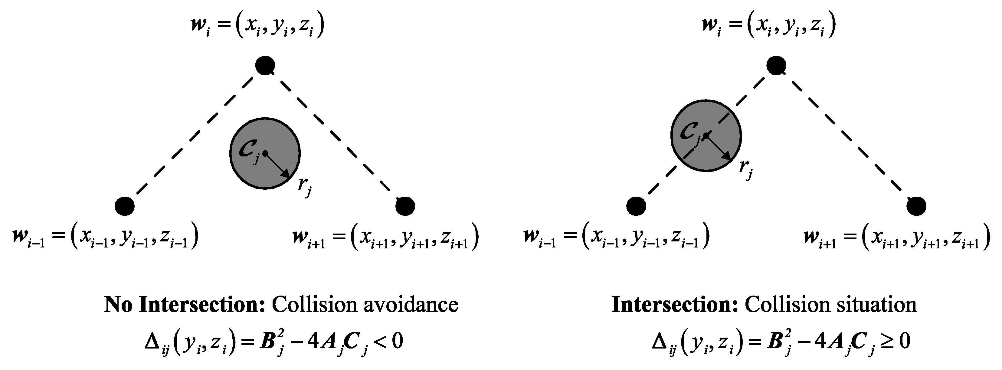
In such modeling, the UAV drone moves from the actual position w i = x i , y i , z i to the next one w i + 1 = x i + 1 , y i + 1 , z i + 1 when the time is incremented by one unit. To avoid any collision, the line connecting these two waypoints should not be crossed by a moving obstacle, as shown in Figure 4. Starting from a current instantaneous position and assuming that the UAV drone should not perform backward movements, the coordinates of the next consecutive waypoint can be expressed as follows:
x i + 1 = x i + t Δ x y i + 1 = y i + t Δ y z i + 1 = z i + t Δ z
where Δ x = x i + 1 x i , Δ y = y i + 1 y i , and Δ z = z i + 1 z i denote the increments on the drone’s positions according to X-, Y-, and Z-axes, respectively.
Any waypoint on the surface of the sphere has the coordinates x i , y i , z i that verify the following characteristic equation:
x i x c j 2 + y i y c j 2 + z i z c j 2 = r j 2
where x c j , y c j , z c j and r j represent the center’s coordinates and radius of the jth sphere-based modeled obstacle, respectively.
By substituting Equation (8) in Equation (9), one can obtain the following second-order polynomial equation:
A j t 2 + B j t + C j = 0
where the terms A j , B j , and C j are defined as follows:
A j = Δ x 2 + Δ y 2 + Δ z 2
B j = 2 Δ x x i 1 x c j + Δ y y i 1 y c j + Δ z z i 1 z c j
C j = x i 1 x c j 2 + y i 1 y c j 2 + z i 1 z c j 2 r j 2
When the discriminant of such a second-order equation is negative, there are no intersections between the line connecting two consecutive drones’ positions and the moving obstacle modeled as a sphere. Such an operational constraint is defined as follows:
Δ i j y i , z i = B j 2 4 A j C j
where j = 1 , 2 , , q is the index of the jth moving obstacle, i = 1 , 2 , , n 1 is the number of waypoints, and A j , B j , and C j are analytical terms given by Equations (11)–(13), respectively.
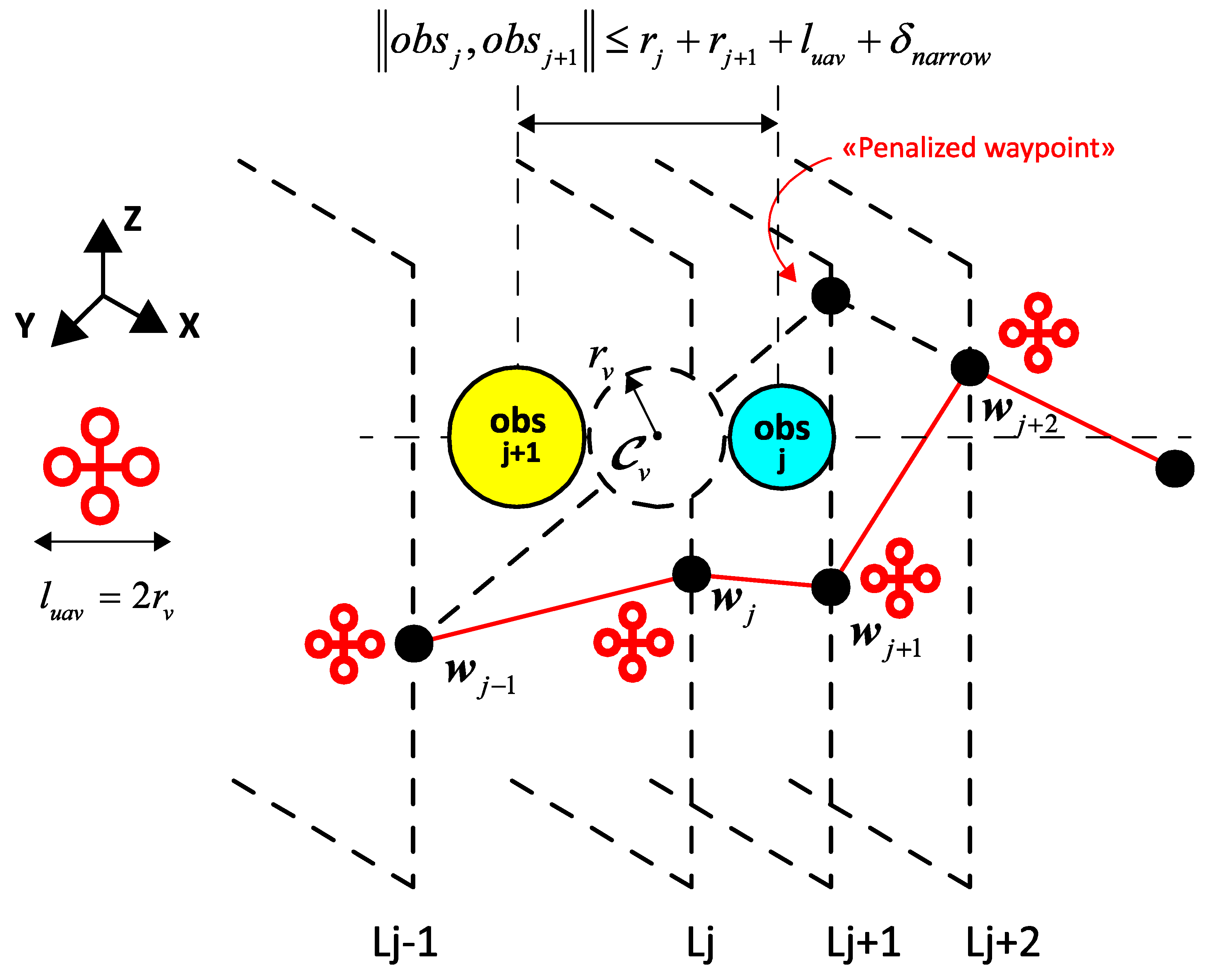
In addition, another type of collision situation can occur in the case of narrow passage between two moving obstacles located at the same altitude. In this case, i.e., generation of no feasible waypoint between two obstacles’ positions, the distance separating such two circumscribed spheres is insufficient to make a safe flight of the drone regarding its geometric dimensions. In such particular planning scenarios, a virtual sphere of radius r v = l u a v / 2 + and C v : x c v , y c v , z c v centered midway between two nearby obstacles is considered, as shown in Figure 5, where l u a v denotes the vehicle’s length and δ n a r r o w is a predefined safety distance of a narrow pass.
So, novel collision-free constraints of the same type as (14) can be defined by considering the intersection avoidance of the planned path segments with such virtual spheres, i.e., circumscribed to the narrow zone between obstacles. The waypoint assumed was generated when the drone passing between two nearby obstacles should be panelized. The UAV thus changes direction along the Z-axis, i.e., can fly above these obstacles or below them while respecting the safe distance from a possible collision with the ground. Another tolerated, feasible move consists of targeting the new waypoint of the next hyperplane, i.e., changing the direction along the Y-axis with a constant altitude, as depicted in Figure 5. From the optimization point of view, such a constraint for path planning regarding narrow passes between moving obstacles can be modeled as follows:
Δ v i j y i , z i = B v 2 4 A v C v
where the terms A v , B v , and C v can be computed using the same Formulas (11)–(13) but by replacing the radius r j with r v and the center coordinates x c j , y c j , z c j with those of the defined virtual sphere x c v , y c v , z c v .
Based on these modeling specifications and for the generation of the ith waypoint, the UAV’s path planning process in a dynamic environment with moving obstacles can be formulated as the following constrained multiobjective optimization problem:
Minimize W D 2 φ W = f 1 W , f 2 W s . t : g i j W < 0 h i j W < 0
where f 1 . and f 2 . are the cost functions of the biobjective optimization problem given by Equations (2) and (3), g i j . = Δ j . and h i j . = Δ v i j . are the collision-free constraints of the moving obstacles defined by Equations (14) and (15), W = y i , z i 1 i n 1 are the decision variables of the problem, and D = W 2 | W min W W max , g i j W < 0 , h i j W < 0 , i = 1 , 2 , , n ; j = 1 , 2 , , q denotes the bounded search space.
To handle the inequality constraints of the formulated multiobjective optimization problem (16), the external, static type of penalty functions are used as follows [47]:
ϕ k W = f k W + i = 1 n j = 1 p λ i j max 0 , g i j W + h i j W 2
where λ i j + is the jth penalty parameter associated with the jth constraint, p q is the number of obstacles in the ith waypoint’s neighborhood that denotes the number of considered inequality constraints in the optimization, and k 1 , 2 .

3.3. Proposed Path Planning Strategy

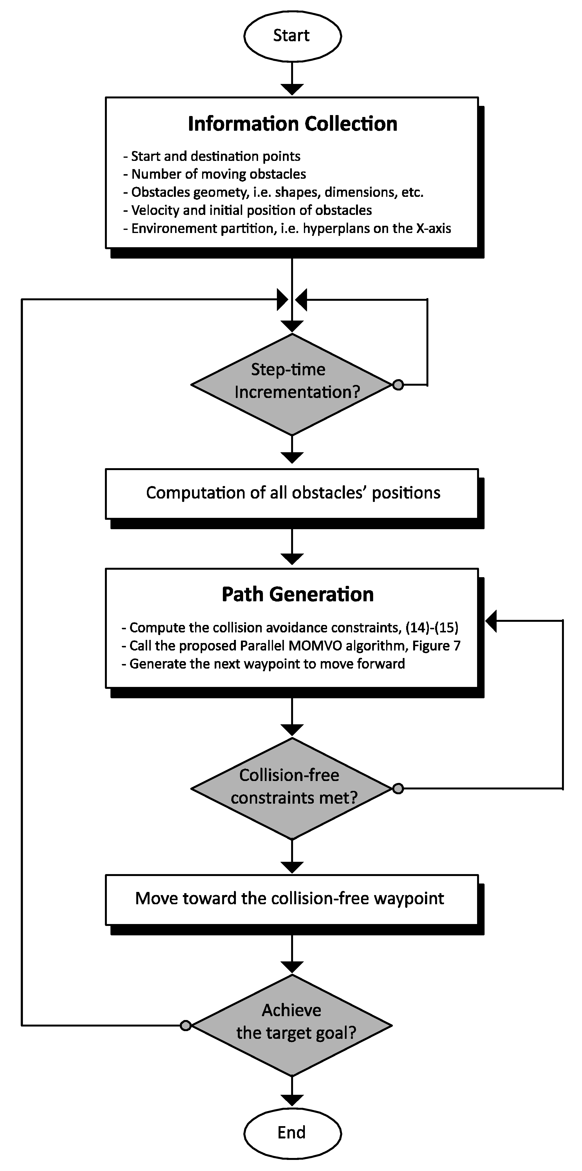
Obstacle collision avoidance is fundamental within any dynamic path planning problem with UAVs. Based on the assumptions that the number, initial positions, and range of velocity of the moving obstacles are known, the proposed UAV path planning strategy consists of determining appropriate collision-free waypoint sequences in 3D environments with moving threats. Allowing for safe navigation from a starting point to a destination station, the designed path planning technique is based on the first step of the collection of the environment’s information, i.e., start and target points, number and dimension of moving obstacles, initial positions of obstacles, etc. As shown in the flowchart of Figure 6, the modeling of the 3D flight environment regarding the workspace partition, UAV dynamic constraints, and the geometry of moving obstacles should be investigated. At each increment of the computation time, the generation of collision-free waypoints is then performed using the proposed parallel processing PMOMVO planner (see the corresponding Algorithm 2 and the flowchart of Figure 6). Such an improved PMOMVO algorithm, associated with a TOPSIS type of multicriteria decision-making approach, aims to increase the performance of the dynamic planner in terms of computation time and trapping avoidance in local minima. A geometric technique to formulate moving obstacle avoidance is proposed based on the intersection of the segments connecting the generated waypoints with any obstacle assumed to be circumscribed in a 3D sphere with known centers and radii, as illustrated in Figure 4 and Figure 5. The generated collision-free waypoints are then targeted by the UAV drone while respecting the defined dynamic constraints, i.e., steering angles, straightness limitation, and narrow passage constraints, as shown in Figure 3, Figure 4 and Figure 5.

4. Parallel Optimization Algorithm

4.1. Multiobjective Multiverse Optimizer

The standard Multiverse Optimizer (MVO) is a population-based metaheuristic inspired by physical theories of the existence of the multiverse [48]. This swarm-intelligence-based algorithm models the interaction between different universes based on the notion of black/white holes and wormholes [48,49]. The sending and receiving of objects in a universe (decision variables) through wormholes are done according to their inflation rates (fitness values) to improve the process of exploration/exploitation and to avoid entrapment in local optima. The main motion equations of such an algorithm are defined as follows:
W i j = W j + T D R + u b j l b j × r a n d 3 + l b j r a n d 2 < 0.5 W j + T D R u b j l b j × r a n d 3 + l b j r a n d 2 < 0.5 if   r a n d 1 < W E P W i j if   r a n d 1 W E P
where W i j denotes the jth component in the ith solution, W j indicates the jth variable of the best universe, l b j and u b j are the lower and upper bounds, respectively, r a n d 1 , 2 , 3 U 0 , 1 are random numbers uniformly distributed in the interval [0, 1].
In Equation (18), the terms W E P and T D R that present the wormhole existence probability and traveling distance rate, respectively, are defined as follows:
W E P = ρ min + i t e r ρ max ρ min / n i t e r
T D R = 1 i t e r 1 / γ / n i t e r
where ρ min and ρ max are the min and max values of the wormhole existence probability, respectively, i t e r = 1 , 2 , , n i t e r denotes the current algorithm’s iteration, and γ + defines the exploitation accuracy.
In this paper, a multiobjective variant of the multiverse optimizer (MOMVO) is developed by adding the concepts of archiving to store the nondominant solutions in the sense of Pareto. The leader selection and roulette techniques are implemented to select the best solutions from the Pareto archive. Since an archive can accommodate a limited number of nondominant solutions, a probabilistic mechanism is used to remove unsatisfactory solutions [49]:
δ i = N i / α
where N i defines the number of the vicinity solutions and α > 1 is a constant.
Based on the above updating equations, a pseudocode of the proposed MOMVO can be summarized as follows (Algorithm 1):
Algorithm 1: MOMVO
1.
Set the control parameters of MOMVO.
2.
Randomly initialize the population, i.e., positions of the universes.
3.
While ( i t e r < n i t e r + 1 ) do
4.
Update W E P and T D R by applying Equations (19) and (20), “See Section 4.1”.
5.
For each universe do
Boundary checking for the universes inside the search space.
Calculate the inflation rate (fitness) of universes.
End For
6.
Sort the fitness values.
7.
Find the nondominated solutions.
8.
Normalize the inflation rates of each universe.
9.
Update the archive regarding the obtained nondominated solutions.
10.
If the archive is full do
Delete some solutions from the archive to hold the new.
End if
11.
Update the positions of universes according to Equation (18), “See Section 4.1”.
12.
If any newly added solutions to the archive are outside boundaries do
Update the boundaries to cover the new solution(s).
End if
13.
Increment i t e r
14.
Stop the algorithm’s execution when it reaches n i t e r .
On the other hand, a decision-making approach is required to select the best compromise solution among all the nondominated Pareto ones. For the formulated multicriteria path planning problem (16), an improved technique for order of preference by similarity to ideal solution (TOPSIS) is adopted as in our previous works [35].

4.2. Parallelization of the MOMVO Algorithm

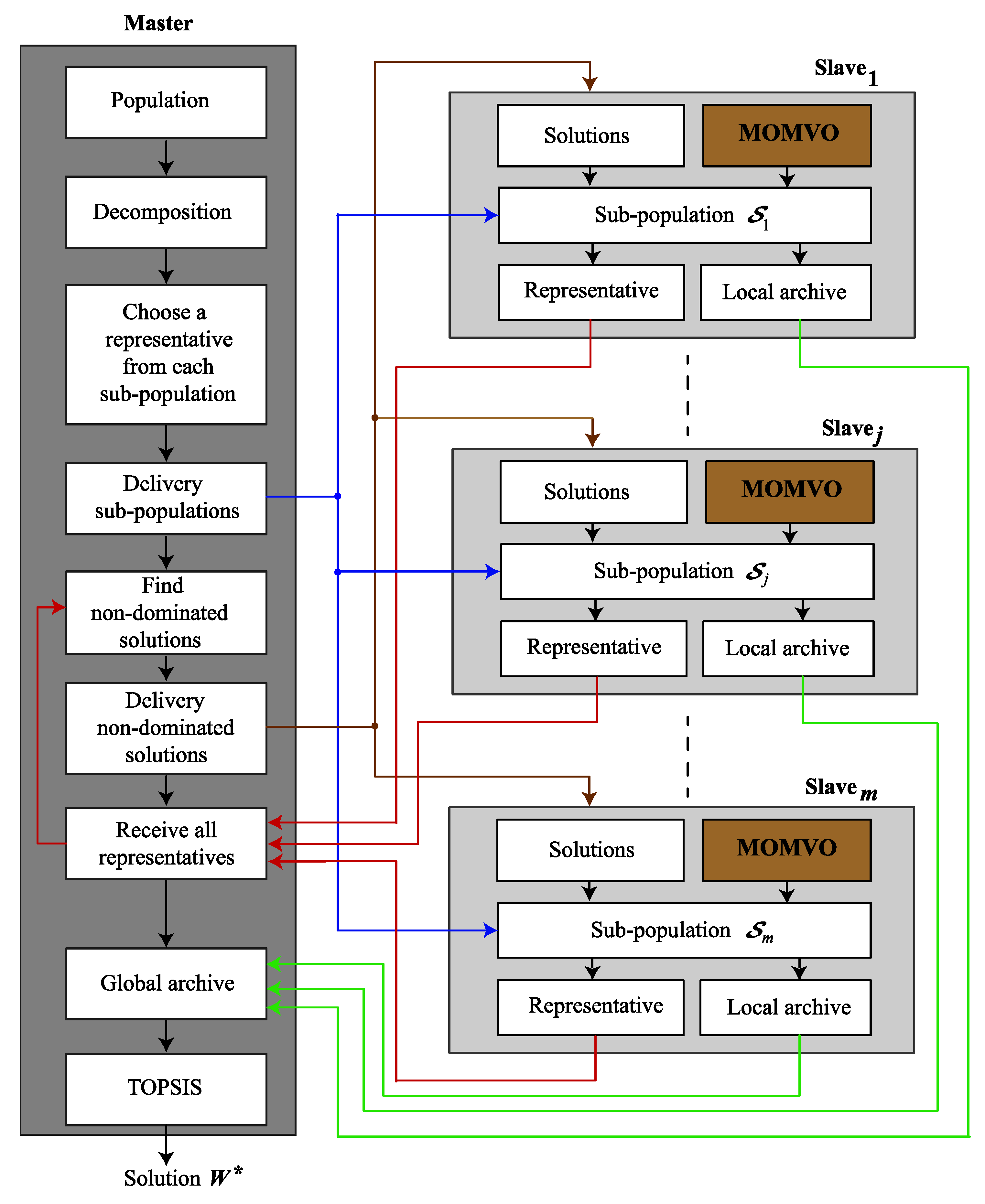
In this paper, a master–slave model is proposed for the MOMVO algorithm parallelization as shown in Figure 7. In this proposed shared memory model, one of the CPU cores is selected as the master and the other ones are defined as the slaves [32].
The master processor will be responsible for initializing the population with cardinality n p o p and breaking it down into m subpopulations denoted as S 1 , S 2 , , S m . Each subswarm of the entire MOMVO population is granted to a corresponding slave and a representative of each of them is selected by the roulette technique and sent to the master core, as shown in Figure 7.
In this work, the parallelization mechanism is introduced to simultaneously evolve all the subpopulations in the different cores, which can minimize the execution time. Each slave is designed to evolve the allocated subpopulation by applying a MOMVO code, as described in Algorithm 1, and independently search for the set of Pareto solutions. After an evolution cycle, each slave sends to the master the best solution retained by the roulette technique [49]. The master receives the solutions from all slaves and returns the nondominated ones to each for a new cycle. After that, each slave replaces its worst solutions with the solutions received from the master which are considered as best ones. The master checks the stopping condition; if it is reached, this process stops, and the slaves send their local Pareto fronts to the core representing the master. Such a master merges the received Pareto fronts and removes the repeated solutions to make a set of nondominated solutions and, therefore, a global Pareto front. Algorithm 2 provides a pseudocode for the proposed parallel processing PMOMVO algorithm.
Algorithm 2: PMOMVO
Master process
1.
Randomly initialize n p o p agents of the population.
2.
Decompose the population into m subswarms denoted as S 1 , S 2 , , S m .
3.
Randomly choose a representative solution from each subswarm.
4.
Send each subswarm to a corresponding slave.
5.
Cycle = 0.
6.
While termination criterion = false do
Parallel for j = 1 to m slaves
Find the nondominated solutions among the representatives of the slaves.
Send to the slaves the nondominant solutions.
Waiting for slaves.
Receive all representatives of subswarms from the slaves.
End Parallel for
Cycle = Cycle+1.
End While
7.
Merge all subpopulations’ Pareto fronts in a single one.
8.
Use the multicriteria decision making TOPSIS method to find the optimal solution.
Slave [j] process
9.
While true do
Receive the solutions from the master process.
Update the worst solutions with those received from the master.
Execute the MOMVO algorithm on each subswarm S j .
Select and send the representative of each subswarm S j to the master process.
End While

5. Simulation Results and Discussion

5.1. Software Environment for Parallel Computing

For a practical implementation of the parallel MOMVO algorithm, the hardware architecture on which the program will be executed and the software environment associated with such architecture are key elements. In this work, a multicore CPU architecture was adopted for parallelization. A computer with a Core i5 processor with 12 cores at 2.90 GHz and 8.00 GB of RAM was used. In such a parallel architecture, the multiple CPU cores of a shared memory machine can operate in parallel and share the same memory space. The “Parallel Computing Toolbox” of the MATLAB environment was investigated to provide the easiest parallel programming avenue [50]. In this paper, the simplest “Parfor” structure of the MATLAB software tool was used to illustrate this functionality. The number of iterations of the “Parfor” loop was equal to the number of workers who performed the iterations independently of each other and evolved in parallel, i.e., one per subpopulation.

5.2. Numerical Experimentations and ANOVA Tests

In order to illustrate the effectiveness of the proposed PMOMVO algorithm for the formulated path planning problem, six variants of such an algorithm were executed under various flight scenarios with an increased number of moving obstacles, as shown in Table 2. These PMOMVO variants implement parallel algorithms with different subpopulations equal to 2, 4, 6, 8, 10, and 12 according to the available cores of the used CPU-based master–slave architecture. For the rest of the paper, these variants are denoted as PMOMVO-2, PMOMVO-4, PMOMVO-6, PMOMVO-8, PMOMVO-10, and PMOMVO-12. The control parameters of the reported algorithms are set as ρ min = 0.2 , ρ max = 1 , n p o p = 50 and n i t e r = 100 .
All PMOMVO variants were run 20 independent times on the formulated path planning problem (16). For all experimentations, the PMOMVO variants were compared to the normal MOMVO as described by Algorithm 1. The effects of the main design parameters, i.e., the number of times that slaves shared their best solutions l 0 , 1 , 3 , 7 , 9 , called the sharing rate of better solutions, and the number of slaves in the parallel CPU architecture m 2 , 4 , 6 , 8 , 10 , 12 were analyzed and discussed. In order to evaluate the performance of the PMOMVO algorithms in terms of convergence capability and Pareto nondominated solutions diversity, the metrics hyper volume (HV) [51], maximum spread (MS) [52], and hole relative size (HRS) [53] were considered. The results of these performance measurements are summarized in Table 3, Table 4 and Table 5, respectively.
By observing these experimentations, one can note that for the HV and MS performance metrics, increasing the number of slaves and Pareto best solution sharing rates leads to a clear superiority of the PMOMVO algorithms in terms of obtained nondominated solution diversity. Moreover, since the HRS metric calculates the largest spacing of nondominated solutions on a Pareto front, the obtained low values of such a performance measurement for the proposed PMOMVO solvers lead to better uniformity of the compromise surfaces. As shown in Table 5, the numerical results show that for all reported PMOMVO variants, the HRS values are decreased by increasing the sharing rates of the better solutions.
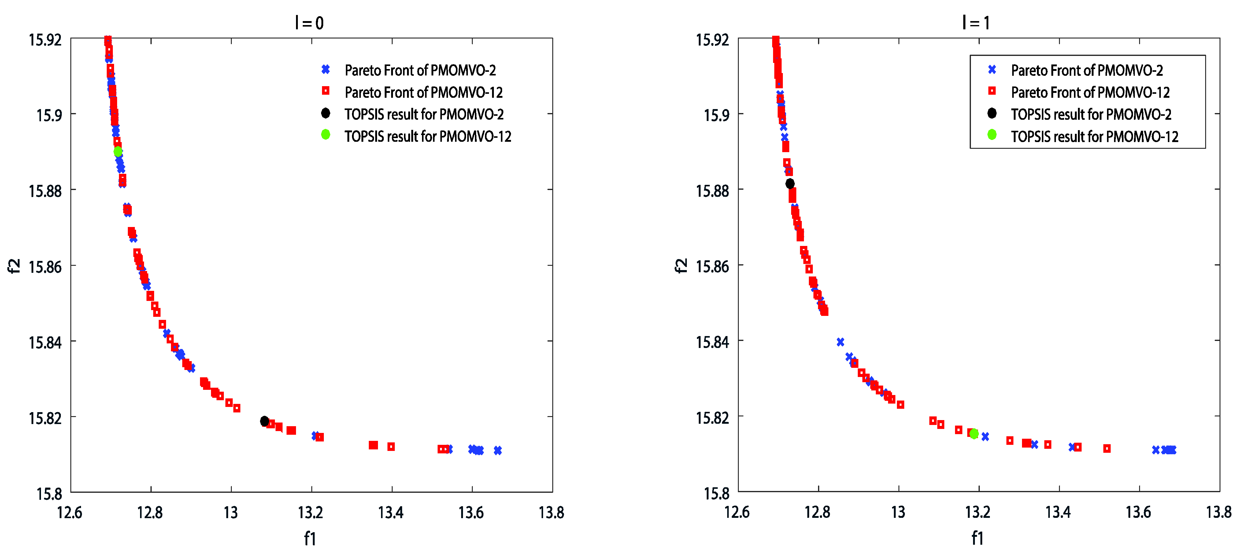
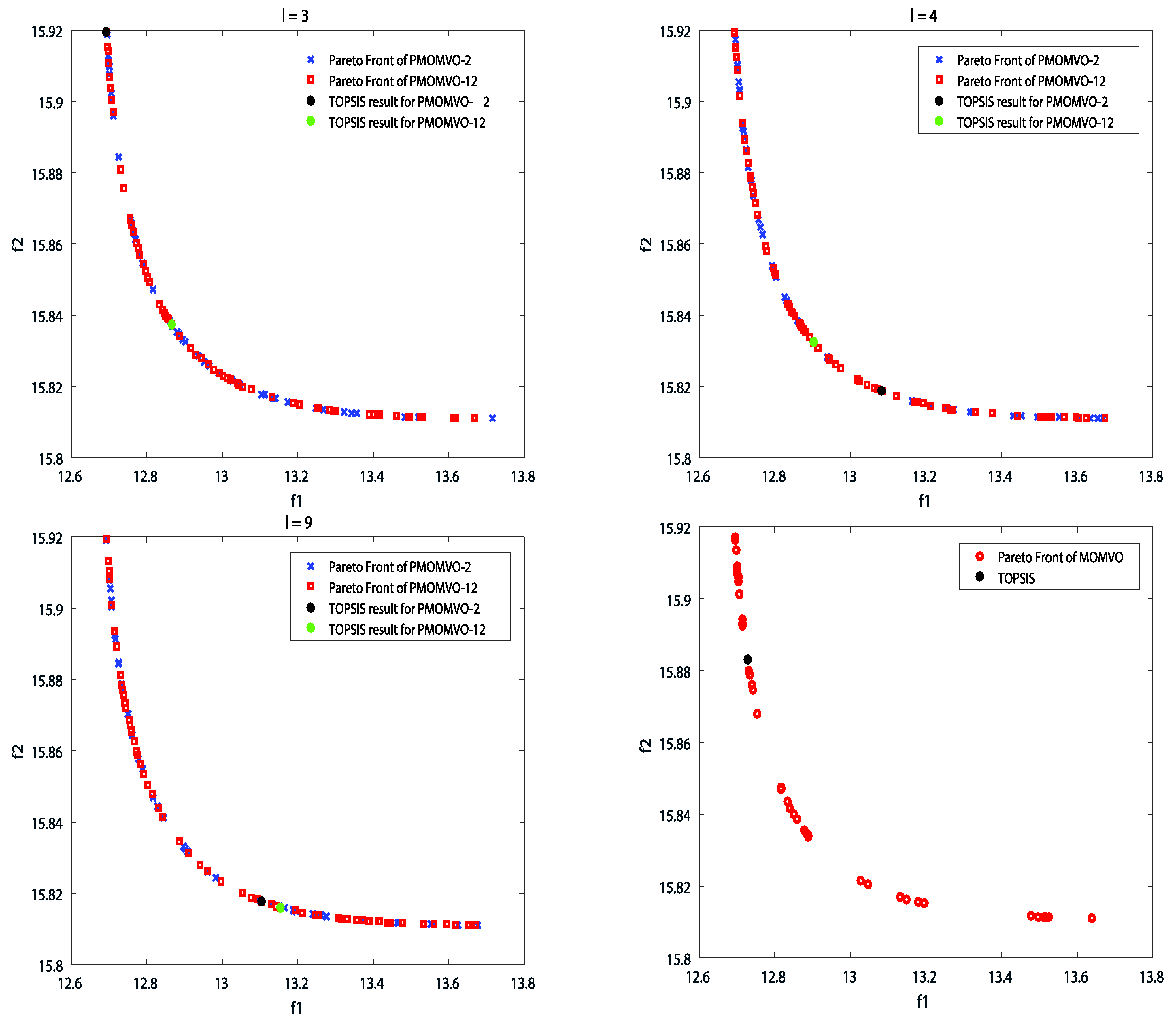
Figure 8 illustrates the set of Pareto solutions obtained by the MOMVO and PMOMVO algorithms corresponding to the mean case of the optimization. Looking at these results, one can observe the large gaps in the topology distribution of Pareto fronts for the low values of the sharing rates l = 0 , l = 1 , and l = 3 . However, for the high solution sharing rate l = 9 , the distribution of the nondominated solutions along the compromise surface is more uniform. According to these demonstrative results, the number of times that slaves share information with each other clearly influences the uniformity of the obtained Pareto front. The higher the l value, the more the distribution of Pareto solutions approximates a uniform distribution. In addition, the performance of the PMOMVO variants, especially those with the highest number of slaves, surpasses the standard MOMVO in terms of solution distribution uniformity.
Let us consider the evaluation and analysis of the generated UAV global paths. To discuss the performance of the PMOMVO algorithm in solving the dynamic path planning problem, experimentations were performed considering the commonly used performance criteria flight time (FT) and straight-line rate (SLR) [32]. The ability to avoid collisions with moving obstacles in the considered dynamic environment was also investigated. Numerical experimentations carried out for 20 independent executions led to the optimization results of Table 6 and Table 7. In terms of the traveled path length, the smaller the SLR metric, the better the PMOMVO-based planner efficiency. Similarly for the FT performance criterion, the lower the elapsed time, the better the optimization algorithm in terms of navigation speed and planning time management.
In order to statistically analyze these results, nonparametric ANOVA statistics in the sense of Friedman and Fisher’s LSD posthoc tests were carried out while considering the two performance criteria SLR and FT [54]. The related statistical results are summarized in Table 8, Table 9, Table 10 and Table 11. The performance of the reported parallel PMOMVO algorithms was analyzed through the considered flight scenarios of Table 2. The Iman–Davenport extension of the Friedman test provides the statistics F F 1 = 38.424 and F F 2 = 83.500 for the SLR and FT criteria, respectively. For the seven algorithms ( μ = 7 ) and five path planning scenarios ( σ = 5 ), the critical F-statistics value at 95% of significance and with μ 1 and μ 1 σ 1 degrees of freedom is equal to F 6 , 24 , 0.05 = 2.5082 < F F 1 < F F 2 . Therefore, the null hypothesis is rejected and there are significant differences between the competing PMOMVO solvers.
Fisher’s LSD posthoc test was applied to find out which PMOMVO-based planning algorithms differ from others [54]. Table 10 and Table 11 summarize the paired comparisons of all reported algorithms for the SLR and FT performance indices, respectively. The critical values computed for the absolute difference of the rank sums of the two algorithms are equal to 4.0124 for the SLR criterion and 2.7939 for the FT criterion, respectively. The bold and underlined values indicate significant differences between the performances of the competing PMOMVO algorithms. From these performed statistical tests and analyses as well as the Friedman ranking of the proposed PMOMVO-based planners, one can observe that the variants with the highest number of CPU multicores slaves, i.e., PMOMVO-10 and PMOMVO-12, outperform the standard MOMVO one as well as the other PMOMVO algorithms with the lower number of slaves. However, in terms of processing time, one can observe, according to the results of Table 7, that the PMOMVO-6 algorithm is the best variant regarding the obtained low values of the FT metrics. Such a variant of the PMOMVO algorithm can be retained for the rest of developments as the faster and more efficient solution to the UAV path planning problem in the considered dynamic 3D environment with moving obstacles.
Regarding the ability of the proposed technique to avoid collisions with moving obstacles, other experiments were conducted. The usefulness of the proposed parallel processing PMOMVO-based path planning approach was tested through three flight instances with the same starting and destination positions and moving obstacle number but with different positions and motion speeds of the dynamic threats, as shown in Table 12. The case of design using the best compromise of computation time and low slaves in the multicore CPU architecture, i.e., the PMOMVO-6 variant, was considered for the demonstrative results.
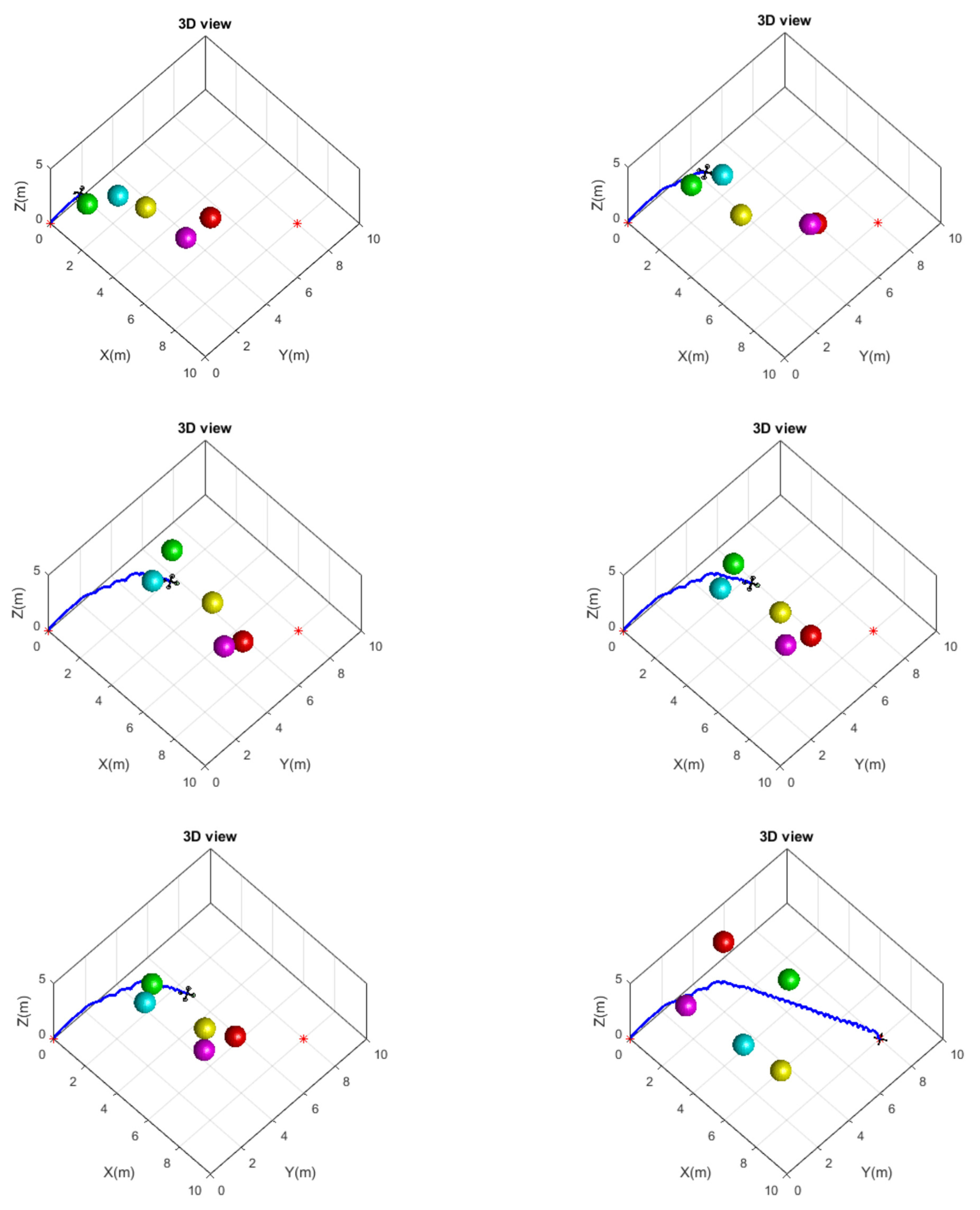
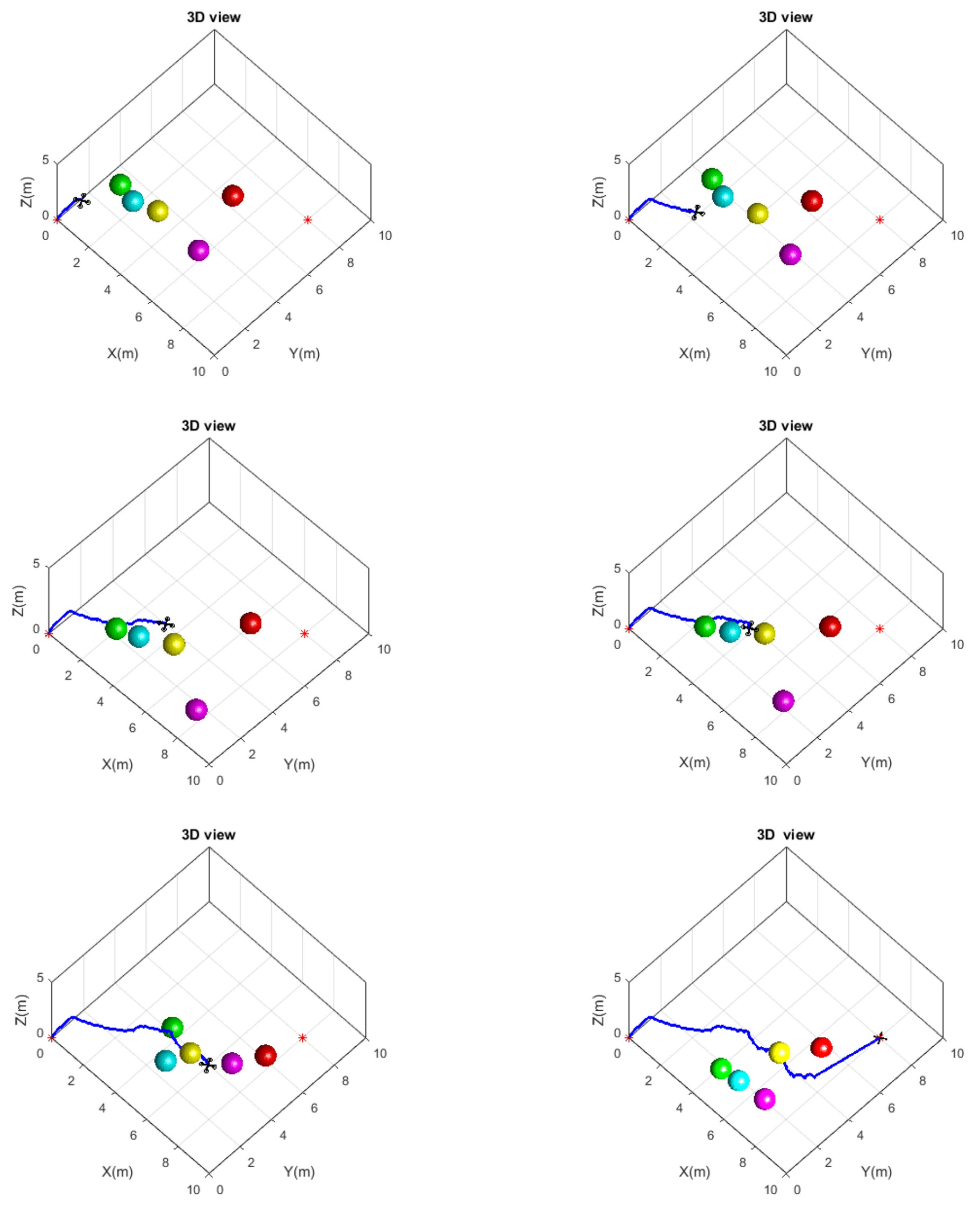
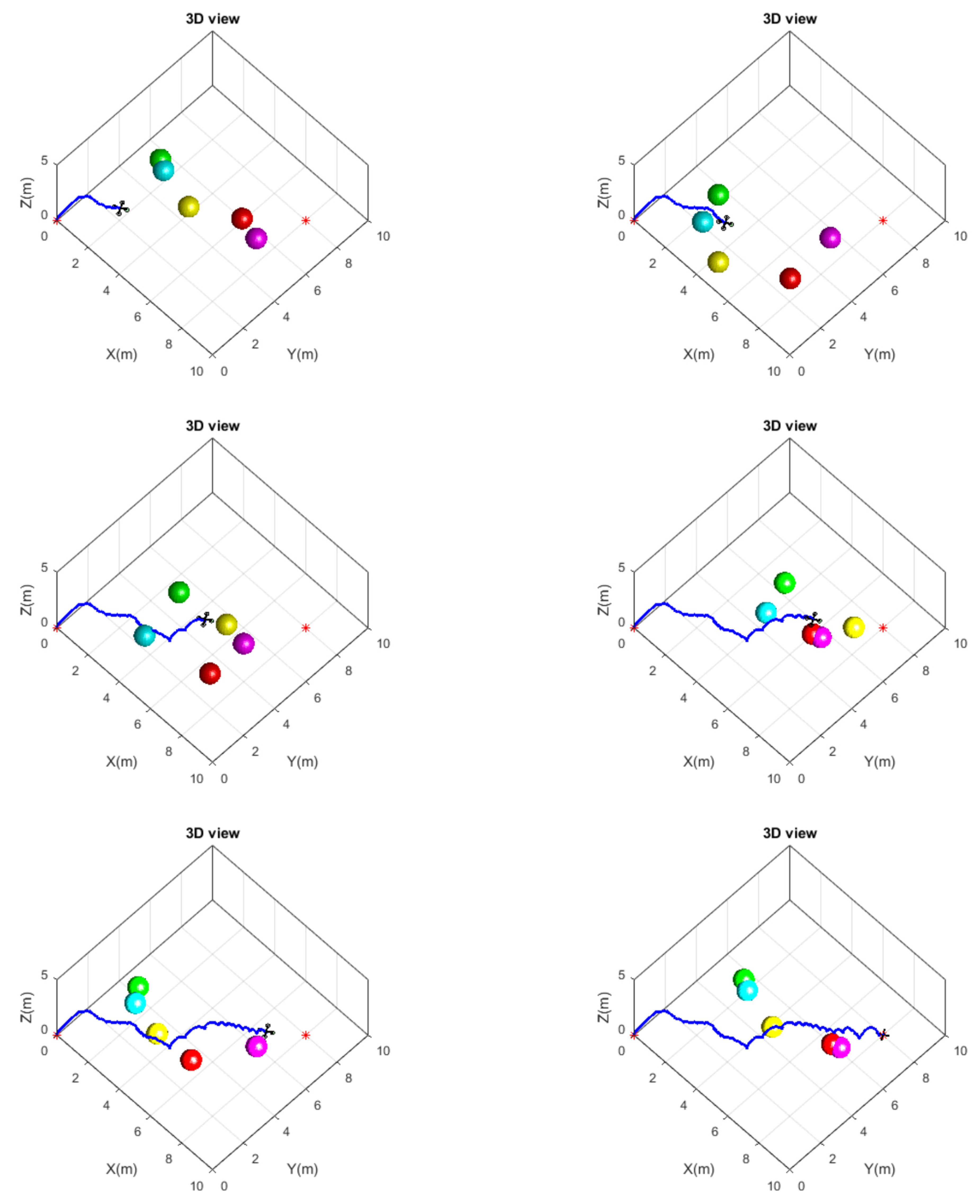
Figure 9, Figure 10 and Figure 11 present the simulation results of the planned paths over the different scenarios. Each situation gives the result of dynamic path planning where the UAV positions are captured relatively at different times of the navigation process. These demonstrative results show the collision-free abilities facing moving obstacles with different initial positions and motion speeds. Changing the position and motion speed of the moving obstacles affects the 3D planned path, which further improves the effectiveness and superiority of the proposed PMOMVO-based planning approach under moving obstacles.
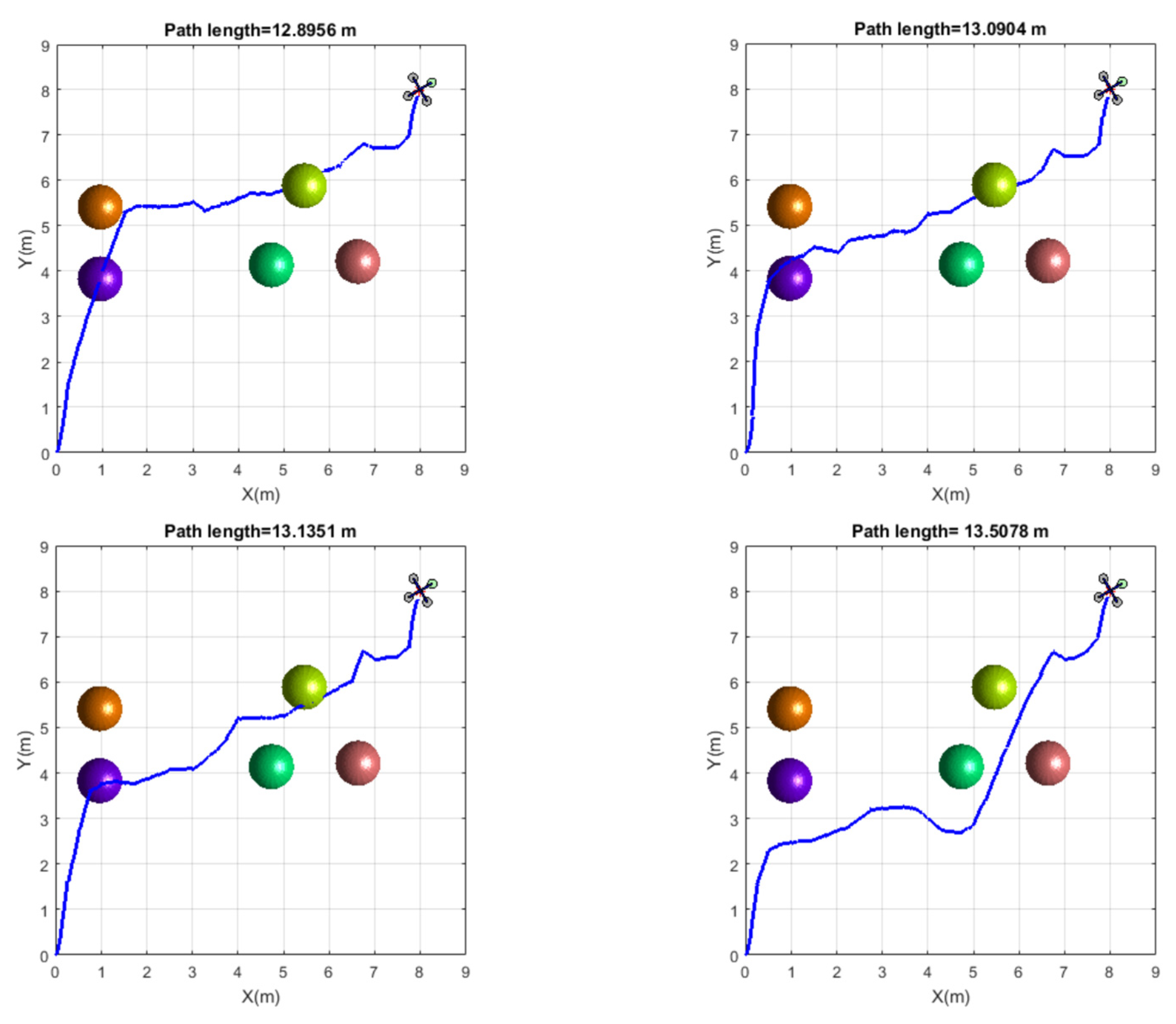
To discuss the quality of the obtained solutions, additional simulation results were carried out, as shown in Figure 12. The same flight scenario was considered, and four runs of the PMOMVO-based planner were made. Based on this illustration, one can observe that with the same conditions of a path planning scenario, i.e., same number of obstacles, same start and destination positions, etc., the proposed PMOMVO-based planner as a metaheuristics-based design approach gives a nonreproducible result but still a good feasible solution for the addressed optimization problem. Among all these results, one can choose the best in terms of the shortness of the flyable path and collision avoidance capability regarding the moving obstacles. Through these comparable results and the high reproducibility behavior of the proposed PMOMVO algorithm, argued by the obtained small values of STD metrics, one can observe the minor and negligible deviations between all these obtained results. So, the optimality of the obtained solution can neither be affirmed nor checked theoretically, but such a solution remains quite feasible and of good quality.

5.3. Computation Tims Analysis and Comparison

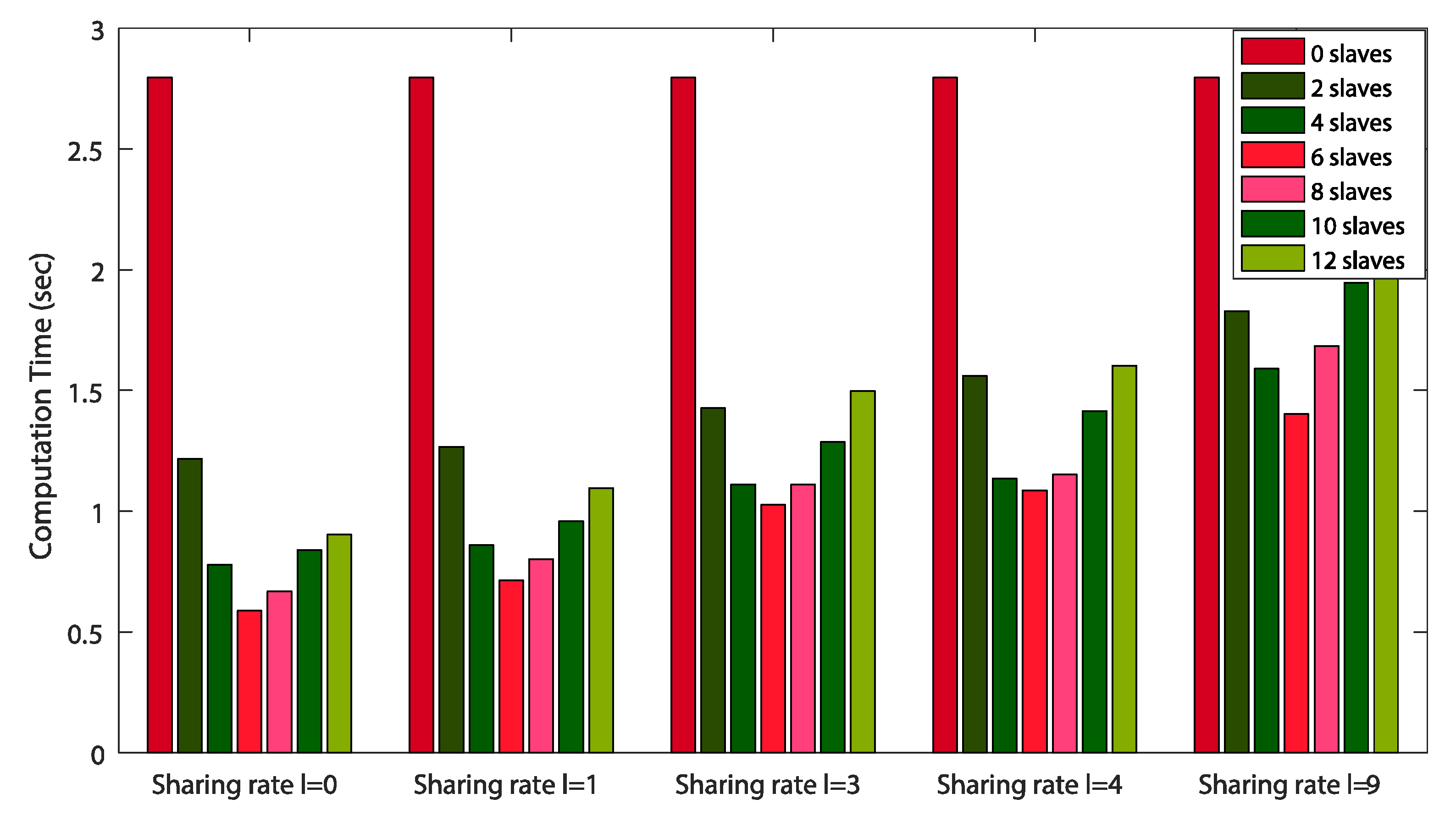
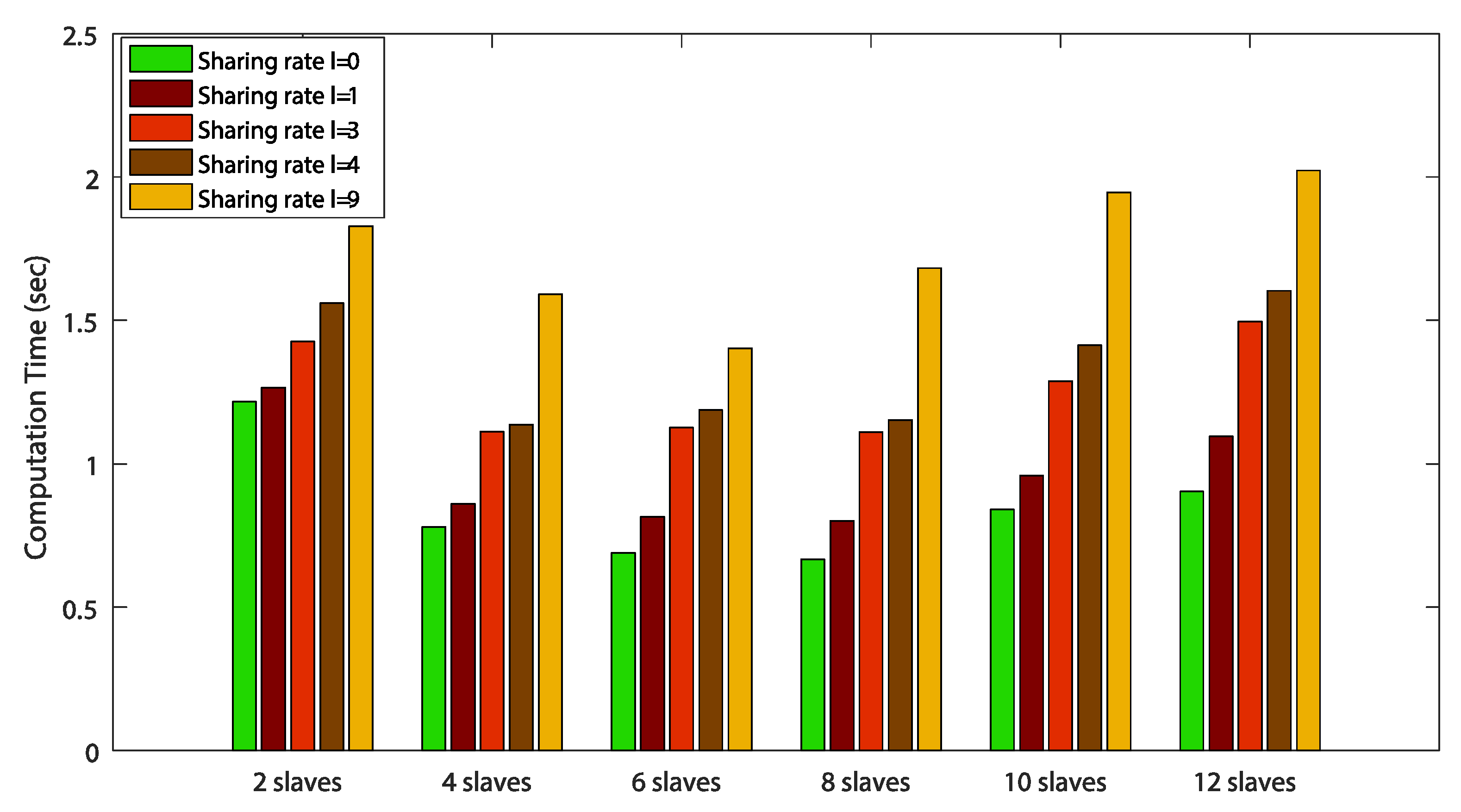
The performance of the proposed PMOMVO variants is discussed in terms of computation time consumption. The algorithm’s execution time presents a key element for any efficient collision-free path planner in a real-world application of UAV navigation. First, it is important to note that the two main design parameters of the proposed parallel-processing-based algorithm are the solution sharing rate and the number of slaves. Numerical experimentations were carried out to show the effect of increasing the solution sharing rate of slaves in each variant of the PMOMVO algorithm. Figure 13 and Figure 14 show the evolution of the computation time metric over the sharing rate configuration and slave number variation, respectively. These demonstrative results highlight the superiority of the proposed PMOMVO algorithms compared to the MOMVO standard one. Based on these results, one can observe clearly the influence of the sharing rates and slave numbers on the performance of the proposed planning strategy in terms of computation times and execution fastness. As the number of slaves increases, the execution time decreases up to a certain number of slaves and then gradually increases. The reason for the increase in computation time for a high number of slaves is that the processing time related to the affected computations is not enough, and the master–slave communications require more time. In this study, one can conclude that the variant of the PMOMVO algorithm that runs with a six-slave-based multicore CPU architecture remains the best solver in terms of computing speed.
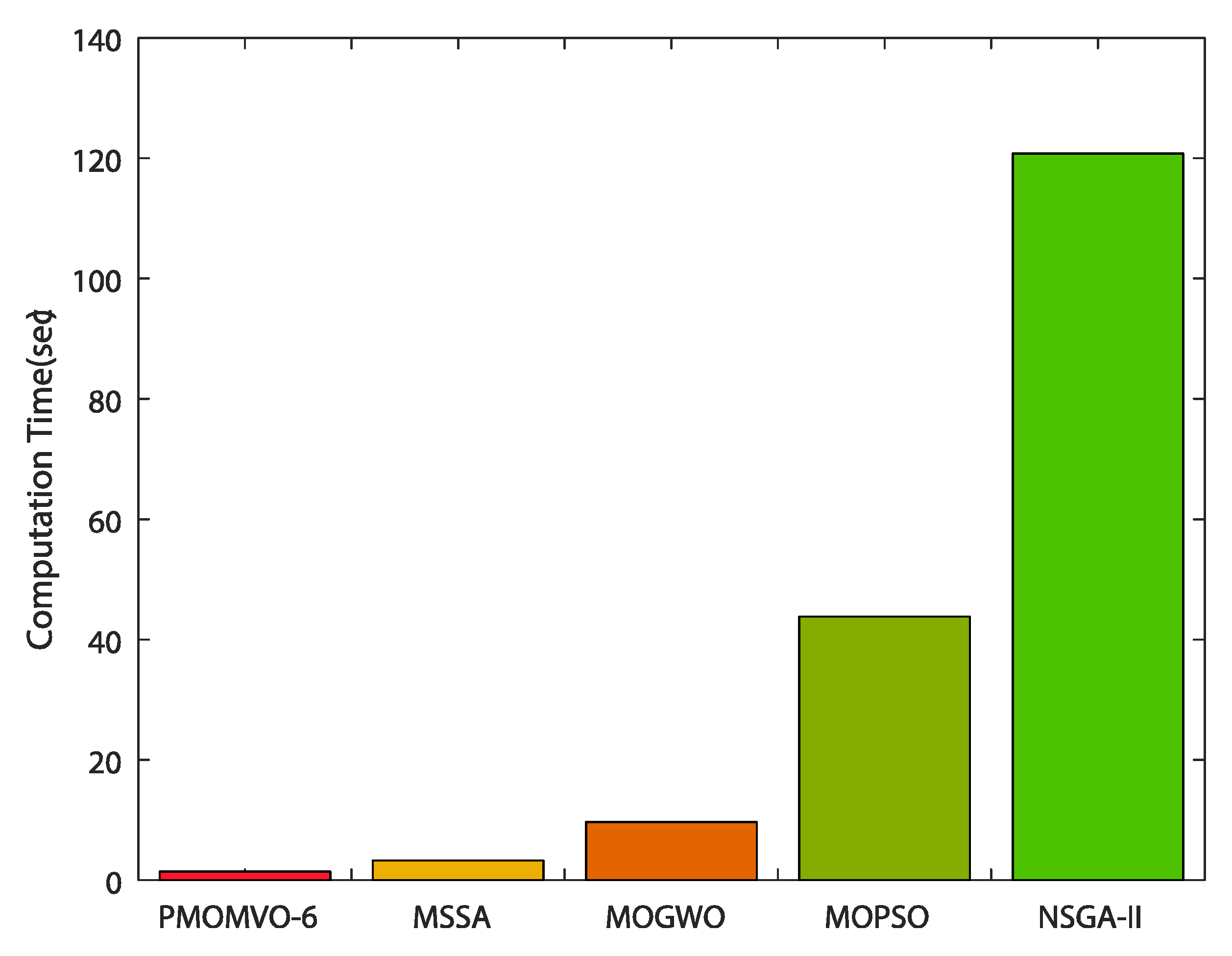
On the other hand, in order to further show the superiority of the proposed parallel PMOMVO algorithm, a comparative study of the computation times was carried out, as depicted in Figure 15. Other extensively used multiobjective optimization algorithms, namely the salp swarm algorithm (MSSA) [55], grey wolf optimizer (MOGWO) [56], nondominated sorting genetic algorithm II (NSGA-II) [57], and particle swarm optimization (MOPSO) [58] were considered for such a comparison. Retained as the most powerful variant of the PMOMVO algorithm in terms of computation time, the PMOMVO-6 optimizer largely outperformed all reported MSSA, MOGWO, MOPSO, and NSGA-II algorithms.

5.4. Parameters Sensitivity Analysis

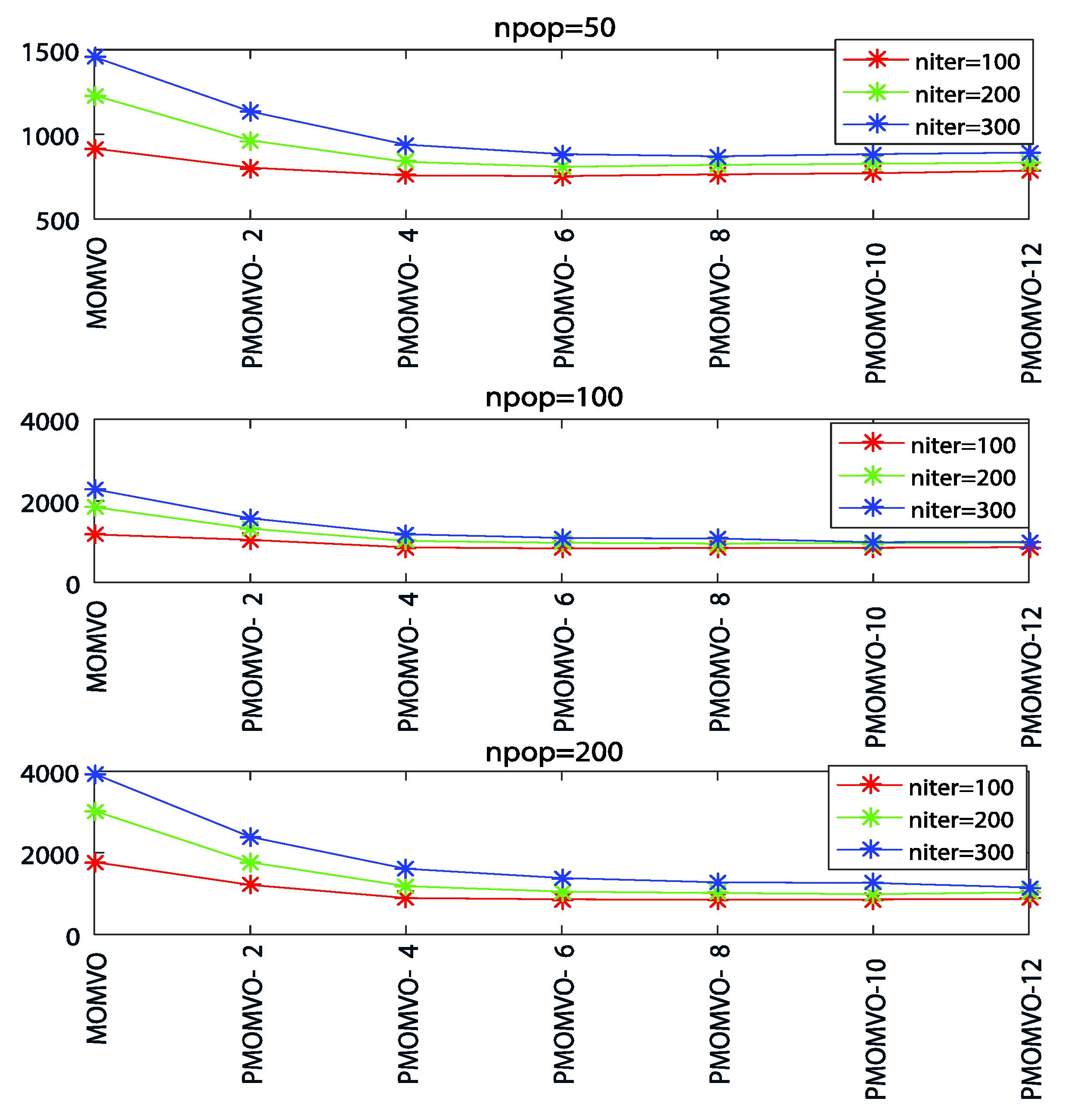
As for any path planning approach using unconventional and nonreproducible algorithms, the influence of main control parameters should be analyzed and discussed. The algorithm sensitivity is investigated through numerical experimentations performed with randomly chosen sets of population size n p o p and iterations n i t e r . The solution sharing rate of PMOMVO slaves is set as l = 9 . Table 13 and Table 14 summarize the optimization results obtained in Scenario 5 of Table 2 while considering path length (m) and flight time (s) as performance metrics. From these demonstrative results, increasing the population cardinality and iterations does not have a significant effect on planning performance in terms of obtained collision-free path lengths, unlike the flight time which is further increased.
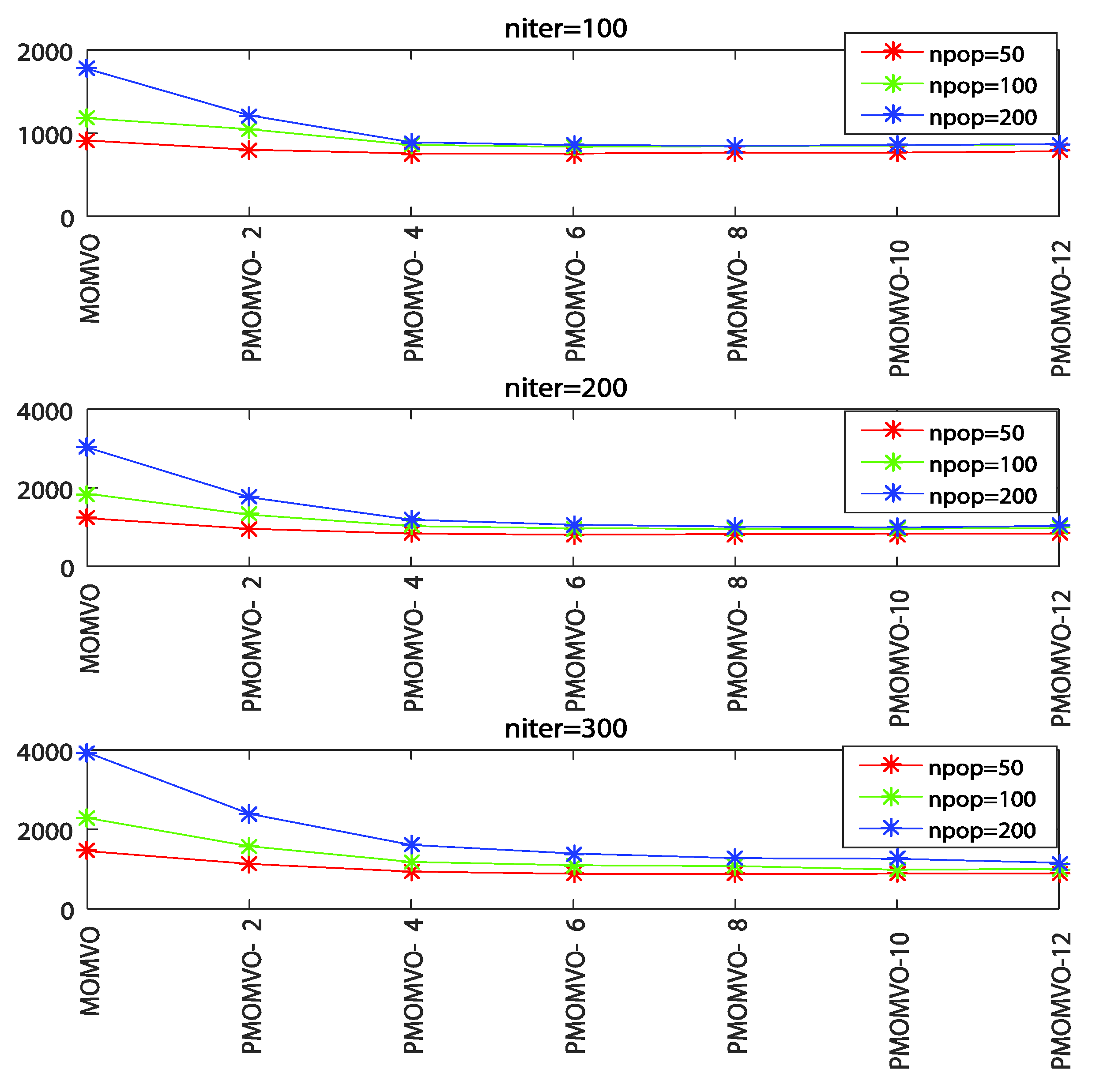
Roughly, the superiority of the improved MOMVO algorithms over the classical MOMVO one is demonstrated with a larger population size and higher number of iterations. Obviously, with the increase in the computation time, which is due to the increase in the number of iterations and size of the population, an increase in the number of slaves is necessary to better manage the complexity of the dynamic path planning task. The effects of these two main control parameters of PMOMVO algorithms are further illustrated as shown in Figure 16 and Figure 17. Based on these experimentations and results, one can consider that the proposed parallelization-based improvements of the classical MOMVO algorithm perform better for complex path planning problems that require significant computation time.

5.5. Comparison with Other Metaheuristics Algorithms

To analyze the performance of the proposed PMOMVO algorithms, mainly the PMOMVO-6 variant, in terms of path length (SLR) and flight time (FT) performance, the multiobjective metaheuristics algorithms MSSA, MOGWO, NSGA-II, and MOPSO already retained for the comparison of computation times were reconsidered again. These optimizers run with the following control parameters:
  • − MSSA [55]: without control parameters (parameters-free algorithm).
  • − MOGWO [56]: grid inflation 0.1, number of grids per dimension 10, leader selection pressure 4, and extra repository member selection pressure 2.
  • − NSGA-II [57]: crossover probability 0.7, mutation probability 0.4, and mutation rate 0.02.
  • − MOPSO [58]: social and cognitive parameters 2, grid inflation 0.1, leader selection pressure parameter 2, and number of grids per dimension 7.
The common control parameters of the compared multiobjective algorithms were set as n i t e r = 100 and n p o p = 50 . All optimizers were run independently 20 times according to Scenario 5 of the path planning with moving obstacles given in Table 2. The experimentation results of the comparison are summarized in Table 15. Based on these demonstrative results, one can observe that the proposed parallel processing PMOMVO-6 variant outperformed all reported algorithms with lower values for SLR (m) and FT (sec) metrics. The STD statistics were minimal in the case of optimization with the PMOMVO-6 algorithm. The superiority of such a parallel optimizer is further improved in terms of solution quality, reproducibility capacity, and computational time fastness.

6. Conclusions

In this paper, a new parallel processing variant of the multiobjective multiverse optimizer (PMOMVO) based on a master–slave multi-core CPU model has been proposed and successfully applied to solve the UAV path planning problem in a dynamic environment with moving obstacles. To overcome the limits and drawbacks of the standard MOMVO algorithms, particularly in terms of prohibitive computation time consumption, an efficient processing parallelization based on a master–slave CPU multicore architecture was introduced and successfully implemented. The reduction in computation time of the parallel PMOMVO algorithm contributed to the effectiveness of the proposed path planning strategy in terms of avoiding collisions with moving obstacles and narrow pass zones. Such a dynamic path planning problem was reformulated based on new ideas of collision avoidance with a moving body in a 3D space. The drone became able to respect the resulting dynamic constraints of navigation and processing time consumption and, consequently, reacted quickly to such changes in the environment.
According to the available cores of a given hardware CPU architecture and the number of partitioned MOMVO subpopulations, six variants of the parallel algorithm denoted as PMOMVO-2, PMOMVO-4, PMOMVO-6, PMOMVO-8, PMOMVO-10, and PMOMVO-12 were designed. Each slave of the proposed multicore CPU architecture was implemented to evolve the allocated subpopulation by applying a MOMVO algorithm and seding the best-selected solutions after each cycle of evolution to the master. The master received the solutions and sent to each slave the Pareto nondominated ones for a new cycle. A modified TOPSIS technique was used to select solutions in the sense of Pareto. In this study, one can observe that the variant of the PMOMVO algorithm running with six slaves, i.e., PMOMVO-6, outperformed all other compared algorithms in terms of computation time performance and solution quality. Demonstrative results and nonparametric ANOVA statistical analyses based on Friedman’s and Fisher’s LSD posthoc tests show the effectiveness and superiority of the proposed parallel processing PMOMVO algorithms for UAV path planning with collision avoidance problems in dynamic 3D environments.
Future work will focus firstly on the comparison of the proposed parallel processing PMOMVO-based path planning approach with introduced enhancements in terms of computation time reduction and moving threats collision avoidance with other popular path planning techniques, such as those using the concepts of rapidly exploding random tree (RRT). Secondly, the real-world implementation of the proposed metaheuristics-based path planning algorithm will be investigated within an indoor application using the laboratory-available Parrot AR. Drone 2.0 prototype.

Author Contributions

Conceptualization, R.J. and S.B.; methodology, S.B.; software, R.J.; validation, M.A.-D., H.R. and S.B.; formal analysis, H.R.; investigation, R.J. and S.B.; resources, R.J.; data curation, M.A.-D.; writing—original draft preparation, R.J.; writing—review and editing, S.B. and H.R.; visualization, M.A.-D.; supervision, S.B.; project administration, H.R.; funding acquisition, H.R. and M.A.-D. All authors have read and agreed to the published version of the manuscript.

Funding

This research received no external funding.

Informed Consent Statement

Not applicable.

Data Availability Statement

No new data were created or analyzed in this study.

Acknowledgments

The authors acknowledge the support of King Fahd University of Petroleum and Minerals, Saudi Arabia.

Conflicts of Interest

The authors declare no conflict of interest.

References

  1. Mohsan, S.A.H.; Khan, M.A.; Noor, F.; Ullah, I.; Alsharif, M.H. Towards the unmanned aerial vehicles (UAVs): A comprehensive review. Drones 2022, 6, 147. [Google Scholar] [CrossRef]
  2. Abro, G.E.M.; Zulkifli, S.A.B.M.; Masood, R.J.; Asirvadam, V.S.; Louati, A. Comprehensive review of UAV detection, security, and communication advancements to prevent threats. Drones 2022, 6, 284. [Google Scholar] [CrossRef]
  3. Yasin, J.N.; Mohamed, S.A.S.; Haghbayan, M.-H.; Heikkonen, J.; Tenhunen, H.; PLoSila, J. Unmanned aerial vehicles (UAVs): Collision avoidance systems and approaches. IEEE Access 2020, 8, 105139–105155. [Google Scholar] [CrossRef]
  4. Huang, S.; Teo, R.S.H.; Tan, K.K. Collision avoidance of multi unmanned aerial vehicles: A review. Annu. Rev. Control 2019, 48, 147–164. [Google Scholar] [CrossRef]
  5. Mohanan, M.G.; Salgoankar, A. A survey of robotic motion planning in dynamic environments. Robot. Auton. Syst. 2018, 100, 171–185. [Google Scholar] [CrossRef]
  6. Jones, M.R.; Djahel, S.; Welsh, K. Path-planning for unmanned aerial vehicles with environment complexity considerations: A survey. ACM Comput. Surv. 2022. [Google Scholar] [CrossRef]
  7. Aggarwal, S.; Kumar, N. Path planning techniques for unmanned aerial vehicles: A review, solutions, and challenges. Comput. Commun. 2019, 149, 270–299. [Google Scholar] [CrossRef]
  8. Chen, X.; Zhao, M.; Yin, L. Dynamic path planning of the UAV avoiding static and moving obstacles. J. Intell. Robot. Syst. 2020, 99, 909–931. [Google Scholar] [CrossRef]
  9. Gan, X.; Wu, Y.; Liu, P.; Wang, Q. Dynamic Collision Avoidance Zone Modeling Method Based on UAV Emergency Collision Avoidance Trajectory. In Proceedings of the 2020 IEEE International Conference on Artificial Intelligence and Information Systems, Dalian, China, 20–22 March 2020. [Google Scholar]
  10. Wei, R.; Xu, Z.; Zhang, Q.; Zhou, K.; Ni, T. Analysis and Application to Collision Avoidance Stability of Cognitive UAV. In Proceedings of the 2018 IEEE CSAA Guidance, Navigation and Control Conference, Xiamen, China, 10–12 August 2018. [Google Scholar]
  11. Corraro, F.; Corraro, G.; Cuciniello, G.; Garbarino, L. Unmanned aircraft collision detection and avoidance for dealing with multiple hazards. Aerospace 2022, 9, 190. [Google Scholar] [CrossRef]
  12. Lihua, Z.; Xianghong, C.; Fuh-Gwo, Y. A 3D collision avoidance strategy for UAV with physical constraints. Measurement 2015, 77, 40–49. [Google Scholar] [CrossRef]
  13. Blasi, L.; D’Amato, E.; Mattei, M.; Notaro, I. Path planning and real-time collision avoidance based on the essential visibility graph. Appl. Sci. 2020, 10, 5613. [Google Scholar] [CrossRef]
  14. Ma, R.; Ma, W.; Chen, X.; Li, J. Real-Time Obstacle Avoidance for Fixed-Wing Vehicles in Complex Environment. In Proceedings of the IEEE Chinese Guidance, Navigation and Control Conference, Nanjing, China, 12–14 August 2016. [Google Scholar]
  15. Lu, L.; Zong, C.; Lei, X.; Chen, B.; Zhao, P. Fixed-wing UAV path planning in a dynamic environment via dynamic RRT algorithm. In Mechanism and Machine Science; Asian MMS CCMMS, Lecture Notes in Electrical Engineering; Zhang, X., Wang, N., Huang, Y., Eds.; Springer: Singapore, 2017; Volume 408, pp. 271–282. [Google Scholar]
  16. Zu, W.; Fan, G.; Gao, Y.; Ma, Y.; Zhang, H.; Zeng, H. Multi-UAVs Cooperative Path Planning Method Based on Improved RRT Algorithm. In Proceedings of the 2018 IEEE International Conference on Mechatronics and Automation, Changchun, China, 5–8 August 2018. [Google Scholar]
  17. Israr, A.; Ali, Z.A.; Alkhammash, E.H.; Jussila, J.J. Optimization methods applied to motion planning of unmanned aerial vehicles: A review. Drones 2022, 6, 126. [Google Scholar] [CrossRef]
  18. Huang, C.; Lan, Y.; Liu, Y.; Zhou, W.; Pei, H.; Yang, L.; Cheng, Y.; Hao, Y.; Peng, Y. A new dynamic path planning approach for unmanned aerial vehicles. Complexity 2018, 2018, 8420294. [Google Scholar] [CrossRef]
  19. Ge, F.; Li, K.; Han, Y.; Xu, W.; Wang, Y. Path planning of UAV for oilfield inspections in a three-dimensional dynamic environment with moving obstacles based on an improved pigeon-inspired optimization algorithm. Appl. Intell. 2020, 50, 2800–2817. [Google Scholar] [CrossRef]
  20. Zhang, B.; Duan, H. Three-dimensional path planning for uninhabited combat aerial vehicle based on predator-prey pigeon-inspired optimization in dynamic environment. IEEE ACM Trans. Comput. Biol. Bioinform. 2017, 14, 97–107. [Google Scholar] [CrossRef]
  21. Tian, G.; Zhang, L.; Bai, X.; Wang, B. Real-time Dynamic Track Planning of Multi-UAV Formation Based on Improved Artificial Bee Colony Algorithm. In Proceedings of the 37th Chinese Control Conference, Wuhan, China, 25–27 July 2018. [Google Scholar]
  22. Zajac, S.; Huber, S. Objectives and methods in multi-objective routing problems: A survey and classification scheme. Eur. J. Oper. Res. 2020, 290, 1–25. [Google Scholar] [CrossRef]
  23. Zhang, Y.; Gong, D.-W.; Zhang, J.-H. Robot path planning in uncertain environment using multi-objective particle swarm optimization. Neurocomputing 2013, 103, 172–185. [Google Scholar] [CrossRef]
  24. Jarray, R.; Al-Dhaifallah, M.; Rezk, H.; Bouallègue, S. Path planning of quadrotors in a dynamic environment using a multi-criteria multi-verse optimizer. Comput. Mater. Contin. 2021, 69, 2159–2180. [Google Scholar]
  25. Jarray, R.; Bouallègue, S. Multi-criteria path planning of unmanned aerial vehicles through a combined multi-verse and decision-making methods. Int. J. Sci. Res. Eng. Technol. 2021, 15, 1–8. [Google Scholar]
  26. Jarray, R.; Bouallègue, S. Multi-verse algorithm-based approach for multi-criteria path planning of unmanned aerial vehicles. Int. J. Adv. Comput. Sci. Appl. 2020, 11, 324–334. [Google Scholar] [CrossRef]
  27. Paikray, H.K.; Das, P.K.; Panda, S. Optimal path planning of multi-robot in dynamic environment using hybridization of meta-heuristic algorithm. Int. J. Intell. Robot. Appl. 2022, 6, 625–667. [Google Scholar] [CrossRef]
  28. Manikandan, K.; Sriramulu, R. Optimized path planning strategy to enhance security under swarm of unmanned aerial vehicles. Drones 2022, 6, 336. [Google Scholar] [CrossRef]
  29. Alqarni, M.A.; Saleem, S.; Alkatheiri, M.S.; Chauhdary, S.H. Optimized path planning of drones for efficient logistics using turning point with evolutionary techniques. J. Electron. Imaging 2022, 31, 061819. [Google Scholar] [CrossRef]
  30. Mughal, U.A.; Ahmad, I.; Pawase, C.J.; Chang, K. UAVs path planning by particle swarm optimization based on visual-SLAM algorithm. In Intelligent Unmanned Air Vehicles Communications for Public Safety Networks; Kaleem, Z., Ahmad, I., Duong, T.Q., Eds.; Springer: Singapore, 2022; pp. 169–197. [Google Scholar]
  31. Shin, J.-J.; Bang, H. UAV path planning under dynamic threats using an improved PSO algorithm. Int. J. Aerosp. Eng. 2020, 2020, 8820284. [Google Scholar] [CrossRef]
  32. Jarray, R.; Al-Dhaifallah, M.; Rezk, H.; Bouallègue, S. Parallel cooperative co-evolutionary grey wolf optimizer for path planning problem of unmanned aerial vehicles. Sensors 2022, 22, 1826. [Google Scholar] [CrossRef]
  33. Hijazi, N.M.; Faris, H.; Aljarah, I. A parallel metaheuristic approach for ensemble feature selection based on multi-core architectures. Expert Syst. Appl. 2021, 182, 115290. [Google Scholar] [CrossRef]
  34. El Baz, D.; Fakih, B.; Sanchez Nigenda, R.; Boyer, V. Parallel best-first search algorithms for planning problems on multi-core processors. J. Supercomput. 2022, 78, 3122–3151. [Google Scholar] [CrossRef]
  35. Deng, H.; Yeh, C.H.; Willis, R.J. Inter-company comparison using modified TOPSIS with objective weights. Comput. Oper. Res. 2000, 27, 963–973. [Google Scholar] [CrossRef]
  36. Chen, X.; Chen, X. The UAV Dynamic Path Planning Algorithm Research Based on Voronoï Diagram. In Proceedings of the 26th Chinese Control and Decision Conference, Changsha, China, 31 May–2 June 2014. [Google Scholar]
  37. Budiyanto, A.; Cahyadi, A.; Adji, T.B.; Wahyunggoro, O. UAV Obstacle Avoidance Using Potential Field Under Dynamic Environment. In Proceedings of the 2015 International Conference on Control, Electronics, Renewable Energy and Communications, Bandung, Indonesia, 27–29 August 2015. [Google Scholar]
  38. Chen, S.; Yang, Z.; Liu, Z.; Jin, H. An improved artificial potential field based path planning algorithm for unmanned aerial vehicle in dynamic environments. In Proceedings of the 2017 International Conference on Security, Pattern Analysis, and Cybernetics, Shenzhen, China, 15–17 December 2017. [Google Scholar]
  39. Geng, L.; Zhang, Y.F.; Wang, J.; Fuh, J.Y.H.; Teo, S.H. Cooperative mission planning with multiple UAVs in realistic environments. Unmanned Syst. 2014, 2, 73–86. [Google Scholar] [CrossRef]
  40. Maurović, I.; Seder, M.; Lenac, K.; Petrović, I. Path planning for active SLAM based on the D* algorithm with negative edge weights. IEEE Trans. Syst. Man Cybern. Syst. 2017, 48, 1321–1331. [Google Scholar] [CrossRef]
  41. Kim, H.; Jeong, J.; Kim, N.; Kang, B. A Study on 3D Optimal Path Planning for Quadcopter UAV Based on D* Lite. In Proceedings of the 2019 International Conference on Unmanned Aircraft Systems, Atlanta, GA, USA, 11–14 June 2019. [Google Scholar]
  42. Wang, J.; Li, Y.; Li, R.; Chen, H.; Chu, K. Trajectory planning for UAV navigation in dynamic environments with matrix alignment Dijkstra. Soft Comput. 2022, 26, 12599–12610. [Google Scholar] [CrossRef]
  43. Wang, M.; Voos, H. Safer UAV Piloting: A Robust Sense-and-Avoid Solution for Remotely Piloted Quadrotor UAVs in Complex Environments. In Proceedings of the 19th International Conference on Advanced Robotics, Belo Horizonte, Brazil, 2–6 December 2019. [Google Scholar]
  44. Yan, C.; Xiang, X.; Wang, C. Towards real-time path planning through deep reinforcement learning for a UAV in dynamic environments. J. Intell. Robot. Syst. 2019, 98, 297–309. [Google Scholar] [CrossRef]
  45. Xie, R.; Meng, Z.; Wang, L.; Li, H.; Wang, K.; Wu, Z. Unmanned aerial vehicle path planning algorithm based on deep reinforcement learning in large-scale and dynamic environments. IEEE Access 2021, 9, 24884–24900. [Google Scholar] [CrossRef]
  46. Cui, Z.; Wang, Y. UAV path planning based on multilayer reinforcement learning technique. IEEE Access 2021, 9, 59486–59497. [Google Scholar] [CrossRef]
  47. Vieira, D.A.G.; Adriano, R.L.S.; Krähenbühl, L.; Vasconcelos, J.A. Handling constraints as objectives in a multi-objective genetic based algorithm. J. Microw. Optoelectron. Electromagn. Appl. 2002, 2, 50–58. [Google Scholar]
  48. Mirjalili, S.; Mirjalili, S.M.; Hatamlou, A. Multi-verse optimizer: A nature-inspired algorithm for global optimization. Neural Comput. Appl. 2016, 27, 495–513. [Google Scholar] [CrossRef]
  49. Mirjalili, S.; Jangir, P.; Mirjalili, S.Z.; Saremi, S.; Trivedi, I.N. Optimization of problems with multiple objectives using the multi-verse optimization algorithm. Knowl.-Based Syst. 2017, 134, 50–71. [Google Scholar] [CrossRef] [Green Version]
  50. MathWorks Inc. Parallel Computing ToolboxTM—User’s Guide. Available online: https://ch.mathworks.com/help/pdf_doc/parallel-computing/index.html (accessed on 20 November 2021).
  51. Zitzler, E.; Thiele, L. Multi-objective evolutionary algorithms: A comparative case study and the strength Pareto approach. IEEE Trans. Evol. Comput. 1999, 3, 257–271. [Google Scholar] [CrossRef] [Green Version]
  52. Zitzler, E.; Deb, K.; Thiele, L. Comparison of multi-objective evolutionary algorithms: Empirical results. Evol. Comput. 2000, 8, 173–195. [Google Scholar] [CrossRef] [Green Version]
  53. Collette, Y.; Patrick, S. Three new metrics to measure the convergence of metaheuristics towards the Pareto frontier and the aesthetic of a set of solutions in bi-objective optimization. Comput. Oper. Res. 2005, 32, 773–792. [Google Scholar] [CrossRef]
  54. Pereira, D.G.; Afonso, A.; Medeiros, F.M. Overview of Friedman’s test and post-hoc analysis. Commun. Stat.-Simul. Comput. 2014, 44, 2636–2653. [Google Scholar] [CrossRef]
  55. Mirjalili, S.; Gandomi, A.H.; Mirjalili, S.Z.; Saremi, S.; Faris, H.; Mirjalili, S.M. Salp swarm algorithm: A bio-inspired optimizer for engineering design problems. Adv. Eng. Softw. 2017, 114, 163–191. [Google Scholar] [CrossRef]
  56. Mirjalili, S.; Saremi, S.; Mirjalili, S.M.; dos, S. Coelho, L. Multi-objective grey wolf optimizer: A novel algorithm for multi-criterion optimization. Expert Syst. Appl. 2016, 47, 106–119. [Google Scholar] [CrossRef]
  57. Deb, K.; Pratap, A.; Agarwal, S.; Meyarivan, T. A fast and elitist multi-objective genetic algorithm: NSGA-II. IEEE Trans. Evol. Comput. 2002, 6, 182–197. [Google Scholar] [CrossRef] [Green Version]
  58. Coello Coello, C.A.; Toscano Pulido, G.; Salazar Lechuga, M. Handling multiple objectives with particle swarm optimization. IEEE Trans. Evol. Comput. 2004, 8, 256–279. [Google Scholar] [CrossRef]
Figure 1. Environment modeling for path planning with moving obstacles.
Drones 06 00385 g001
Figure 2. Approximation of general shapes of moving obstacles as spherical ones. (a) Sphere circumscribed to a cube, (b) sphere circumscribed to a pyramid, and (c) sphere circumscribed to a polygon.
Drones 06 00385 g002
Figure 3. Steering angles and dynamic constraints of UAV’s flight with moving obstacles.
Drones 06 00385 g003
Figure 4. Moving obstacles’ avoidance in a dynamic 3D environment.
Drones 06 00385 g004
Figure 5. Avoidance of waypoint planning between narrow moving obstacles.
Drones 06 00385 g005
Figure 6. Flowchart of the proposed UAV dynamic path planning strategy.
Drones 06 00385 g006
Figure 7. Master–slave modeling of the parallel multiobjective multiverse optimizer.
Drones 06 00385 g007
Figure 8. Pareto fronts of PMOMVO algorithms with various sharing rates of best solutions.
Drones 06 00385 g008aDrones 06 00385 g008b
Figure 9. Collision-free path planning results in the case of moving obstacles in Scenario 1.
Drones 06 00385 g009
Figure 10. Collision-free path planning results in the case of moving obstacles in Scenario 2.
Drones 06 00385 g010
Figure 11. Collision-free path planning results in the case of moving obstacles in Scenario 3.
Drones 06 00385 g011
Figure 12. 3D illustration of the planning results in terms of solution quality and reproducibility.
Drones 06 00385 g012
Figure 13. Effect of the solution sharing rate variation on the PMOMVO computation time.
Drones 06 00385 g013
Figure 14. Effect of the slave number variation on the PMOMVO computation time.
Drones 06 00385 g014
Figure 15. Comparison of the computation times for the proposed PMOMVO algorithm.
Drones 06 00385 g015
Figure 16. Effect of population size increasing for different numbers of iterations.
Drones 06 00385 g016
Figure 17. Effect of algorithm iterations increasing for different population sizes.
Drones 06 00385 g017
Table 1. Summary of the main UAV path planning approaches in dynamic environments.
ClassesYearLiteratureDescription of the Main Topic and Used Technique
Sampling-based algorithms2014[36]A Voronoï-diagram-based algorithm proposed for UAV path planning in a dynamic environment.
2015[37]An Artificial Potential Field (APF) algorithm using the attractive potential field to achieve goals and the repulsive potential field to avoid both static and dynamic obstacles.
2016[14]A Rapidly exploring Random Tree (RRT) algorithm employed for fixed-wing UAV path planning in a dynamic environment.
2016[15]A Dynamic RRT (DRRT) technique applied to solve fixed-wing UAV path planning problems in dynamic 3D environments.
2017[38]An Improved APF (IAPF)-based method proposed to solve UAV trajectory planning problems in a dynamic environment.
2018[16]An Improved RRT (IRRT)-based technique investigated to generate paths for multiple UAVs in real-time scenarios with the presence of unknown pop-up obstacles.
Node-based algorithms2014[39]An A-star (A*) algorithm used to obtain the shortest feasible flying path for a UAV.
2017[40]A D-star (D*) algorithm proposed to find the shortest path for mobile robots in highly dynamic environments.
2019[41]A variant D* Lite of D* algorithm applied to solve the 3D path planning problem for quadrotor-types of UAVs.
2022[42]A Matrix Alignment Dijkstra (MAD)-based technique proposed to make drones safely move in dynamic environments.
Mathematical-based algorithms2019[43]A planning strategy based on a nonlinear control system using an optimization-based avoidance strategy with account of sensor characteristics and an emergency evaluation policy.
Machine learning-based algorithms2019[44]A Reinforcement Learning (RL)-based technique proposed to solve the UAV path planning problem based on global situation information.
2021[45]A Deep Reinforcement Learning (DRL) approach investigated path planning problems in complex and dynamic environments using local information and relative distance.
2021[46]A Multilayer Reinforcement Learning (MRL) algorithm using a neural network with two layers proposed to collect both global and local information for navigation in dynamic environments.
Metaheuristics-based algorithms2021[24,25,26]A Multicriteria Multiverse Optimizer (MOMVO) associated with the TOPSIS technique proposed for path planning problems in a 3D environment with moving obstacles and threats.
2022[27]An Improved Particle Swarm Optimization (IPSO) and Arithmetic Optimization Algorithm (AOA)-based hybrid planner for the path planning of multiple robots in a dynamic environment.
2022[28]A Resilient UAV Path Optimization Algorithm (RUPOA) as a new planning algorithm proposed to achieve safe path planning for UAVs under uncertain dynamic environments.
2022[29]An Evolutionary PSO (EPSO) algorithm used to solve the drone path planning problem in a dynamic environment.
2022[30]An Improved PSO (IPSO)-based algorithm employed for a visual-SLAM-based planning strategy to optimize the paths for multi-UAVs in a dynamic environment.
Table 2. Flight scenarios with moving obstacles for the path planning process.
Scenarios
12345
Moving obstacles59121520
Starting point [m][0, 0, 0][1, 2, 0][1, 2, 0][2, 4, 0][0, 0, 0]
Target point [m][9, 8, 0][10, 10, 0][13, 10, 0][16, 13, 0][16, 15, 0]
Initial positions [m][5 5 2], [3 3 2],
[5 3 1], [2 1 1],
[6 2 2]
[1 3 1], [3 5 1],
[4 4 3], [5 5 4],
[7 3 4], [8 2 1],
[9 5 2], [10 8 1],
[9 9 1]
[2 3 1], [2 4 1],
[4 3 2], [5 3 3],
[5 5 2], [6 4 1],
[7 7 2], [7 3 4],
[8 6 3], [10 8 2],
[9 2 1], [12 9 2]
[1 3 1], [2 5 2],
[2 4 3], [2 7 1],
[3 2 1], [3 3 3],
[4 1 2], [4 5 4],
[6 7 1], [7 2 2],
[8 5 2], [10 8 3],
[6 12 2], [13 1 2],
[15 11 3]
[2 5 1], [15 13 1],
[4 2 1], [13 9 4],
[10 7 2], [14 12 1],
[6 2 3], [4 12 1],
[14 2 4], [9 10 2],
[7 12 1], [12 10 5],
[8 1 2], [8 8 1],
[9 14 2] [5 3 1],
[10 3 2], [8 14 1],
[14 2 3], [12 8 2]
Motion speeds [m/s][4 −2 1],
[2 −2 −2],
[4 2 2], [2 2 2],
[−2 2 −2]
[2 1 1], [3- 3 1],
[4 1 −2], [2 1 1],
[−1 −2 2],
[0.5 1 −1],
[1 −1 2], [1 −1 1], [1 2 1]
[−1 3 −1], [−1 1 1],
[2 2 1], [1 2 4], [0.2 1 3], [1 −1 1],
[2 1 2], [−1 2 2],
[1 2 1], [3 0.5 2],
[2 −1 1], [3 1 1]
[1 2 1], [−2 1 1],
[3 −1 3], [2 1 2],
[−1 3 1], [1 2 −2],
[2 −1 2], [4 1 2],
[3 2 1], [0.5 2 −2],
[1 −2 1], [1 2 3],
[1 2 0.5], [0.5 −1 1], [−1 2 2]
[1 3 1], [3 −1 1],
[4 1 3], [2 2 4],
[−1 3 1], [2 1 1],
[3 1 2], [1 3 −2],
[1 1 1], [2 −0.5 2],
[1 1 2], [1 2 1],
[2 2 −2], [1 −2 1],
[1 1 2], [1 −2 −1],
[1 2 −1], [2 1 1],
[1 −1 2], [−1 1 2]
Table 3. Optimization results of problem (16) regarding the HV metric.
AlgorithmsSharing Rates of Better Pareto Solutions
l = 0 l = 1 l = 3 l = 4 l = 9
MOMVO
( m = 0 )
Best0.0915----
Mean0.0838----
Worst0.0654----
STD0.0153----
PMOMVO-2Best0.09560.09640.09740.09870.0991
Mean0.08030.08480.08600.08830.0912
Worst0.06870.06890.07150.07540.0853
STD0.01310.01350.01290.01150.0069
PMOMVO-4Best0.09640.09730.09890.09930.0995
Mean0.08100.08690.08790.08980.0923
Worst0.06910.06950.07250.07580.0864
STD0.01380.01370.01310.01190.0066
PMOMVO-6Best0.09760.09860.09910.09970.1003
Mean0.08160.08700.08890.09040.0950
Worst0.07210.07360.07540.08100.0839
STD0.01300.01240.01170.00930.0082
PMOMVO-8Best0.09810.09890.09920.09990.1014
Mean0.08210.08800.08970.09290.0961
Worst0.07320.07400.07140.08230.0845
STD0.01280.01200.01400.00880.0082
PMOMVO-10Best0.09910.09940.09970.10450.1063
Mean0.09330.09080.09420.09640.0989
Worst0.07560.07840.07920.08410.0859
STD0.01200.01030.01050.01020.0101
PMOMVO-12Best0.09950.09960.09980.10540.1084
Mean0.09660.09460.09610.09780.0996
Worst0.07550.07860.08060.08450.0862
STD0.01300.01120.01030.01050.0110
Table 4. Optimization results of problem (16) regarding the MS metric.
AlgorithmsSharing Rates of Better Pareto Solutions
l = 0 l = 1 l = 3 l = 4 l = 9
MOMVO
( m = 0 )
Best0.9685----
Mean0.9482----
Worst0.9041----
STD0.0336----
PMOMVO-2Best0.97100.97960.98860.98910.9943
Mean0.95500.97510.98740.98830.9886
Worst0.94130.96140.97120.97450.9813
STD0.01480.00990.00980.00800.0065
PMOMVO-4Best0.97230.98220.98890.98940.9954
Mean0.96280.97650.98820.98840.9887
Worst0.94650.96520.97230.97650.9824
STD0.01350.00890.00940.00710.0062
PMOMVO-6Best0.98210.98360.98910.99260.9969
Mean0.97080.97870.98850.98940.9897
Worst0.95630.96630.97540.97820.9839
STD0.01300.00890.00760.00750.0064
PMOMVO-8Best0.98410.98560.98940.99520.9986
Mean0.97350.97930.98870.99120.9933
Worst0.95870.96810.97680.98630.9881
STD0.01290.00880.00720.00460.0053
PMOMVO-10Best0.98630.98740.98970.99651.0034
Mean0.98120.97960.98950.99310.9957
Worst0.96210.96850.97710.98810.9892
STD0.01270.00940.00710.00450.0067
PMOMVO-12Best0.98760.98860.99021.00051.0123
Mean0.98450.98040.98980.99570.9989
Worst0.96650.97140.97850.98980.9901
STD0.01130.00870.00670.00530.0110
Table 5. Optimization results of problem (16) regarding the HRS metric.
AlgorithmsSharing Rates of Better Pareto Solutions
l = 0 l = 1 l = 3 l = 4 l = 9
MOMVO
( m = 0 )
Best9.6741----
Mean14.7315----
Worst20.3641----
STD5.8492----
PMOMVO-2Best9.98748.96316.96546.12344.1231
Mean16.778612.55609.51417.27835.6696
Worst21.652115.865212.426411.36987.2541
STD5.85893.45202.78252.75521.5695
PMOMVO-4Best9.88418.74316.74125.84193.9841
Mean14.074911.32038.77227.49044.1613
Worst18.365215.587411.321010.21436.1432
STD4.24523.45822.29232.20231.1974
PMOMVO-6Best9.74368.59616.63215.12313.4561
Mean13.392710.96668.17996.15413.9961
Worst17.635413.874111.03629.45635.8741
STD3.94852.64232.23532.26141.2682
PMOMVO-8Best9.58968.25416.15364.82363.3987
Mean13.15979.82447.09975.87653.8388
Worst16.541312.874110.84138.12435.3243
STD3.47232.34822.47231.68561.0088
PMOMVO-10Best9.41327.12455.45634.68743.1716
Mean12.09528.83366.77275.21753.7988
Worst14.145210.23658.87417.65845.1413
STD2.37281.55691.72411.58231.0068
PMOMVO-12Best8.74136.57415.24164.24782.6746
Mean11.78247.60796.13695.08613.7444
Worst13.47139.95418.55427.23655.0321
STD2.39681.73191.71361.54021.1804
Table 6. Optimization results regarding the SLR criterion.
AlgorithmsScenarios
12345
MOMVOBest1.02041.02711.01631.00691.0206
Mean1.03211.03011.02731.01191.0378
Worst1.08981.07101.03541.01751.0422
STD0.33520.29820.13760.08930.2447
PMOMVO-2Best1.00941.01001.01641.00461.0205
Mean1.02251.02141.02301.00851.0344
Worst1.03441.03381.02931.01291.0376
STD0.14230.14850.09130.06730.1985
PMOMVO-4Best1.00861.00811.01051.00331.0148
Mean1.01801.01621.01531.00591.0205
Worst1.02531.02541.02321.00991.0251
STD0.10020.10420.09100.05630.1125
PMOMVO-6Best1.00791.00721.01011.00271.0146
Mean1.01601.01441.01621.00541.0202
Worst1.02361.02231.02111.00861.0241
STD0.09130.09120.07810.04960.1046
PMOMVO-8Best1.00741.00651.00841.00241.0145
Mean1.01441.01311.01401.00451.0203
Worst1.02191.02041.01751.00761.0240
STD0.08580.08250.06610.04260.1036
PMOMVO-10Best1.00711.00651.00781.00221.0143
Mean1.01491.01101.01281.00481.0199
Worst1.02051.01911.01551.00701.0236
STD0.08320.07590.05490.04140.1029
PMOMVO-12Best1.00651.00571.00671.00151.0141
Mean1.01371.01211.01121.00511.0203
Worst1.01971.01901.01411.00631.0235
STD0.07650.07830.05260.04010.1032
Table 7. Optimization results regarding the FT (sec) criterion.
AlgorithmsScenarios
12345
MOMVOBest451.6952491.3265736.3214828.9541898.2541
Mean462.8974504.5230745.9852839.8741915.5800
Worst471.2563515.6932752.6541847.9852930.6589
STD8.758711.12548.22639.506210.2123
PMOMVO-2Best404.3652435.6523668.3621748.8741794.2654
Mean412.6981441.6321674.9852756.9612801.5542
Worst420.1234447.6521680.6311761.6325810.5461
STD6.78245.95246.18746.45257.1256
PMOMVO-4Best398.8741417.8541642.9874708.2145751.2541
Mean406.8741425.6952648.7412714.8963757.2601
Worst411.6541430.6541654.6512721.3241765.2541
STD6.36855.92145.83266.55526.0395
PMOMVO-6Best391.5231413.1782638.6321704.6411748.9852
Mean397.8214419.8523643.9852709.8521753.9252
Worst404.5241424.3251648.1243714.9874760.4123
STD5.52085.08334.72145.17325.0820
PMOMVO-8Best398.8741420.8745643.6521711.9881757.1635
Mean406.7741426.8741649.8521717.9852763.5603
Worst412.8562432.6523656.3214725.6521771.2143
STD6.01855.87426.15246.87015.5258
PMOMVO-10Best403.5241425.8541644.3251714.9663763.1423
Mean414.6892431.6541651.6598722.5871768.6741
Worst421.9852438.5241657.9874729.9631776.4512
STD7.19796.35126.35767.12545.6589
PMOMVO-12Best407.6352428.2441649.8741722.8810778.5412
Mean418.4756435.9874656.9871729.8741784.3506
Worst425.7412443.3652662.8741738.6954792.1423
STD8.12567.52876.55867.52536.5266
Table 8. Friedman ranking of the mean performance: SLR criterion.
ScenariosRanks’ Sum.
Algorithms12345
MOMVO7777735
PMOMVO-26666630
PMOMVO-45545524
PMOMVO-64454320
PMOMVO-82331413
PMOMVO-103122210
PMOMVO-12121318
Table 9. Friedman ranking of the mean performance: FT criterion.
ScenariosRanks’ Sum.
Algorithms12345
MOMVO7777735
PMOMVO-24666628
PMOMVO-43222211
PMOMVO-6111115
PMOMVO-82333314
PMOMVO-105444421
PMOMVO-126555526
Table 10. Paired comparison of the PMOMVO algorithms: SLR criterion.
PMOMVO-2PMOMVO-4PMOMVO-6PMOMVO-8PMOMVO-10PMOMVO-12
MOMVO51115222527
PMOMVO-2-610172022
PMOMVO-4--4111416
PMOMVO-6---71012
PMOMVO-8----35
PMOMVO-10-----2
Table 11. Paired comparison of the PMOMVO algorithms: FT criterion.
PMOMVO-2PMOMVO-4PMOMVO-6PMOMVO-8PMOMVO-10PMOMVO-12
MOMVO7243021149
PMOMVO-2-17231472
PMOMVO-4--631015
PMOMVO-6---91621
PMOMVO-8----712
PMOMVO-10-----5
Table 12. Scenarios for the moving obstacle avoidance illustration.
InstanceStartingDestinationMoving Obstacles’ Position [m]Moving Obstacles’ Speed [m/s]
1[0, 0, 0][8, 8, 0][5 5 1], [3 3 2], [5 3 1],
[1.5 2.5 1], [1 1 1.5]
[4 −2 1], [2 −2 −2], [4 2 2],
[1 1 1.5], [1 1 1]
2[0, 0, 0][8, 8, 0][5 6 1], [3 3 1], [6 2 1],
[2 2 1], [1 2 1]
[1 2 1], [1 −1 −1], [1 2 2],
[1 1 1], [1 2 1]
3[0, 0, 0][8, 8, 0][5 2 1], [3 1 1], [7 5 1],
[1.5 1.5 1], [1 3 1]
[2 −1 1], [1 2 −1], [1 −2 1],
[1 1 1], [1 −1 1]
Table 13. Path length variation under iterations and population size of problem (16).
Max-
Iter.
Pop. SizeVariants of PMOMVO Algorithm
MOMVOPMOMVO
-2
PMOMVO
-4
PMOMVO
-6
PMOMVO
-8
PMOMVO
-10
PMOMVO
-12
1005022.761222.685222.381222.375522.371222.367422.3665
10022.752122.572022.380522.372122.364522.351422.3465
20022.713222.512322.375122.369822.361222.347522.3308
2005022.757422.658422.379822.356222.347822.345222.3398
10022.741422.465222.367422.346222.336522.332522.3274
20022.685222.403622.343322.324122.305422.297422.2912
3005022.735422.613622.356922.328722.316522.312622.2975
10022.705822.435222.317122.308422.298722.284122.2798
20022.612322.385222.289322.287122.284622.278522.2672
Table 14. Flight time variation under iterations and population size of problem (16).
Max-
Iter.
Pop. SizeVariants of PMOMVO Algorithm
MOMVOPMOMVO
-2
PMOMVO
-4
PMOMVO
-6
PMOMVO
-8
PMOMVO
-10
PMOMVO
-12
10050915.5800801.5542757.2601753.9252763.5603768.6741784.3506
1001178.86861049.3154860.4351836.8540844.4646852.6669866.7345
2001772.32001214.5412889.7868856.2145849.5713857.1243871.3265
200501230.2829963.9214837.9456808.5869819.6385825.8947830.4514
1001849.45321322.04241024.7202972.8741958.6206961.8273977.5868
2003031.13161765.53211187.25411056.41231016.5471992.21461031.2314
300501456.92541134.0631938.2590882.8192870.1821881.6050892.7623
1002286.03061572.82651181.48311098.26511077.8859989.3251998.2514
2003937.70162394.25411611.03611388.45761280.57751262.21431154.2651
Table 15. Performance comparison of PMOMVO algorithm with other metaheuristics.
Algorithms Performance Criteria
Path Length SLR (m)Flight Time FT (s)
MSSABest22.721837.40
Mean23.391844.29
Worst24.414856.35
STD0.15876.7255
MOGWOBest23.6541154.2
Mean24.9801248.7
Worst25.5471549.7
STD0.23427.4924
NSGA-IIBest21.2048150.1
Mean22.8658247.3
Worst23.4818892.2
STD0.28718.2456
MOPSOBest 32.9873194.7
Mean 35.2813398.5
Worst37.2424009.2
STD0.37336.62
PMOMVO-6Best22.251748.9852
Mean22.374753.9252
Worst22.4602760.4123
STD0.10465.0820
Publisher’s Note: MDPI stays neutral with regard to jurisdictional claims in published maps and institutional affiliations.