Article

Lightweight Multipurpose Three-Arm Aerial Manipulator Systems for UAV Adaptive Leveling after Landing and Overhead Docking

by
Hannibal Paul
1,*,
Ricardo Rosales Martinez
2,
Robert Ladig
2 and
Kazuhiro Shimonomura
2,*
1
Research Organization of Science and Technology, Robotics Research Center, Ritsumeikan University, Kusatsu 525-8577, Japan
2
Department of Robotics, Graduate School of Science and Engineering, Ritsumeikan University, Kusatsu 525-8577, Japan
*
Authors to whom correspondence should be addressed.
Drones 2022, 6(12), 380; https://doi.org/10.3390/drones6120380
Submission received: 30 October 2022 / Revised: 20 November 2022 / Accepted: 22 November 2022 / Published: 27 November 2022
(This article belongs to the Special Issue Drones in the Wild)

Abstract

:
In aerial manipulation, the position and size of a manipulator attached to an aerial robot defines its workspace relative to the robot. However, the working region of a multipurpose robot is determined by its task and is not always predictable prior to deployment. In this paper, the development of a multipurpose manipulator design for a three-armed UAV with a large workspace around its airframe is proposed. The manipulator is designed to be lightweight and slim in order to not disrupt the UAV during in-flight manipulator movements. In the experiments, we demonstrate various advanced and critical tasks required of an aerial robot when deployed in a remote environment, focusing on the landing and docking tasks, which is accomplished using a single manipulator system.

1. Introduction

The capabilities of unmanned aerial systems have led to a rising drive among researchers over the last two decades to develop specific on-board hardware and its utilization in aerial manipulation. As analyzed in the review paper by Ollero et al. [1], the first-generation aerial manipulators date back to the 1990s for disc-lifting missions and much later for force applications on walls, for grasping objects, and using an on-board arm for construction. Since then, several aerial manipulator developments can be found in the literature [2]. The attachment position of the manipulator on an unmanned aerial vehicle (UAV) depends on the task for which it has been developed. The operating space of a manipulator can be classified by its direction relative to the UAV frame’s center as in [3] and located mainly on its upper side [4], underside [5], or in lateral directions [6]. Furthermore, the type, number, and degrees of freedom (DOFs) of the attached arms define what kinds of tasks can be achieved.
Aerial robots are among the fastest robots to reach a destination when deployed in a remote location [7], including medical emergencies [8]. Their ability to move in three dimensions has been advantageous to their manipulation ability in the past, as has the use of the attached manipulators. Presently, in the literature, we find several-, one- [9], and two-arm manipulator systems for UAVs [10]. Due to the limitation of their physical reach over a wider region, they can often be used in only one specific task. For an aerial robot to perform well when deployed in an unknown environment, it may be expected to perform dynamic tasks depending on the situation, with or without remote human decision making. Previously, in [11], we tried to overcome the task-specific limitation of aerial manipulators for UAVs by developing a multi-purpose three-arm aerial manipulator system (TAMS) and performing several common functions. In continuation of our previous research, here, we demonstrate the use of another iteration of our three-arm manipulator to perform more crucial and advanced tasks, as shown in Figure 1. We also modify the design of the manipulator to make it slimmer and lighter for smoother in-flight operations.

2. Concept

There are several cases where a UAV needs to suspend its flight for a given time when deployed to a remote location. By “suspending flight”, we mean the complete stopping of the UAV’s rotors; other on-board system can remain active. The reasons for suspending the flight after deployment can be to wait for the occurrence of some event or the arrival of some data or to extend the total deployment time. This can be performed by using, e.g., an actuator to fix the UAV to an object or surface in the environment. Our previous research in [12] considered a top-mounted gripper for docking on pipes or power cables, and after stopping the UAV’s propellers, another manipulator is used on the bottom for stray object removal. Suspending the flight might also be necessary in emergency situations until the environmental conditions are safe for the UAV to continue its operation. Suspending the flight or, in simple terms, having the UAV rest can be achieved in various ways depending on the types of surfaces available in that environment. Based on that, in this paper, we considered two different types of commonly found cases, i.e., (a) a horizontal surface on which the UAV can rest and (b) horizontal long objects from which it can be suspended.

2.1. Resting on Horizontal Surfaces

For a vertical take-off and landing (VTOL) UAV, a planar ground surface is the most-used and commonly found in an environment. The surface can be at sea-level or on top of any structure or at any other elevation. Almost all commercially available UAVs come with a set of landing gear that can be used to land on a flat surface. In addition to that, due to the development of autonomy in robotics, autonomous landing systems for UAVs are also being broadly researched. A vision-based control algorithm to land a VTOL UAV on a moving platform by Lee et al. in [13] is one of the many examples.
However, in nature, the height of the surface terrain is not always even nor flat. Therefore, the conventional fixed landing gear will fail and cannot be used to land on surfaces with varying elevations. However, the landing gear can be constructed to work dynamically. These types of landing gear are suitable to land on uneven surfaces as well. Sarkisov et al. in [14] developed an adaptive landing gear for UAVs with four compliant robotic legs and torque sensor feedback after touching the ground’s surface. In our previous work [15], we showed the achievement of autonomous landing using a three-arm manipulator design and feedback from an embedded RGBD camera to perform landing pose estimation while hovering above a surface. Furthermore, we also explored the possibility of using a three-arm manipulator to autonomously level a UAV horizontally in [16] and to enable safe take-off against a continuous surface slope change. We used a general-purpose arm design in [15] and a parallel link design in [16]. However, because of their structure, a vertical adjustment of the tip will lead to a displacements in the horizontal direction. Although these manipulator designs were usable, one conclusion from the experiments conducted was that a better design might be one that can provide the ability for adjustments only in the vertical direction. Additionally, to have a light structure, we considered a rack and pinion design, which is a simple, commonly used translatory mechanism.

2.2. Suspending from Horizontal Objects

Aerial docking has become a common topic of research for aerial robots because they have the ability to operate at a very high distance from the ground. Because the availability of a safe landing space on the ground is not always guaranteed in the environment from which the UAV is deployed, other landing opportunities such as tall structures in urban area or trees in remote areas need to be considered. When a UAV has to remain at a high altitude in the location of interest but still needs to pause its flight, tree branches, electric cables, pipes, street lamps, and construction support equipment are some of the examples of places suitable for flight suspension. In particular, when a UAV is flying very high from the ground and if there are nearby structures, it would take a shorter amount of time to dock itself to, e.g., a nearby branch or cable than to reach a safe landing site on the ground surface.
A good exemplary case is deployment during a disaster response consisting of flooded areas. There will possibly be no ground surface where the UAV can land, but non-submerged electric poles and tree branches can be used instead. For a commercially available conventional UAV, it is impossible to attach itself to these kinds of objects. In the simplest case, by attaching a gripper, it is possible for the UAV to suspend itself from these kinds of objects, given that the gripper can handle the total weight of the UAV. Thomas et al. in [17] addressed autonomous perching by a quadrotor UAV on cylindrical structures using monocular camera feedback. Furthermore, a method for perching on power lines for energy harvesting was designed and developed by Kitchen et al. in [18]. In addition, perching can also be achieved from the bottom of the UAV, as presented in [19]. However, the latter requires balancing the airframe as its center of mass is above its pivot point. If not, the perching force should be large enough to hold the UAV’s weight. Comparatively, suspension from an object from below is simpler in terms of actuator control and balancing the airframe after grasping. As described in our work [12], when a hook-shaped gripper design was used to dock the overhead by suspending a UAV on a horizontal pipe, the UAV is able to stay suspended, even without actively balancing or engaging the gripper.

2.3. Real Deployment Case

One cannot always expect a horizontal surface or cylindrical objects in a remote area where a UAV is deployed. In such situations, it is preferable to consider a design that is compliant with various landing and docking scenarios in mind and then select the required compliance during deployment. In the work of Hang et al. [20], a perching and resting mechanism inspired by nature was developed and showed various landing configurations for a UAV to rest. However, in some of the cases, the use of propeller thrust to maintain the pose after perching was still necessary.
The main goal we have in this work is a manipulator system design for a UAV that can perform most crucial tasks and is able to rest on different types of structures. Furthermore, the manipulator is designed to be lightweight with minimum hardware. The system may not only be limited to resting or landing but can be used in the future for other tasks; therefore, a wider workspace in different regions of the UAV was targeted. The system is easily scalable with minimum hardware changes.
To realize the above-mentioned tasks, multiple on-board arms are required. It is efficient to have the minimum number of arms to cope with the limited payload of the UAV. According to our conclusion in [11], when the arms are arranged equidistantly around the airframe, three is the minimum number of arms to realize various tasks, including form-closure grasping and statically stable landing. In addition to that, when we consider aerial docking, the airframe’s weight is suspended from a structure. If one or two arms is considered for suspension, the attitude of the UAV cannot be maintained stably after docking without applying a strong grasping force. In contrast, suspension using three or more arms to support the docking, from around the airframe, can stably maintain its attitude. Therefore, three arms would be enough to realize the tasks. The position, parameter design, and layout of the three robotic arms were chosen to satisfy the requirements and realize the above-mentioned tasks.

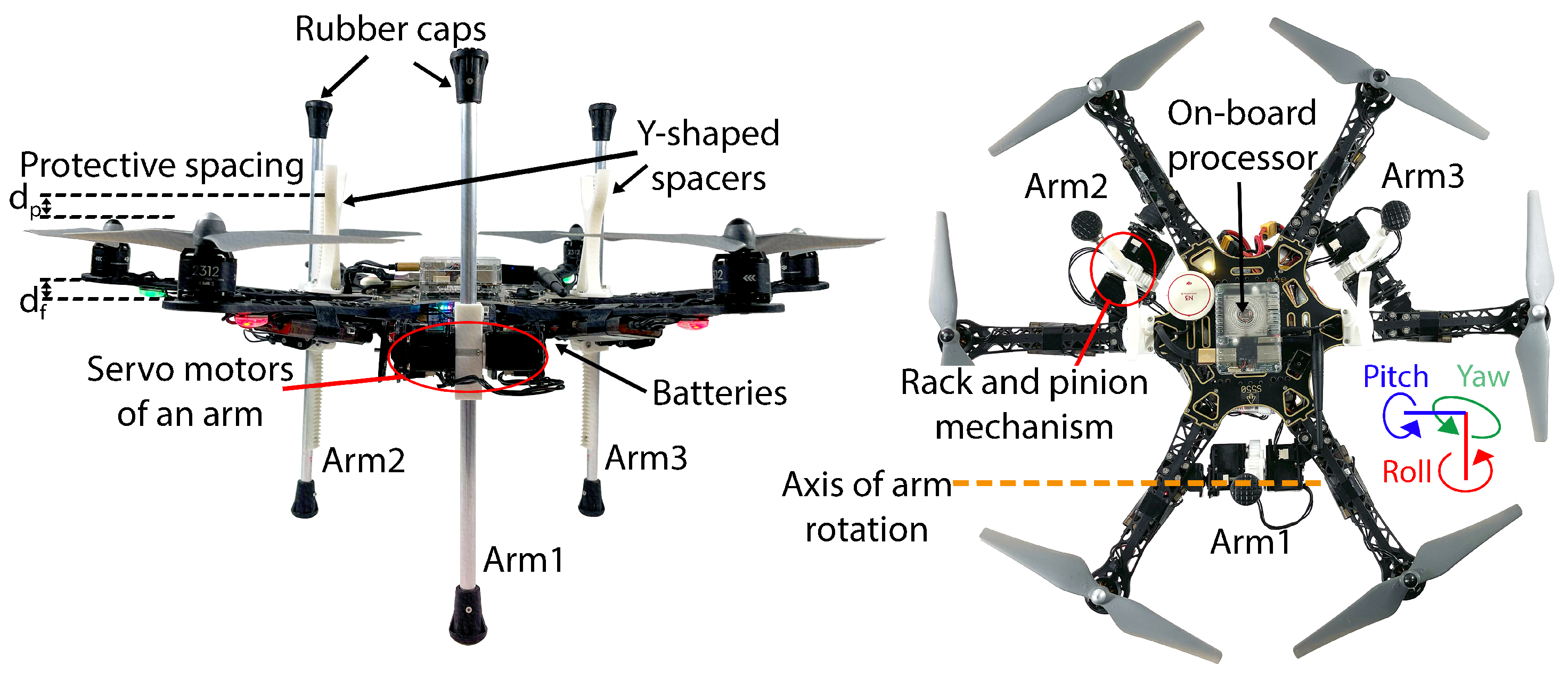
3. Hardware Description

The manipulator system proposed in this work consists of three robotic arms. The arms are made of thin aluminum pipes (10 mm), each having two degrees of freedom, i.e., revolute and prismatic joints. At its initial state, the revolute joints are located in the center of each pipe’s width so that the actuator angles and pipe angles are proportional, as shown in Figure 2 (right). The arms are attached at equal intervals around the airframe, between the rotor arms and close to the UAV’s vertical center, as shown in Figure 2 (left). The prismatic joint provides the ability to change the pivot point of the arm as well as the upper and lower ratio of the length of the arm relative to the airframe. The structure was constructed of 3D-printed PLA plastic as a rack and pinion mechanism. The reach or maximum length change of the slider depends on the length of the rack and can be modified by replacing the aluminum pipe attached to the rack. The revolute joint provides angular adjustments to an arm in all 360-degree positions in conjunction with an adjustment of the prismatic joint so that the arm tip end positions can be interchanged. Therefore, the arms can be moved from the bottom to the side and to the top. The end points of the arms are attached with rubber caps to provide higher friction contacts during manipulation tasks. The rubber caps also act as mechanical stopper and will also prevent the arm from falling off in the unlikely event of control inputs exceeding its physical limits. The joint actuation is achieved by using Robotis MX-28 servo motors. These servos are compact and, with a maximum of 2.5 N.m, provide enough torque for the tasks considered in this work. In addition to the different sensor readings, such as the feedback angle, speed control, position control, etc., they also support different modes of operation. An Odroid XU4 is used as the on-board processor, which provides motor control operations via the USB port. The manipulator system is mounted on a hexarotor airframe (S550) with a propulsion system (DJI 2312 motors) that provides a maximum thrust of about 5 kg. A DJI N3 flight controller is used for stable flight and provides communication with the on-board computer for sensor information.
The kinematics of one arm in the manipulator system is relatively straightforward, since it only has two joints. The forward kinematics is obtained by applying a translation of the prismatic joint first and then a rotation on the revolute joint. To account for the distributed positions of the arms, another rotation around the yaw axis of the UAV, depending on their location, is performed to obtain the end point positions of all three arms with respect to the airframe. The three dimensional end point position of Arm i with respect to the UAV ( i = 1 , 2 , 3 ), using forward kinematics with the revolute joint angle ( θ ) and slider displacement (l), is calculated as
x i y i z i = ( d + l sin θ ) cos ( 120 ( i 1 ) ) ( d + l sin θ ) sin ( 120 ( i 1 ) ) l cos θ
where d is the distance of manipulator attachment from the center of the UAV. The term 120 ( i 1 ) becomes 0, 120, and 240 degrees, respectively, for A r m 1 , A r m 2 , and A r m 3 , according to their arrangement on the airframe. Due to the design of the actuating joints, the arms basically has no motion control in its individual y-axes. Similarly, the inverse kinematics of an arm can be calculated by applying rotation first and then translation. The roll joint angle ( θ ) and slider displacement (l) are calculated based on three-dimensional end point of an arm as follows.
θ l = tan 1 x z x 2 + z 2
The placement of the arm and its fixture point towards the airframe allows it to rotate freely in all positions of its revolute joint if the prismatic joint is adjusted such that the arm does not hit the airframe. The arms can move freely between the rotor arms and the propellers to move over the UAV. The complete workspace generated by the motion of arms’ tips is illustrated in Figure 3a. Having a wider workspace, it is possible to realize various tasks, especially tasks involving contact with the environment. However, in this work, we only focus on landing on top of a surface and overhead docking. Therefore, the arm movement region used for each of the evaluated tasks is simplified and shown in Figure 3b for landing and Figure 3c for docking. It can be observed from the workspace region of each arm that the arm cannot move the slider at certain revolute joint angles (10 to 40 degrees position from the horizon) at the bottom of the airframe. This is because the airframe obstructs the motion of the slider at these angles.

4. Algorithms of the Focused Tasks

The manipulator mechanism is designed so that it can be used for multi-purpose tasks that are similar to our work in [11]. In this paper, we address an important task, i.e., temporarily resting, for an aerial robot with two possible solutions that can be demonstrated with the developed manipulator design. Both tasks require autonomous arms movements with the initialization commands sent by a teleoperator. The arm movements and control blocks are written in Python and integrated with ROS as shown in Figure 4 using the on-board processor. Two Li-Po batteries are used in the current prototype to power the system: one to power the on-board processor and manipulator’s actuators, and the other to power the UAV’s propulsion system and flight controller.

4.1. Adaptive Leveling

In contrast to conventional landing gears, adaptive landing gears with changing heights allow the UAV to land on an uneven surface. This type of landing is performed with physical contact to a surface from under the UAV. Therefore, the manipulators need to face downwards. Using the manipulator system developed in this work, the arms can be slid downwards for applications in this configuration. As shown in our previous works on adaptive landing using a general purpose manipulator and parallel link manipulator in [15,16], respectively, three contact points on a surface is a minimum requirement for the static stability of a UAV. However, in the previous works, we noticed that when we change the heights of each arm, the arm’s tips not only displaces vertically but also has small relative displacements in its horizontal direction. When the adaptive landing system is used to land on an uneven ground by increasing one of the arm’s height according to the terrain height in a three-dimensional region, but if the tip also changes its position in the horizontal direction, it then has to sense a different point in the terrain directly under it. This may result in the oscillating motion of the manipulator in some terrain situations. The slider joint manipulator design can allow the required movement in only the vertical direction; therefore, precise height adjustments are possible. Hence, they are more suitable compared to other types of manipulator design for adaptive landing. In addition, as described in [16], the ground may not be very stable after landing, especially when considering the landing on loose debris or ship decks. The adaptive landing system should also provide stable horizontal UAV poses even after landing on an unstable surface, for safe take-off. This process also requires the system to adjust its height. However, the friction between the manipulator’s tip and the surface will make it very hard to move if the manipulator also moves in the horizontal axis when adjusting heights.
Previously in [15], we have shown the adaptive landing process using a point cloud acquired by an on-board depth camera. In this work, as a continuation, we only show the ground stability by landing on a rocking surface to prove its ability. The IMU feedback from the flight controller is used to control and level the airframe by adjusting the manipulator’s height. The base of the three arms of the manipulator is attached to the airframe in such a way that divides the roll and pitch axes of the UAV, as illustrated in Figure 2 (right). To counter the roll change, A r m 2 and A r m 3 are adjusted in different directions, while for pitch changes, A r m 2 and A r m 3 are paired in one direction and A r m 1 in the other. A PID-based control is used to adjust the heights of the arms from its current position. The PID in the pitch axis is represented as
u p ( t ) = K p 1 e p ( t ) + K i 1 0 t e p ( t ) d t + K d 1 d d t e p ( t )
and in the roll axis as
u r ( t ) = K p 2 e r ( t ) + K i 2 0 t e r ( t ) d t + K d 2 d d t e r ( t )
where K p 1 , K i 1 , and K d 1 are the control gains used in pitch axis and K p 2 , K i 2 , and K d 2 are the control gains used in the roll axis. e p ( t ) and e r ( t ) are the pitch and roll angles of the UAV, respectively, at time t. Then, the positions of the arms are controlled by
P 1 P 2 P 3 = C 1 + u p ( t ) C 2 + u r ( t ) u p ( t ) C 3 u r ( t ) u p ( t )
Term C i is the present slider position of arm i. The plus and minus sign in each equation depends on the direction of angle change and arm placement.
The maximum height that can be displaced for an arm is equal to its length without considering the rubber cap region. Therefore, the maximum ground elevation on which the UAV can be safely landed can be estimated using the illustration in Figure 5. The maximum ground elevation θ m is related to the minimum and maximum positions of the arm and distances d 1 and d 2 , as marked in Figure 5 (right). The distances, d 1 and d 2 , depend on the roll and pitch side of the UAV in the slope as marked in Figure 5 (left). Therefore, the maximum angle, θ m , can instead be written for roll and pitch side slopes as
θ r = tan 1 ( d m a x d m i n 2 d r )
θ p = tan 1 ( d m a x d m i n d p + d a )
where d a is the distance from an arm base to UAV center. Moreover, we have the following.
d r = 3 2 d a
d p = d a 2
Therefore, θ p > θ r . According to the specification in Table 1 of the developed prototype in this work, θ p and θ r are 52.22 degrees and 48.12 degrees, respectively. In addition, slope and stairs can be considered similar for arm height adjustments. The main difference lies in the additional force component that is introduced when on slopes. However, by choosing a high-friction material for the arm tips, it is possible to withstand the sliding in slopes depending on the friction coefficient of the material.
The weight of the UAV completely rests on the manipulator system after landing. The slider’s actuator must provide enough torque to not only hold the weight but also to smoothly change it in its vertical direction. The gears of the slider mechanism are constructed with a 14 mm radius, and with the actuator torque rating used in the system, an arm can withstand 1.86 kg weight. Therefore, with three arms, the mechanism can handle weights up to 5.57 kg.

4.2. Aerial Docking

Aerial docking is commonly performed using a gripper-like structure or adhesive techniques using an embedded hardware system on a UAV [21]. Possible choices of this hardware can be on the top, bottom, or at the side of the airframe. If docking is to be performed from the side or bottom of the UAV on a horizontal pipe, making sure that the airframe is properly balanced is required so that it can stably rest there for longer periods. However, if the airframe was to be suspended from its top, as long as it is centered, it can stay there fairly stably, since the center of mass will be under the pipe. In this paper, we consider this approach of overhead docking.
Although most common approaches for overhead docking use a gripper mounted on the top or passive hook, here, we use a novel three-arm manipulator design with form closures to lock its tips after docking. The workspace for overhead docking is at the top of the airframe; therefore, the arms need to be moved to the top. After the arms of the UAV completely slide to the top, they now act as three huge fingers pointing to the top of the airframe. Since a cylindrical object can be grasped from below by contact from two of its sides, the arms are divided into a configuration with one arm on one side and two arms on the other side for docking. The arms are closed in a sequence of A r m 1 , A r m 2 , and then A r m 3 . When all tips close, the weight of the UAV locks the closed tips of the arms. The gap between the arms after closing provide form closures, as shown in Figure 6, and it will not open until sufficient torque is applied in their respective roll joints. The rubber end caps also add friction between the tips when docked. After docking, the force will be acting in the perpendicular direction of A r m 1 and A r m 2 (from closing sequence), pushing it outwards from the object, due to the downward force from the weight of the UAV. However, the third arm acts as a stopper by locking at the tips of all arms. A r m 3 also reduces the space around the object after closing to avoid airframe twists.
The analysis is carried out by considering the state of equilibrium in reference to Figure 7, where contact wrench F i and external wrench F e x t must satisfy the following equation.
F e x t = m e x t w F i = m i f i
F e x t + F i = 0
The force vector of each arm at its point of contact f i can be expressed by its magnitude f l i and components f l i ( x ) , f l i ( y ) , and f l i ( z ) .
A · f l 1 f l 2 f l 3 = 0 0 w
Matrix A is the mapping of the force magnitudes to their individual vector components by
A = 0 cos β 2 sin φ 2 cos β 3 sin φ 3 sin φ 1 sin β 2 sin φ 2 sin β 3 sin φ 3 1 / cos φ 1 1 / cos φ 2 1 / cos φ 3
φ i = ( 180 θ i )
β i refers to the angle from the x axis to the projection of the force f l i in the x y plane. Since A r m 3 is not in contact with the perching surface, the forces present in the z axis can be written as follows.
f l 1 ( z ) = f l 2 ( z ) = 1 2 w
Therefore, the magnitude of the force of each arm f l i at its point of contact can be solved via the substitution of the vertical force components of Equation (15) in Equation (12). The torque present in the revolute joint, τ i , depends on the point of contact of each individual arm. This force can then be solved by rearranging the equation below:
τ i = f l i × l c i
where l c i is the length from the revolute joint of each respective arm to the point of contact where the force is exerted. Due to the shape and material of the tips of the arms, the system is able to dock by its form closure condition. This occurs only when the tip of A r m 3 is gripped by the tips of A r m 1 and A r m 2 . The forces at the rubber cap tips, F i , of each arm are calculated by using the previously solved value of τ i as
F i = T i l p i
The length, l p i , refers to the distance from the revolute joint to the rubber cap’s tip. Hence, to achieve this condition, the force present at the tip of A r m 3 must follow
F 3 ( F 1 + F 2 ) μ k
where μ k refers to the coefficient of static friction of the rubber tips during dry contact.
The arms remain in place after docking because of the interlocked tips; hence, the power supply for the arm’s revolute joint actuator can be cut off. This type of docking using a three-arm manipulator system can be applied on any long horizontal solid objects with a diameter of less than the grasping range of the manipulator. The graspable diameter of the manipulator depends mainly on the arm’s length, their closing angle, and the spacing between them. In the system used in Figure 6 and according to Table 1, the graspable cylindrical object diameter d g is up to 60 mm.
The overhead object may also touch the propellers when docking, and a proper distance has to be maintained during autonomous flights. Two Y-shaped spacers are provided in the current design to avoid accidents due to propellers touching the object during manual navigation control. The structure allows for easy manual alignments during the docking process.

5. Experiments

Experiments were conducted to test the performance of a developed manipulator system when used for adaptive leveling and overhead docking. Experiments are categorized into the two tasks discussed in this paper. They were conducted indoors with UAV flights that were manually controlled by an intermediate level teleoperator. The arm controls were semi-autonomous, meaning that the task’s trigger command is manually sent from the remote control, and the rest of the control sequence is performed autonomously with the assistance of on-board processing. A video demonstration of the experiments is available in the Supplementary Materials.

5.1. Aerial Docking Experiment

This experiment is conducted to test the UAV’s docking on a horizontal pipe by moving the three-armed manipulator to the top of the UAV. A steel pipe of a thickness of 30 mm was fixed horizontally and high from ground by fixing it to supports on both ends and it had at least 2.5 m of its length available at the center for docking the UAV, as shown in Figure 8.
In the experiment, the UAV is teleoperated towards the pipe, and the arms are moved down to clear space above the UAV for collision-free movements. By visually looking at the pipe and adjusting the UAV’s orientation, the UAV is controlled to approach the pipe from the bottom. Once the Y-shaped spacers of the UAV touch the pipe, the docking processes’ command is initiated. The video sequence showing the docking process is shown in the form of pictures in Figure 9. The arms automatically slide up and closes in sequences, as shown in Figure 9a–e. When all arms interlock, the propellers of the UAV stop (Figure 9f). Then, the propellers start again and the take-off procedure is initiated. The arms open in a reverse sequence and slide down, as shown in Figure 9g–j. The UAV is disengaged from the pipe and controlled to move away.
To understand the experiment more clearly, the UAV’s roll, pitch, and yaw data are also shown in the form of a graph for the entire experiment’s duration in Figure 9. From the graph, we observe that, after docking, there is a very small tilt in the UAV’s roll (1 degree) and pitch (2 degrees) axes. This is because the length of the sliding arms are set to its maximum and not related to the pipe’s diameter. Since the pipe here is of 30 mm thickness, there is some gap between the closed arms and the pipe after docking. In addition, a small yaw angle change can be seen in the UAV’s resting duration because there is no upward force to maintain the orientation of the UAV during a loose grasp. However, during take-off, the closed arms and Y-shaped spacers are able to guide the UAV to straighten itself without any movements that would cause the collision of the UAV with the pipe.

5.2. Adaptive Airframe Leveling

This task is a continuation of our adaptive landing process performed with a depth camera that can sense the terrain in [15]. Assuming the UAV has already landed using that approach, in the experiment of this work, we show the UAV’s frame-leveling ability against shifting grounds. A cardboard sheet with a size greater than the airframe is set up on a small spherical base. This setup allows changing the cardboard’s slope in all of its axes. Another operator is employed to control the surface slope during the experiment. UAV and surface slope attitude can be measured independently.
The UAV is placed on the cardboard surface and the autonomous leveling control is remotely initiated. The surface slope is changed in both roll and pitch direction, up to 22 degrees range as shown in Figure 10. As observed from the graph, the manipulator system counters this motion by sliding the arms to always keep the airframe horizontal. With the autonomous leveling control active, the airframe was able to maintain its posture within 4 degrees from the horizontal reference. To show the UAV’s safe take off from a sloped surface, it is teleoperated to take off at the end of the experiment. The surface slope is observed to be 15 degrees at this point.

6. Discussion and Future Works

In adaptive leveling experiments, we observed that the airframe’s slope deviates when the surface slope changes rapidly and dynamically adjusts the UAV’s frame towards a horizontal position that is fit for take-off operations and to prevent being tipped over. Although the current control system is enough to land on a dynamic surface, the control system can be improved by adding force sensors on the arm’s tips along the UAV’s IMU feedback for substantially smoother and faster leveling.
In the docking experiment, a gap between the closed arms and the object is seen, which moves the airframe slightly after docking. This gap can be reduced by sliding the arms down to make a tighter grasp after docking on it. The slider actuator’s position feedback can be used in future to sense and stop the slider to form a tighter grasp. The interlocking tips of the arms allows for three-armed docking without requiring torque on the revolute joints to hold the angles after closing.
In addition to straight pole, it is also able to dock on unevenly shaped objects such as tree branches, as shown in Figure 11. However, the branch should be thin enough and the shape should fit within the closed configuration of the arms used for docking. Furthermore, it is also possible to adaptively level the airframe after docking by sliding the arms to control the airframe’s attitude given that the arms are long enough to provide the required sliding lengths.
The experiments show the realization of two tasks using the developed prototype with manual UAV teleoperation. Horizontal cylindrical object detection for docking and ground elevation detection for landing using a vision system along with autonomous UAV position control are considered in future work.

7. Conclusions

The task-specific constraint of aerial manipulators for UAVs can be solved by designing a multi-purpose aerial manipulator system capable of performing more critical and advanced functions. In this work, a lightweight aerial manipulator system with three arms is developed. The arms are designed to work in prismatic and revolute joint configurations to easily set their heights and angles. The realization of two advanced tasks for a UAV to level itself for safe take-off and to dock on cylindrical objects using the developed system is demonstrated.
When deployed to a remote area, a UAV may need to suspend its flight for a variety of reasons. We expand on our previous three-arm aerial manipulator system of adaptive landing with terrain depth sensing presented in [15] and show the implementation of autonomously leveling the airframe on a dynamically unstable surface after landing for a safe vertical take-off operation. In addition, we show the successful execution of overhead docking using the three arms of the system. This overhead docking ability can be used to land the UAV on suitable and nearby elevated structures, especially when there is no proper landing surface available at ground level.
Two distinct methods for suspending a UAV’s flight using various configurations of an on-board manipulator system were demonstrated. By making the aerial manipulators more versatile, the UAV will be able to handle unforeseen circumstances when deployed remotely in an unfamiliar environment.

Supplementary Materials

The following are available at https://www.mdpi.com/article/10.3390/drones6120380/s1—Video S1.

Author Contributions

The contributions of the authors are as follows: H.P. developed the concept, prototype, and controllers; performed experiments; analyzed the results; and wrote the manuscript. R.R.M. analyzed the design, performed experiments, and wrote the manuscript. R.L. provided design advice, validated results, and wrote the manuscript. K.S. provided design advice, supervised, validated results, and wrote the manuscript. All authors have read and agreed to the published version of the manuscript.

Funding

This work was partially supported by JST, CREST Grant Number JPMJCR22C1, Japan.

Institutional Review Board Statement

Not applicable.

Informed Consent Statement

Not applicable.

Data Availability Statement

Not applicable.

Conflicts of Interest

The authors declare no conflict of interest.

References

  1. Ollero, A.; Tognon, M.; Suarez, A.; Lee, D.; Franchi, A. Past, present, and future of aerial robotic manipulators. IEEE Trans. Robot. 2021, 38, 626–645. [Google Scholar] [CrossRef]
  2. Ruggiero, F.; Lippiello, V.; Ollero, A. Aerial manipulation: A literature review. IEEE Robot. Autom. Lett. 2018, 3, 1957–1964. [Google Scholar] [CrossRef] [Green Version]
  3. Ladig, R.; Paul, H.; Miyazaki, R.; Shimonomura, K. Aerial manipulation using multirotor UAV: A review from the aspect of operating space and force. J. Robot. Mechatron. 2021, 33, 196–204. [Google Scholar] [CrossRef]
  4. Jimenez-Cano, A.; Braga, J.; Heredia, G.; Ollero, A. Aerial manipulator for structure inspection by contact from the underside. In Proceedings of the 2015 IEEE/RSJ international conference on intelligent robots and systems (IROS), Hamburg, Germany, 28 September–3 October 2015; pp. 1879–1884. [Google Scholar]
  5. Suarez, A.; Caballero, A.; Garofano, A.; Sanchez-Cuevas, P.J.; Heredia, G.; Ollero, A. Aerial manipulator with rolling base for inspection of pipe arrays. IEEE Access 2020, 8, 162516–162532. [Google Scholar] [CrossRef]
  6. Bartelds, T.; Capra, A.; Hamaza, S.; Stramigioli, S.; Fumagalli, M. Compliant aerial manipulators: Toward a new generation of aerial robotic workers. IEEE Robot. Autom. Lett. 2016, 1, 477–483. [Google Scholar] [CrossRef] [Green Version]
  7. Kristensen, A.S.; Ahsan, D.; Mehmood, S.; Ahmed, S. Rescue Emergency Drone for fast response to medical emergencies due to traffic accidents. Int. J. Health Med. Eng. 2017, 11, 637–641. [Google Scholar]
  8. Van de Voorde, P.; Gautama, S.; Momont, A.; Ionescu, C.M.; De Paepe, P.; Fraeyman, N. The drone ambulance [A-UAS]: Golden bullet or just a blank? Resuscitation 2017, 116, 46–48. [Google Scholar] [CrossRef] [PubMed]
  9. Kim, S.; Seo, H.; Kim, H.J. Operating an unknown drawer using an aerial manipulator. In Proceedings of the 2015 IEEE International Conference on Robotics and Automation (ICRA), Seattle, WA, USA, 26–30 May 2015; pp. 5503–5508. [Google Scholar]
  10. Suarez, A.; Jimenez-Cano, A.; Vega, V.; Heredia, G.; Rodriguez-Castaño, A.; Ollero, A. Lightweight and human-size dual arm aerial manipulator. In Proceedings of the 2017 international conference on unmanned aircraft systems (ICUAS), Miami, FL, USA, 13–16 June 2017; pp. 1778–1784. [Google Scholar]
  11. Paul, H.; Miyazaki, R.; Ladig, R.; Shimonomura, K. TAMS: Development of a multipurpose three-arm aerial manipulator system. Adv. Robot. 2021, 35, 31–47. [Google Scholar] [CrossRef]
  12. Paul, H.; Ono, K.; Ladig, R.; Shimonomura, K. A multirotor platform employing a three-axis vertical articulated robotic arm for aerial manipulation tasks. In Proceedings of the 2018 IEEE/ASME International Conference on Advanced Intelligent Mechatronics (AIM), Auckland, New Zealand, 9–12 July 2018; pp. 478–485. [Google Scholar]
  13. Lee, D.; Ryan, T.; Kim, H.J. Autonomous landing of a VTOL UAV on a moving platform using image-based visual servoing. In Proceedings of the 2012 IEEE International Conference on Robotics and Automation, St. Paul, MN, USA, 14–18 May 2012; pp. 971–976. [Google Scholar]
  14. Sarkisov, Y.S.; Yashin, G.A.; Tsykunov, E.V.; Tsetserukou, D. Dronegear: A novel robotic landing gear with embedded optical torque sensors for safe multicopter landing on an uneven surface. IEEE Robot. Autom. Lett. 2018, 3, 1912–1917. [Google Scholar] [CrossRef]
  15. Paul, H.; Miyazaki, R.; Ladig, R.; Shimonomura, K. Landing of a multirotor aerial vehicle on an uneven surface using multiple on-board manipulators. In Proceedings of the 2019 IEEE/RSJ International Conference on Intelligent Robots and Systems (IROS), Macau, China, 3–8 November 2019; pp. 1926–1933. [Google Scholar]
  16. Paul, H.; Miyazaki, R.; Kominami, T.; Ladig, R.; Shimonomura, K. A Versatile Aerial Manipulator Design and Realization of UAV Take-Off from a Rocking Unstable Surface. Appl. Sci. 2021, 11, 9157. [Google Scholar] [CrossRef]
  17. Thomas, J.; Loianno, G.; Daniilidis, K.; Kumar, V. Visual servoing of quadrotors for perching by hanging from cylindrical objects. IEEE Robot. Autom. Lett. 2015, 1, 57–64. [Google Scholar] [CrossRef]
  18. Kitchen, R.; Bierwolf, N.; Harbertson, S.; Platt, B.; Owen, D.; Griessmann, K.; Minor, M.A. Design and evaluation of a perching hexacopter drone for energy harvesting from power lines. In Proceedings of the 2020 IEEE/RSJ International Conference on Intelligent Robots and Systems (IROS), Las Vegas, NV, USA, 25–29 October 2020; pp. 1192–1198. [Google Scholar]
  19. Popek, K.M.; Johannes, M.S.; Wolfe, K.C.; Hegeman, R.A.; Hatch, J.M.; Moore, J.L.; Katyal, K.D.; Yeh, B.Y.; Bamberger, R.J. Autonomous grasping robotic aerial system for perching (agrasp). In Proceedings of the 2018 IEEE/RSJ International Conference on Intelligent Robots and Systems (IROS), Madrid, Spain, 1–5 October 2018; pp. 1–9. [Google Scholar]
  20. Hang, K.; Lyu, X.; Song, H.; Stork, J.A.; Dollar, A.M.; Kragic, D.; Zhang, F. Perching and resting—A paradigm for UAV maneuvering with modularized landing gears. Sci. Robot. 2019, 4, eaau6637. [Google Scholar] [CrossRef] [PubMed]
  21. Wopereis, H.W.; Van Der Molen, T.; Post, T.; Stramigioli, S.; Fumagalli, M. Mechanism for perching on smooth surfaces using aerial impacts. In Proceedings of the 2016 IEEE international symposium on safety, security, and rescue robotics (SSRR), Lausanne, Switzerland, 23–27 October 2016; pp. 154–159. [Google Scholar]
Figure 1. Illustrations of the concepts of adaptive airframe leveling (left) and aerial docking (right) using the proposed manipulator system.
Drones 06 00380 g001
Figure 2. Front view (left) and top view (right) of the developed aerial robot with a three-arm manipulator system.
Drones 06 00380 g002
Figure 3. (a) Total workspace of the three arms. (b) Movement during adaptive leveling. (c) Movement during overhead docking.
Drones 06 00380 g003
Figure 4. Block diagram of the proposed system.
Drones 06 00380 g004
Figure 5. Relative arm mount distances and estimating the maximum landable terrain slope.
Drones 06 00380 g005
Figure 6. Illustration of the side-view (left) and top-view (right) of the manipulator system during docking with an object.
Drones 06 00380 g006
Figure 7. Free body diagram of the contact forces present during docking.
Drones 06 00380 g007
Figure 8. Docking experiment setup.
Drones 06 00380 g008
Figure 9. Docking experiment on a steel pipe with a clear view of the manipulator’s movements. Docking process (ae). UAV resting with propellers switched off (f). Take-off process (gj).
Drones 06 00380 g009
Figure 10. Adaptive leveling experiment against changing surface elevations. Leveling control is active (af). UAV take off (g,h).
Drones 06 00380 g010
Figure 11. Docking on a non-straight tree branch.
Drones 06 00380 g011
Table 1. Specifications of the system’s components.
ComponentSpecificationValue
One armMaterialAluminum and PLA
Width × height10 mm × 370 mm
Slider displacement60 mm (min), 350 mm (max)
Weight0.28 kg
AirframeRotors6
Weight1.2 kg
Entire robotArms3
Width × height (min)590 mm × 310 mm
Weight including 2 batteries3.0 kg
Publisher’s Note: MDPI stays neutral with regard to jurisdictional claims in published maps and institutional affiliations.

