1. Introduction
Unmanned Aerial Vehicles (UAVs) refer to a wide range of devices, ranging from lightweight multicopter to autonomous fixed-wing aircraft of several tons. By far the largest number of UAVs are used for recreational non-commercial purposes. They are operated at altitudes below 500 ft, also known as Very Low-Level Airspace (VLL) and share this altitude band with other manned airspace users, such as general aviation (e.g., emergency procedures training), Helicopter Emergency Medical Services (HEMS) as well as police and military aircraft ([
1] p. 5). Busy airspaces (e.g., around airports) are usually set up as controlled airspace (Class D CTR), where Air Traffic Control (ATC) regulates entry and exit and coordinates aircraft movements. UAVs are typically prohibited from entering or ascending in these airspaces. In recent years, small unmanned platforms in the range of up to 25 kg have also been used within controlled airspaces as a cost-effective alternative for routine maintenance work. This includes inspecting the runway for damage [
2], scaring away birds [
3], improving weather conditions [
4] or calibrating radio navigation aids, such as the Instrument Landing System [
5].
High visibility and a reliable communication link are essential for safe operations inside and around airports. In addition to the minimum equipment, that consists of a two-way radio and a Secondary Surveillance Radar (SSR) transponder supporting Mode A/C or Mode S [
6], “see and avoid” is one of the most important principles for safe flights under Visual Flight Rules (VFR). However, due to the relatively small diameter of the unmanned aircraft, maintaining visual contact is difficult if not impossible, especially for arriving and departing traffic [
7,
8,
9]. An analysis of the potential hazards of UAVs for runway inspections ([
10] p. 284) revealed the following recommendations, among others, to minimize risks of collisions:
Control and limit the entry of other UAVs to ensure safe operation within the control zone
Equip UAVs with a transponder to be visible on radar to the ATC as well to other air traffic participants
Equip UAVs with collision warning systems
Today’s commercially available Unmanned Aircraft Systems (UASs) in the range of up to 25 kg are usually equipped with geofencing technology to prevent unintentional entries into sensitive airspace. However, this mechanism does not contribute to the visibility or connectivity of the UAV for intended use within controlled airspace.
Apart from radio-based traffic reports from flight information services, turbine powered aeroplanes with a maximum certificated take-off mass over 5700 kg or more than 19 passengers are equipped with the Airborne Collision Avoidance System II [
11], whereas aircraft from the general aviation domain typically rely on Automatic Dependent Surveillance Broadcast (ADS-B) data for situational awareness, presuming the presence of a suitable transponder. By broadcasting precise position information to surrounding traffic on a permanent basis, evasive maneuvers can be coordinated in the event of dangerous approaches. Like other surveillance systems [
12], both technologies share the spectrum at 1030 and 1090 MHz for this purpose. With 400,000 forecasted drones by 2050 ([
13] p. 4) this part of the spectrum becomes a limited resource [
14]. Furthermore, certified hardware is often heavy, bulky and costly and therefore less suitable for the integration into small UAVs.
Hence, different approaches have been proposed to imitate the functionalities of ADS-B with the help of alternative, more lightweight point-to-point communication technologies like Automatic Packet Reporting System (APRS) [
15], Bluetooth, LoRa or Wi-Fi [
16]. Another promising approach is cellular networks. They provide high capacity and bandwidth, large coverage, low latency, reliability, inherent navigation, availability and beyond line-of-sight operation. For instance, the Fifth Generation Mobile Networks (5G) supports data rates of up to 10 Gbits/s and provides latencies of about 1 ms [
17]. However, there are some challenges that need to be carefully investigated in the design process, like coexistence with ground mobile users, handovers and the tilt of base stations. To solve these problems, UAVs are an essential part in the standardization of 5G for the safe operation of UAS, and there has been a lot of activities in the 3rd generation partnership project (3GPP) to ensure reliable 5G New Radio (NR) connectivity for drones, e.g., Release 15 and Release 17 [
18].
Unlike in manned aviation, there is no established UAS Traffic Management (UTM) system in Europe yet. The literature contains different approaches for the safe and efficient integration of UAS into national airspaces [
19,
20,
21,
22]. Within the framework of the SESAR Joint Undertaking, the EU is pursuing the concept of U-Space [
23], which proposes several services that should lead to automated, inter-operable and sustainable UTM solutions. In this context, the research and development of the different services is distributed in four successive phases U1-U4, with each development phase increasing the level of autonomy and connectivity of the UAS. According to the current state of research report, most of the previous work focused on the services of phases U1 and U2, whereas few services of U3 and none of U4 have been studied [
24] by now. Among the least studied services were collaborative interface with ATC (7%) and tactical conflict resolution (3%). The literature also points out that end-to-end latency (UAV-to-UAV) is a critical metric in the UTM context, however, data from real life experiments is still missing ([
16] p. 94).
From the work done so far, cellular networks will represent an essential component in future UTM systems. At the same time, it must be assumed that the transponder method in combination with ADS-B will be the primary technology for collision avoidance in manned aviation for the near future. In the following, this article introduces a Multi-Mode-Transceiver (MMT) that combines current Mode S transponder technology including ADS-B In/Out with a cellular interface to enhance UAS visibility and connectivity in mixed Air Traffic Management (ATM) and UTM environments. Embedded in a prototypical UTM system, the capabilities of the MMT as well as a novel collaborative interface to ATC are tested under real life conditions. The selected use case represents a UAV transit through a controlled airspace with simulated and real traffic. Furthermore, this work provides the following contributions:
Experimental implementation of a cooperative UTM system based on a cellular Long Term Evolution (LTE) network utilizing the Message Queuing Telemetry Transport (MQTT) protocol [
25]
Measurements of message trip times in the UTM network under real life conditions
Evaluation of a collaborative interface with ATC using the MMT
Evaluation of a power-reserve-based tactical collision avoidance method utilizing cooperative traffic information data
2. Materials and Methods
UAS as traffic participants in controlled airspace are currently the exception rather than the rule. As a result, operating procedures in such dense airspace are not yet standardised and unmanned flights must therefore be approved in advance. The automation of this process is slowed down, among other things, by the fact that flight clearances are primarily transmitted via voice-based communication. Given the predicted increase in the number of UAVs movements in the coming decades, this type of communication may soon reach its limits, so that an alternative digital data link between ATC and UAS will be required. New communication interfaces will also be needed for future UTM systems.
2.1. Multi-Mode-Transceiver
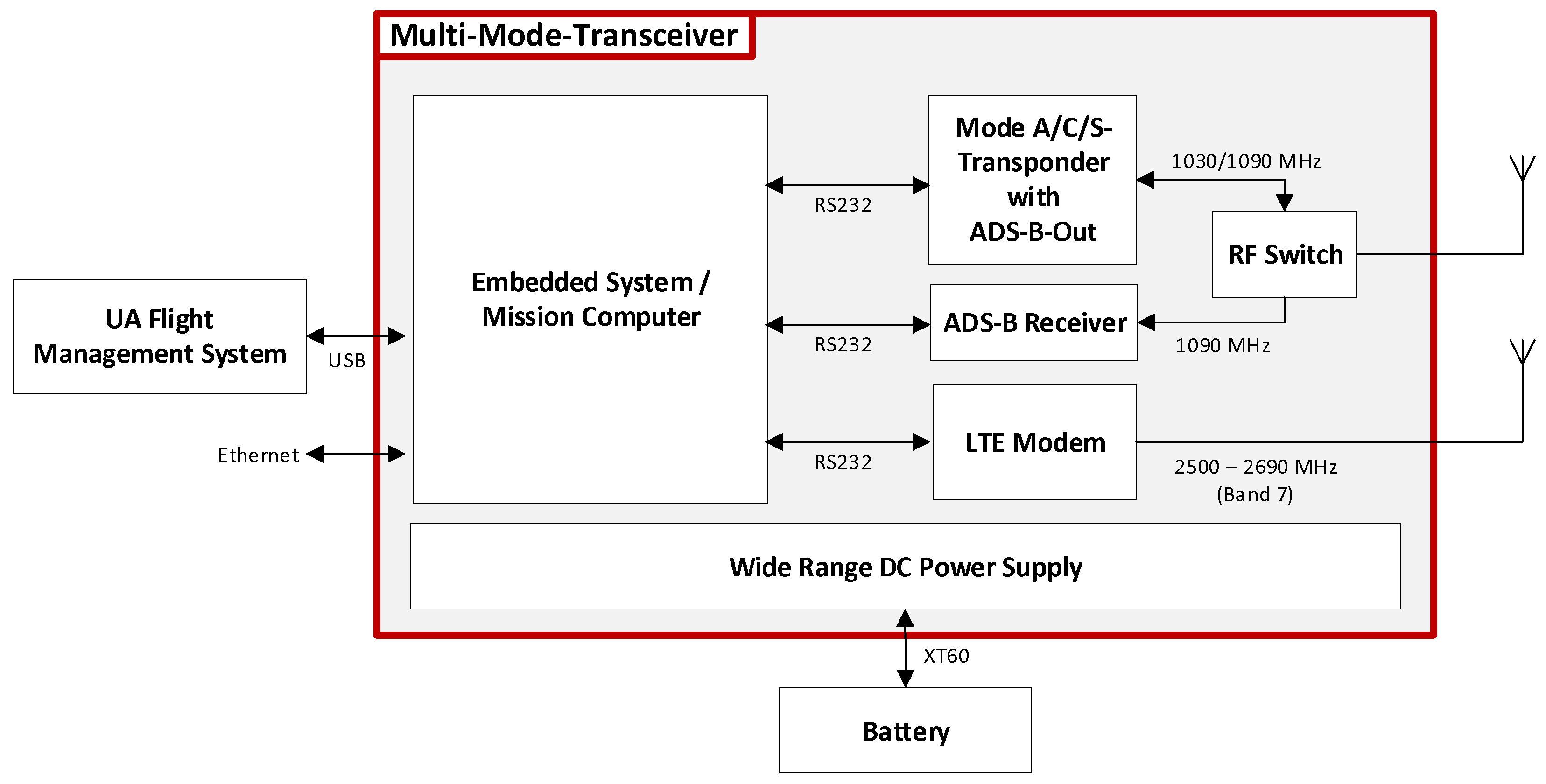
In cooperation with a German avionics manufacturer [
26] an EASA/FAA certified Mode A/C/S transponder including ADS-B In/Out capability was extended by a miniaturised embedded system [
27] and a mobile radio interface [
28]. The board serves as a control center between the individual components of the MMT and also provides the computing power required for operation as a mission computer. Depending on the current flight phase, individual communication channels can be switched on and off in order to meet the requirements of the respective airspace. For the internal communication between the components, serial interfaces (RS232) were used. Additional external interfaces (USB, Ethernet) were added for external communication, e.g., with the Flight Management System
(FMS) of the UAV. To support variable input voltage, the integrated power supply was modified, enabling the MMT to be operated with a standard 4S lithium polymer accumulator (14.8 V to 16.8 V).
Figure 1 gives an overview of the MMT components and their interconnections.
2.2. MMT Integration
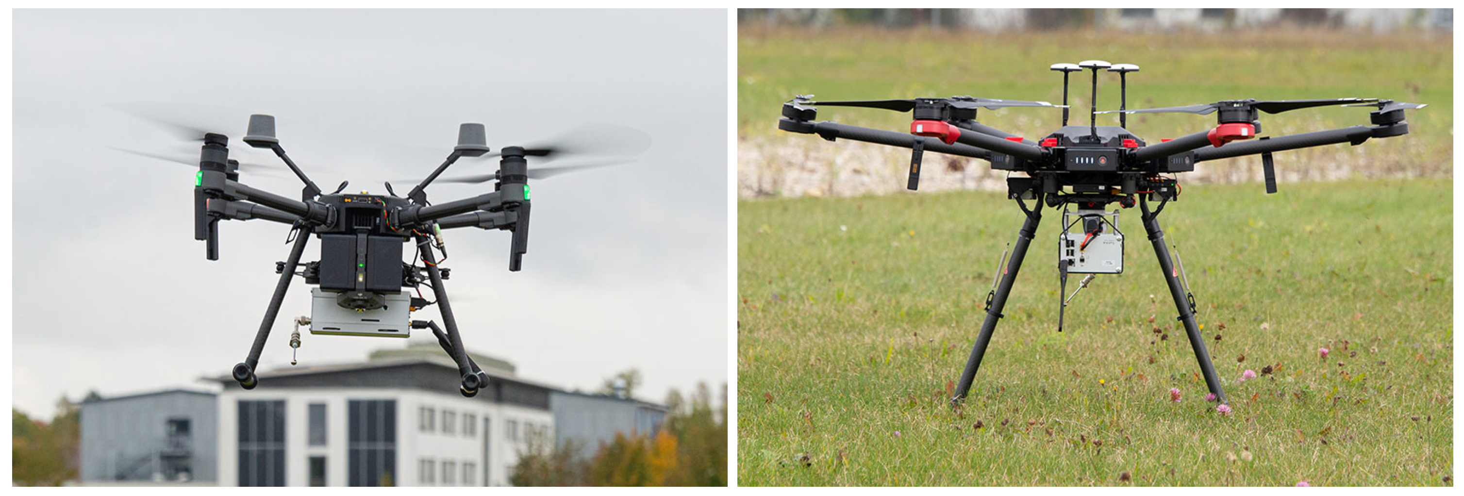
Based on the dimensions (160 × 70 × 120 mm) and the weight (1024 g) of the MMT prototype, two small commercial UAS with maximum take-off weights (MTOW) of
kg (DJI Matrice 210 RTK v2,
Figure 2 left) and
kg (DJI Matrice 600 Pro,
Figure 2 right) were selected for integration and each equipped with a device. Although both UAVs provide power for the payload, a separate power supply was used by means of a 4S lithium polymer accumulator with a capacity of 1300 mAh, mounted between the aircraft and the MMT to avoid interference with the FMS due to unforeseen voltage spikes. For communication with the FMS, the MMT was connected directly to the UAV via a USB interface.
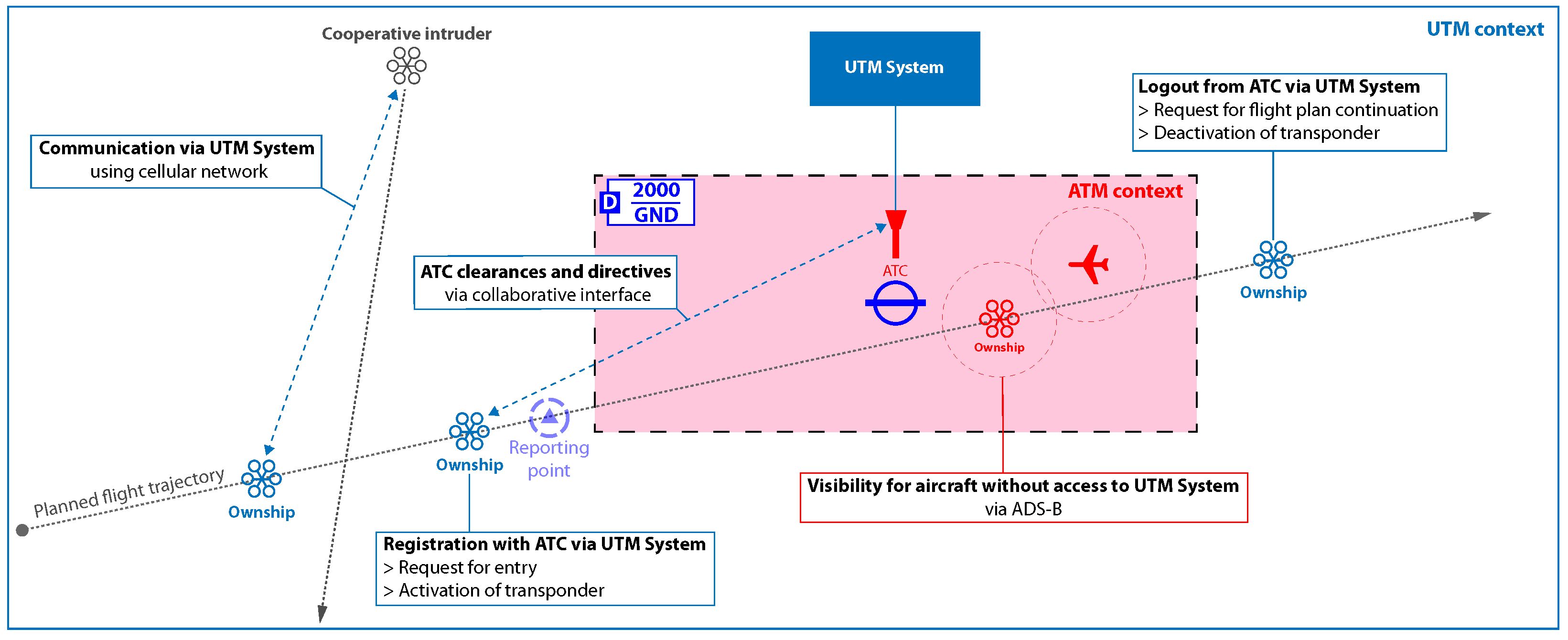
2.3. Operational Use Case
A fully automated inspection flight along a pre-planned route passing through controlled airspace was defined as the test scenario (
Figure 3). During the mission, the UAV is always connected to a UTM system and avoids cooperative traffic independently. Before entering the controlled airspace, the UAV contacts ATC to obtain clearance. While flying within controlled airspace, the UAV autonomously activates the Mode S transponder to be visible via ADS-B to manned traffic. All flight movements of the UAV within the control zone are coordinated with ATC via a collaborative interface. After leaving the controlled airspace, the UAV autonomously deactivates the transponder, as manned traffic is not to be expected at VLL airspace outside of a CTR. This way, the footprint on the 1030 MHz/ 1090 MHz spectrum can be minimized. During the complete flight, the telemetry and system states are monitored via the UTM system by the operator.
2.4. Experimental UTM Environment
The radio interface of the MMT enables the UAS to connect to a UTM system via cellular mobile networks. The European ATM Master Plan [
29] describes future U-space services in Annex 1, which are to be used in different expansion stages (U1–U4). Since no established UTM system was available at the time of the work, a prototypical UTM system was developed and implemented to evaluate the MMT in a mixed ATM/UTM context. This system includes a server that provides the following UTM services with basic functionality.
E-Registration (U1). This service offers the UAS operator the possibility to register himself as well as one or more UAS in the UTM network. Each operator and each UAS is assigned a unique identification number.
Pre-tactical Geofencing (U1). The UAS operator is provided with information on airspaces with special flight restrictions (e.g., control zones). The provision of daily updated aeronautical information (e.g., NOTAMs) is not part of the UTM system in this context.
Flight planning management (U2). Based on the requested flight route and possible airspace restrictions, the UTM server receives flight plans and grants or denies them. In case of approval, a unique flight number is generated and transmitted to the UAS operator.
Tracking (U2). The UTM server receives position reports from UAVs and merges them into an up-to-date air picture.
Traffic Information (U2). On request, the UTM server periodically provides a list of other aircraft located in the immediate vicinity of the UAV.
Procedural Interface with ATC (U2). This service ensures the flow of information between the UTM server and an ATC for those cases where a flight through its control zone is intended. In this case, the decision to approve the flight plan is made with the appropriate ATC.
Collaborative Interface with ATC (U3). ATC has the option of contacting the UAS via the UTM system and transmitting instructions (to leave the control zone, land the aircraft, etc.) in order to be able to act promptly in special situations. These are forwarded to the UAV as well as to the Ground Control Station (GCS) of the operator.
Communication protocol. At the application level, messages are transmitted via the MQTT protocol version 3.1.1 [
25]. MQTT is an established open message protocol for the transmission of telemetry data between different systems in restricted networks, e.g., in the Internet-of-Things (IoT) context, and follows the rules of indirect publish-subscribe communication. Clients can publish messages on topics (e.g.,
utm/uav123/position) within the network or subscribe to specific topics to receive relevant messages. A broker takes over the message management and distribution to the corresponding clients, so that no direct communication exists between them. The protocol also supports multiple Quality of Service (QoS) policies for the reliability of message transmissions:
At most once (QoS 0): reception of the message is not guaranteed, similar to UDP
At least once (QoS 1): receiver confirms receipt of message, multiple receipt of the same message possible
Exactly once (QoS 2): message is guaranteed to arrive at the receiver only once
In addition, the protocol offers other useful functions for data transmission in an unreliable network. When establishing a connection with the MQTT broker, a client can place a message as a “last will and testament”. In the event of a connection failure, this message is delivered to all clients that have subscribed to this topic. The formatting of the messages is based on the recommendation of GUTMA [
30], encoded in the JavaScript Object Notation (JSON) file format [
31] with the UTF-8 character set. Flight restriction areas are mapped in geoJSON data format [
32]. In order to be able to record data packets transported via the UTM network, a MQTT2ROS bridge [
33] was integrated that subscribes to all available topics. This bridge converts MQTT messages into Robot Operating System (ROS) compatible messages and forwards them into a local ROS environment [
34] so that they can be saved in a so-called BAG-file for further analysis and replay.
Figure 4 depicts the implemented topics with the respective publishers and subscribers.
Reference Applications. In order to simulate the interactions of the UTM participants, so-called reference applications were developed and implemented. This includes the ServerApp, which represents the core component of the UTM network and is responsible for processing flight declarations and position reports. The ATCApp (
Figure 5) represents the collaborative interface of the Air Navigation Service Provider (ANSP) to the UTM network and enables the air traffic controller to communicate with the UAS without a voice radio link. On the UAV’s mission computer, the OnboardApp provides access to the UTM network and a UserApp allows the UAS operator to file flight plans, make system changes onboard the UAV and monitor the flight progress.
2.5. Mobile Network Infrastructure
To test new UTM concepts and use cases with UAS in a real environment, an own 4G/5G testbed was set up at the facilities in Neubiberg, Germany. The testbed is based on 3rd Generation Partnership Program (3GPP) Release 15 and enables a much more flexible test environment due to the free selection of equipment and network parameters compared to commercial mobile networks.
The discussion starts with a brief summary of the main features of each 4G/5G network component, as they are essential for understanding the proposed 4G/5G concept. The setup for the evaluation testbed supports the so-called NR Non-Standalone Access (NSA) which is currently used by most mobile operators for their initial NR roll out [
35].
2.5.1. 4G/5G Core Network
The Evolved Packet Core (EPC) consists of the most common components for the user authentication, the central database for all subscriber-related data and the routing to other networks. In addition, it supports mobility management as well as call and session building:
Packet Data Network Gateway (PGW)
Serving Gateway (SGW)
Mobility Management Entity (MME)
Home Subscriber Server (HSS)
2.5.2. Radio Access Network
LTE Base Station (4G): Evolved Node B
The LTE base station Evolved Node B (eNB) provides all radio access functions via the air interface. The eNB manages the radio resources (Radio Resource Control (RRC), dynamic scheduling), takes care of the routing of user data to the SGW and operates the transmission of paging and broadcast messages via the air interface. Internet Protocol (IP) header compression and the encryption of user data are also functions that are covered by the base station. In addition, measurement reports on the channel quality are created. Furthermore, the eNB is responsible for selecting an MME for the User Equipment (UE) attachment, which is not specified by the terminal itself.
NR Base Station (5G): Next Generation Node B
The Next Generation Node B (gNB) performs essentially identical functions as the eNB. However, it also offers new functionalities on the air interface such as Beamforming which increase data rates compared to the eNB. According to the standard, besides the Frequency Range 1 (FR1) below 6 GHz, the so-called millimeter waves above 20 GHz in the Frequency Range 2 (FR2) are also used. Due to the much larger bandwidth in FR2, higher data rates are possible compared to FR1.
2.5.3. VPN Solution
Virtual Private Network (VPN) tunneling protocols are used for the secure forwarding of IP-Packets between physically distant networks. Well-known examples of such protocols are OpenVPN and IPsec, both of which are equipped with security features that ensure the confidentiality, integrity and authenticity of the forwarded packets. WireGuard is a modern alternative to OpenVPN and IPsec. Compared to these, WireGuard offers higher performance, better usability and stronger security.
2.6. Mobile Network Implementation
A small cell solution based on the 4G/5G protocol stack from Amarisoft was selected for the mobile network. The small cell is a radio front-end based on a Software Defined Radio (SDR), which operats with a powerful consumer computer. On this computer, the actual base station software (eNB/gNB) and the 4G/5G core network can be operated together. The base station is able to generate the radio signal in various standardized 4G/5G Frequency Ranges (FRs). The network architecture including the Core Network (CN) and the Internet gateway is shown in
Figure 6.
For outdoor LTE testing, active high-frequency components and antennas are necessary to ensure sufficient signal strength at the receiver. The utilized logarithmic-periodic antenna has an antenna gain of dBi. The antenna diagram is directional and can be operated in the FR 790 MHz to 2700 MHz. The antennas were mounted on a 2 m mobile mast with a tilt of 10° to allow a better coverage for the UAVs. Transmit and receive antennas were mounted two meters apart and used different polarization to avoid interference from the transmit to the receive path. For the FR 2300 MHz to 2700 MHz, amplifier Kuhne Electronic KU PA 230270-18 is used. The output power of the amplifier at the 3 dB compression point is 44 dBm. In operation, the amplifier can be operated with a maximum input power of 7 dBm. To amplify the reception signal of the base station, a low-noise amplifier is required. The amplifier Kuhne electronic KU LNA BB 2227 with a gain of 25 dB was selected which operates in FR 2200 MHz to 2700 MHz.
The LTE cell was operated in Frequency Division Duplex (FDD) mode. FDD enables Uplink (UL) and Downlink (DL) transmission at the same time, but over different frequency bands to avoid interference. Most LTE cells in rural areas of commercial operators in Germany are using this mode as well. For the DL from the LTE base station to the terminals, 5 MHz wide carriers were used. The UL from the terminals to the LTE base station was also in a 5 MHz wide carrier. The spacing of the LTE subcarriers is 15 kHz. This results in a raw symbol rate of
Msps for a system with 5 MHz bandwidth. The maximum data rate that can be achieved depends on the Signal-to-Noise Ratio (SNR) at the receiver and the resulting modulation of the signal at the transmitter. The exact LTE Modulation and Coding (MODCOD) format is thus selected depending on the prevailing conditions. LTE band 7 was used for the transmission itself. The equivalent isotropic radiated power in the DL was approximately 50 dBm. In addition, three Commercial Off-The-Shelf (COTS) UEs were utilized to connect the UTM-server and the GCS computers as shown in
Figure 7. The two MMTs provide the air-to-ground LTE link for the UAVs. Each MMT is equipped with an omnidirectional 4 dBi antenna. An additional Internet gateway for the non-public network was enabled via a COTS LTE router with a SIM card.
Since the NR cell operates in a different FR, different antennas and amplifiers are required for the NR scenario compared to LTE in band 7. Hence, a NSA mobile network is needed, in which the LTE and NR cells can be operated in parallel in different FRs. The main components for the GHz FR are listed below:
Kathrein 80010922 sector antenna with 17 dBi gain
LNA mini circuits ZX60-83LN12+ with 20 dB gain
MPA mini circuits ZHL-4240+ with 40 dB gain
For the demonstration of the NR cell, the Huawei CPE NR Pro Router was integrated, one of the early NR devices since 2020. The Testbed allows NR access utilizing a 40 MHz Time Division Duplex (TDD) carrier in the FR 3700 MHz to 3800 MHz band for non-public networks in Germany. However, the focus of the evaluation is on LTE because this technology is more widespread in rural areas and is still preferred by network operators for cost reasons.
2.7. Evaluation Concept
The flight tests were carried out on the test site of the University of the Bundeswehr Munich and divided into five experiments (V1–V5). V1 covered the basic system functions of the MMT and UTM, whereas V2 contained the transmission and approval of flight plans as well as the monitoring during the flight using the UTM network. The focus of V3 was on the collaborative interface with ATC regarding the compliance with entry/exit rules, the remote switching of the transponder modes and codes as well as ATC initiated emergency landing procedures. For that purpose a virtual controlled airspace (100 × 50 × 25 m) with four reporting points was integrated into the UTM network. Experiments V4 and V5 focused on the collision avoidance for cooperative intruder based on telemetry data from the UTM network as well as from ADS-B.
For this purpose, a simple Detect-and-Avoid (D&A) approach was implemented. In addition to the current position and the next waypoints, each UAS transmits the status of its own energy supply (state of charge (SoC) in percent). The D&A subsystem analyzes the received traffic information every 0.5 s. In the event of a shortfall of the horizontal or vertical minimum distance to the nearest flying traffic, a decision is made on the basis of the remaining energy reserve. The aircraft with higher SoC must pause the flight (transition into hovering), whereas the other may continue its flight. Safety distances were defined to be 50 m horizontally and 100 ft vertically for a maximum horizontal airspeed of 5 m/s. This intruder scenario was first tested with a real ownship and a simulated intruder (V4), followed by a real intruder (V5). A detailed list of the investigated parameters in the respective experiments is shown in
Figure 8. During the evaluation, a wide variety of data was recorded on the individual system components (
Figure 9). These included:
Signal strengths at LTE base station
All inbound and outbound traffic at the UTM server
ADS-B In data at a stationary ADS-B receiver
Screen recordings of user interfaces
Video recordings of UAV’s flight movements
4. Discussion
4.1. Simultaneous Operation of Mobile Radio and Transponder
In flight operations, there was strong interference in the LTE module after the transponder was activated, and as a consequence, the connection to the UTM network was interrupted. A reduction of the transponder transmission power from the standard setting of up to 200 W to about 75 W as well as a 90 degrees twisted orientation of the LTE and transponder antennas to each other enabled a stable connection to the LTE base station regardless of the operating status of the transponder.
An investigation revealed that the amplifier in the antenna receive path is saturated due to the high input power of the ADS-B transponder, thus, resulting in connection failures. The LTE modem supports three LTE frequency ranges at band 20 (800 MHz), band 3 (1800 MHz) and band 7 (2600 MHz). The amplifiers in the receive path are thus designed to operate at least from 700 MHz to 2700 MHz. The filtering before the amplifier does not allow sufficient attenuation of the 1090 MHz ADS-B frequency band, which leads to saturation of the amplifier in the receive path of the LTE modem if the ADS-B power is too high.
4.2. Experimental Mobile Network Infrastructure
The cellular network developed for the flight tests remained stable up to flight altitudes of 100 m. The three COTS USB-modems and the two MMTs were able to establish a connection to the base station and successfully register with the core network. After authentication, all network subscribers were able to exchange user traffic with each other via the Wireguard VPN. The high SNR allowed the UEs to operate primarily in 16-QAM MODCOD. All network subscribers were also able to access content from the Internet via an external LTE router connected to Deutsche Telekom’s commercial mobile network.
4.3. Experimental UTM Environment
The chosen TCP/IP architecture allowed the representation of a prototypical UTM network and offered the necessary flexibility to test the interaction between several real and/or simulated traffic participants. The MQTT protocol enabled compact messages so that all needed UTM functions could be implemented with a bandwidth of a few kB/s in the selected use case. In experiment V5, a failure of the computer running the MQTT broker inevitably led to the shutdown of the UTM network and thus the loss of communication to all UTM traffic participants. However, ADS-B data could still be processed on board the UAVs. MQTT detects client disconnections, but switching to an alternative in the event of a broker failure has not yet been provided for. A redundant design of the UTM server component should be aimed for in future projects in order to guarantee the functionality of the network even in the event of partial system failures.
4.4. Cooperative Detect and Avoid Approach
A simple collision avoidance approach based on horizontal and vertical safety distances was tested within the cooperative system. Despite the straightforward approach, collisions between all simulated and real participants could be avoided during the flight tests. Using the remaining energy reserves as a decision basis for initiating a collision avoidance manoeuvre (in this case the transition to hover flight) allows transparent prioritisation and grants preference to the manned aircraft even in manned/unmanned constellations. Position data received via ADS-B and forwarded into the UTM network is given a SoC of 0% (as this data field is not part of the ADS-B standard), so all UAVs give priority to this type of traffic.
In the test flights, the UAVs shared their positions at a frequency of 2 Hz and received traffic information from the UTM server once a second. This enabled a collision avoidance for flight speeds of up to 5 m/s. For higher velocities, greater safety distances or higher update rates are required. In addition, the agility of UAVs should be included in the respective collision avoidance procedure. However, due to the variable packet transit times in the LTE network and the associated reception delays, the safety distances were sometimes undercut. A definition of minimum and maximum packet transit times can further increase the reliability of this collision avoidance method.
4.5. Altitude Reporting
In both manned and unmanned aviation, the flight altitude is determined by measuring the air pressure, but with different reference levels. In manned aviation, the air pressure at mean sea level (MSL) is generally chosen as the reference level and corrected by a certain amount for local deviations from the standard atmosphere (Air pressure = hPa, temperature at sea level = 15 °C, temperature gradient = K per 100 m altitude). This is known as QNH altimeter pressure setting. Above a so-called transition altitude, the altimeter is set to the standard air pressure of hPa (known as standard QNH pressure setting). All ADS-B capable Mode A/C/S transponders are fixed to the standard air pressure for better comparability, regardless of the actual air pressure. For small UAS, on the other hand, the present air pressure at the launch site (AGL) is taken as the reference level, so that a flight altitude of 0 m is displayed on the ground. There are also differences in the preferred unit for altitude reporting. While commercially available UAS (such as DJI’s systems in this case) use the metric system (altitude in meters), in manned aviation altitude is usually measured in feet. This inevitably creates potential source of error in mixed operations.
It can be concluded that for multimodal communication it is essential to have a common data source for the reporting of altitude information. Preference should be given to the measurements of certified (and thus more reliable) sensors, i.e., the barometer of the transponder, as its altitude information can also be received by participants outside the UTM network. However, it must be noted that altitude information via Modes S is only transmitted with a resolution of 25 ft.


