1. Introduction
From the Apollo era to today, deep space communication is conducted using radio-frequencies (RF), with the Deep Space Network currently able to provide speeds up to 150
b/
using the Ka band [
1]. However, RF bandwidth presents a bottleneck to expanding deep-space communication capability. Free-space optical (FSO) communication between space and ground will enable the return of larger science data payloads, larger telemetry payloads, and streaming high-definition video to Earth. Pioneering experiments in FSO communication include NICT’s 1994 space-to-ground laser downlink [
2] and several space-to-space laser links in the 2000s [
3,
4,
5]. In the 2013 Lunar Laser Communication Demonstration Mission, NASA demonstrated Moon-to-Earth optical communication at downlink speeds up to 622
b/
, using the Lunar Laser Space Transmitter (LLST) [
6]. In the Artemis II Mission [
7], a crew of NASA astronauts will orbit the Moon in the Orion spacecraft. This will be the first crewed Lunar orbit since Apollo 17, over 50 years ago. The Orion Artemis II Optical Communications Terminal (O2O) is the successor to the experimental LLST and will initially support space-to-ground downlink at speeds from 80 to 260 Mb/s and ground-to-space uplink at 20
b/
[
8]. O2O will transmit information using the pulse-position modulation (PPM) format, standardised by the Consultative Committee for Space Data Systems (CCSDS) in the 141.0-B-1 Recommended Standard [
9].
Earth’s atmosphere remains a challenge to FSO communication because of the deleterious effects of atmospheric turbulence on optical propagation. Techniques for mitigating turbulence and correcting optical wavefronts, such as adaptive optics, have been successfully applied in optical astronomy for decades [
10]. Therefore, organisations specialising in optical astronomy and space situational awareness are showing interest in establishing optical ground station networks to support FSO communications, including several Australian institutions [
11]. However, the limited accessibility of FSO communications-capable satellites in orbit remains a challenge for commissioning optical ground stations. Hardware testbeds in lieu of satellites and spacecraft are therefore useful for testing and verifying optical ground station systems and sub-systems.
Retroreflected laser links to drones are one such testbed and have been used by the frequency metrology community in preparation for tests of fundamental physics over satellite laser links [
12,
13]. For communications purposes, the channel statistics of retro-reflected drone links have been analysed and tested for round-trip lengths up to 204 m [
14]. A retroreflected communications link was demonstrated using orbital-angular momentum multiplexed light at 40 Gb/s over a round-trip distance of 100 m [
15]. Extensions to this method are possible. For example, due to drone mobility, a drone may also be slewed, requiring the ground station to slew at equivalent angular rates to a low-Earth orbit satellite, therefore simulating low-Earth orbit satellite tracking [
16]. However, in the context of Lunar and deep-space communication, a stationary, hovering drone is more analogous to communication with FSO payloads in cis-Lunar space, deep space or geosynchronous orbit. Furthermore, FSO communication demonstrations with stationary, long-distance drone platforms are also of interest to terrestrial network designers, as drones have been proposed as highly mobile nodes for FSO communication feeders in re-configurable networks for disaster recovery and urban centres [
17,
18]. Numerical studies of drone-to-ground communication have also been conducted [
19]. True drone-to-ground communication for space simulation or terrestrial communication remains difficult to accomplish due to size, weight and power requirements. One drone-to-ground demonstration was conducted with a drone-borne active optical payload linked and powered with a tether to conduct loopback measurements over the aerial link [
20]. However, the provision of a tether limits the drone’s mobility and altitude, while also introducing vibrational modes associated with tension in the tether. However, advances in retroreflected links have led to achievements in drone-to-ground communications. In one case a 560 m, 500 Mb/s drone-to-ground link was demonstrated by using a modulating retroreflector [
21].
In this paper, we present a 1.3 km round-trip retroreflected drone link, using a hardware transceiver based on CCSDS 141.0-B-1. Using a drone in this scenario is presented as a highly accessible, high-uptime testbed for FSO communications and flight operations. PPM symbols were transmitted and received over a 1.3 km folded link formed between an optical terminal and an optical payload, including a corner-cube retroreflector (CCR), mounted to a multi-rotor drone. Angle-of-arrival variations are exhibited by CCR-folded links despite atmospheric reciprocity [
22], so the optical terminal must simultaneously demonstrate correction of the ‘downlink’ beam angle while pre-compensating for the `uplink’ beam pointing. The 4-PPM symbols with 8 ns slot widths were transmitted, received and demodulated for a line rate of 50 Mb/s, using commercial-off-the-shelf (COTS) components.
2. Materials and Methods
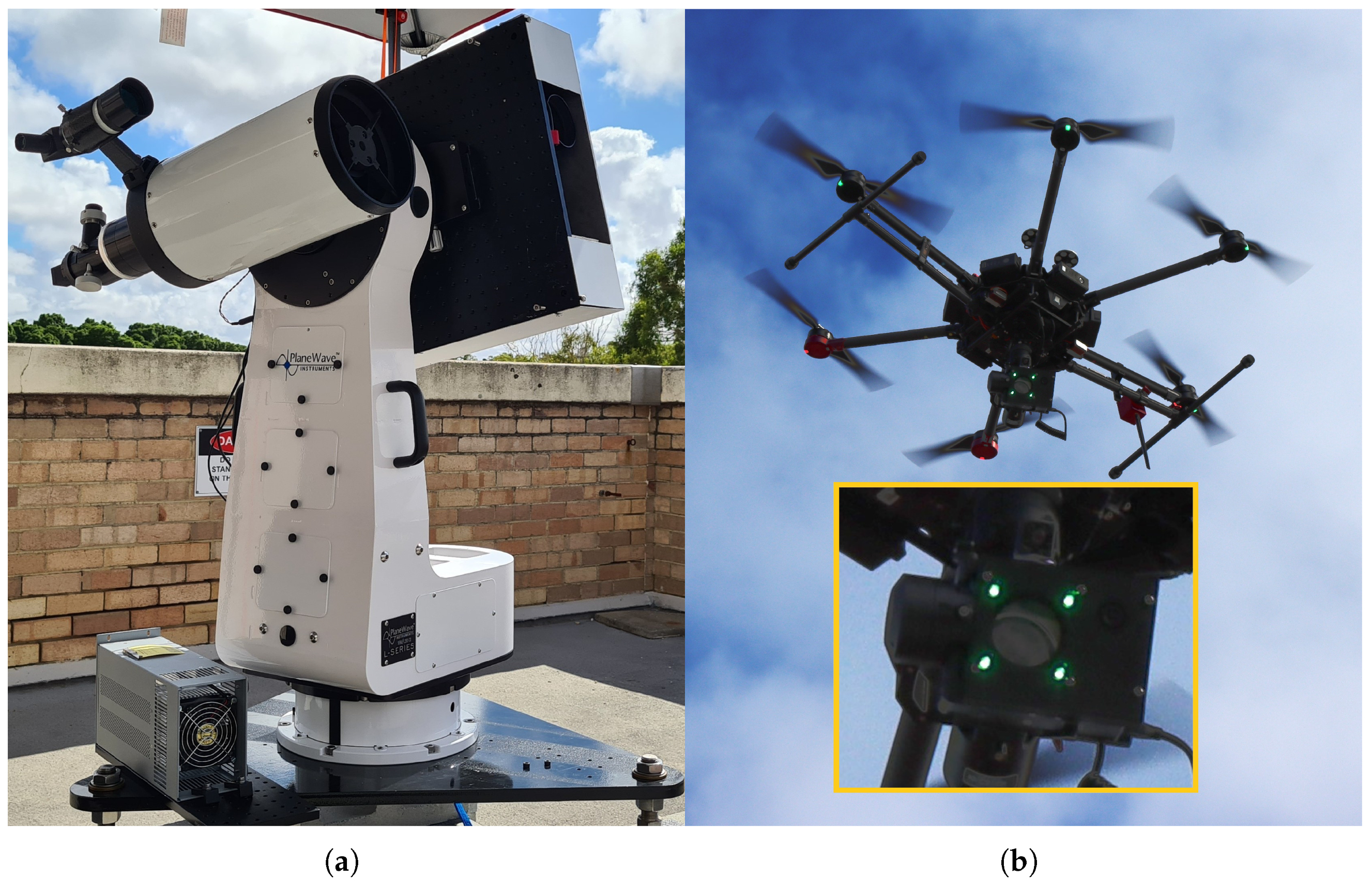
Figure 1 shows a photograph of the optical terminal in panel (a), alongside a photograph of the drone and drone-borne optical payload, in panel (b).
Figure 2 shows a detailed schematic of the optical systems. As the link segment is a folded FSO range, the transmitter and receiver hardware are conveniently located in the same cabinet and are isolated in fibre with an optical circulator.
2.1. Optical Systems
The optical terminal is a precursor to a field-deployable mobile optical ground station. Coarse pointing with the terminal mount (L-350, Planewave Instruments, Adrian, MI USA) is achieved with a machine vision (MV) system, comprising a visible-light camera, lens and single board computer, used to image the drone and payload. The drone-borne optical payload includes a square array of visible wavelength (green) beacon LEDs, arranged uniformly around the centre of the CCR. This beacon-camera arrangement feeds back to the MV system to automatically servo the mount when engaged, keeping the beam within the field of view of the optical terminal’s laser path. The field-of-view of the machine vision system is mrad, with an angular resolution of 9 rad.
The optical terminal also houses the FSO components for directing the laser beam. Optical signals from the transmitter are fed to the terminal using fibre. At the fibre-to-free-space collimator (FFC), the signal is launched into free space. This beam passes through a 50:50 beam splitter to a Galilean beam expander with a clear aperture of 43.5 mm. The beam splitter is required to image the returning beam, so half of the outgoing power must be directed to a beam trap and is lost. The outgoing beam is then steered by the tip-tilt (TT) mirror and stationary fold mirror, out of the terminal. The incoming retroreflected beam follows the same path, but this time half of the power is coupled into the fibre via the FFC, and then to the optical receiver. At the link distance, no clipping due to beam divergence is caused by the aperture of the CCR or the Galilean beam expander. Half of the incoming beam is directed by the beam splitter to the imaging arm.
In the terminal’s imaging arm, a lens focuses the incoming beam onto a 3 mm quadrant photodetector (QPD) with a field-of-view of mrad. Two position signals from the QPD are used to estimate angle-of-arrival variations and are input into a proportional, integral, derivative (PID) controller (one for each of the pitch and yaw mirror axes) and output to the TT mirror piezo actuators. The mirror has an actuation range of 4 mrad, covering the QPD field of view. Co-alignment between the QPD and FFC means the TT mirror provides high-frequency, narrow field-of-view pointing for fibre coupling.
Finally, the drone-borne optical payload also carries a camera to assist the drone pilot in pointing the payload towards the optical terminal. The optical payload chassis is a 3D-printed enclosure and mounts to the COTS gimbal controlled using the drone’s native software and controller.
2.2. Transmitter and Receiver Hardware
A PPM transmitter and receiver are implemented to demonstrate the capability of the system as a testbed for Lunar FSO communications systems. A field-programmable gate array (FPGA) development board (STEMlab 125-14, Red Pitaya, Solkan, Slovenia) generates a pseudo-random binary sequence (PRBS), mapped to a 4- or 16-order PPM waveform output. A high-slew-rate amplifier (THS3491, Texas Instruments, Dallas, TX, USA) matches the digital pin on the development board to the modulation port of a high-extinction-ratio optical amplitude modulator (MXER-LN-10, iXblue, Saint-Germain en Laye, France). A fibre-coupled seed laser (Koheras BASIK X15, NKT Photonics, Birkerod, Denmark) in the 1550 nm optical C-band is used, as it conveniently has polarisation-maintaining output fibre, avoiding polarisation-dependent losses in the modulator due to birefringence.
The transmitter PPM waveforms were measured over a 2 fibre link in a lab environment to determine the minimum possible slot width due to bandwidth limitations of components. At 16 and 8 slot widths, the transmitted pulses exhibit well-defined edges shorter than 1 . At 8 width, the raw bitrates with 4- and 16-PPM mappings (and guard slots) are 50 b/ and 25 b/, respectively. PPM symbols with 4 slot widths were tested but appeared distorted, most likely by the electrical transmission properties of the physical interconnect between the FPGA pin and the driver amplifier, limiting the achievable slot clock speed and, therefore, data rate. For the demonstration, the PRBS was framed into 15120 bit codewords, using the 4-PPM format with an 8 slot width. A faster slot clock could be achieved with a purpose-built electro-optical interface, to achieve the O2O-specified 260 b/.
The receiver hardware comprises a single-mode fibre (SMF)-coupled InGaAs photodetector (Menlo Systems FPD510-FC-NIR, typical to the coherent detection systems more often used by the group) and digitiser (ATS9360, AlazarTech, Pointe-Claire, Canada), with sufficient bandwidth to observe the PPM waveforms. An SMF-coupled detector was used as it was available, but a multi-mode fibre-coupled or free-space detector would be better suited, as PPM communication is not mode-selective. Slot and symbol synchronisation and demodulation are conducted offline in MATLAB. The incoming PRBS is used to measure the bit-error rate (BER) of a sequence of PPM symbols, provided the first eight PPM symbols in a record are received without error. As the incoming light is coupled to SMF, the PPM signal experiences fading from angle-of-arrival variations caused by turbulence, wind-buffeting of the drone, and mechanical vibrations of the optical payload. A variable optical attenuator was also added ahead of the photodetector to manually control the link margin.
2.3. Receiver Software
The offline receiver achieves slot synchronisation for a codeword by edge detection, for an initial estimation of slot boundaries in the record of photodetector output voltage samples. Symbol synchronisation is then achieved by overlaying and summing a number of un-synchronised symbols and identifying the guard slot as the slot with the lowest cumulative sum. Maximum-likelihood demodulation of each symbol is implemented by summing the voltage values in each slot location and selecting the slot with the largest value. If the signal is lost at the beginning of a codeword, synchronisation fails and the codeword is discarded. However, if the signal is lost after a codeword is synchronised, the demodulator has an equal likelihood four-way decision on the pulse slot location for a given symbol.
2.4. Receiver Performance
For 4-PPM with a typical maximum-likelihood detector [
23], errors arising from signal fade will lead to a
,
where
is the
Q-function and
is the signal-to-noise ratio. Analytical models for PPM error rates in terms of photodetector physics are complex to derive. In order to compare the demonstration data with this threshold, a simple model for
as a function of photodetector output voltage was developed for this demonstration. Three parameters are observed in the photodetector output voltage,
,
The photodetector voltage,
comprises the slot amplitude,
, an offset voltage,
, and additive white noise fluctuations,
, with zero-mean and variance
. The optical signal itself is assumed to be otherwise noiseless because of the high extinction ratio of the modulator. Therefore, the
for each readout is
where
is the mean squared value of the voltage corresponding to
or
sampled over the entire codeword.
2.5. Demonstration Operations
The optical terminal, transmitter and receiver were located on the roof of the Department of Physics building at The University of Western Australia at an altitude of 32 above sea level. The drone hovered at an altitude of 120 (the maximum allowed by local regulations, without exemptions), with a 650 m slant distance from the terminal site, completing the 1.3 km slanted folded link. While the drone was hovering, the pilot would use the optical payload camera to coarsely align the CCR with the optical terminal. At the optical terminal side, the drone was pulled into the MV system’s field of view by slewing the mount while viewing the MV camera feed. Upon entering the field-of-view of the machine vision system, the tracking system could be engaged, automatically moving the mount to locate the CCR within the field-of-view of the QPD. The TT system then dynamically corrected pointing errors. Operating concurrently, the two pointing and tracking systems effectively maintained fibre coupling while the drone hovered in place. If the TT system was disengaged by disconnecting the PID controllers, the MV system was not able to couple the laser light back into the SMF on its own, due to the beam size, link distance and wind buffeting of the drone.
3. Results
Results are presented for a drone flight conducted during the day on 18 March 2022, at 2:30 p.m. The wind speed recorded at the local weather station, Perth Airport, was ≈16.7 km/h [
24].
The link budget for the testbed is presented in
Table 1. The optical sensitivity floor for the photodetector was determined to be −33 dBm, corresponding to a mean output voltage of 1.4 mV. During measurements, the variable optical attenuator was adjusted such that the received power, after pointing losses, was near the threshold for error-free reception. Error-free reception occurred when the output voltage exceeded
, corresponding to an optical pulse power of
. Typically, less than one-third of the codewords were received without error, as the optical power received remained consistently above the −30 dBm error-free threshold due to angle-of-arrival correction by the TT mirror. At this link distance, the beam size is smaller than the Fried parameter and, therefore, scintillation due to turbulence was not expected to cause any fading in excess of the angle-of-arrival errors caused by drone movement and beam wander.
To confirm receiver functionality, BER was compared to Equation (
1) using observations for SNR per Equation (
3). The portion of transmissions received with bit errors, caused by partial or complete signal fading arising due to pointing errors, allow the receiver performance to be characterised.
Figure 3 shows the SNR as derived from Equation (
3) and BER for 720 codeword transmissions, with each data point representing a single 15,120-bit codeword. This record has a BER measurement sensitivity floor of 1/15,120 errors per bit, and a ceiling at
errors per bit, caused by failure to demodulate, though pulses were present. For comparison, the theoretical BER, from Equation (
1), is plotted alongside the data as a black line in
Figure 3.
4. Discussion and Conclusions
This demonstration involving a drone-borne CCR provided a useful return on experience towards FSO communications developments, including potential communication with O2O on a full-sized optical ground station. This was particularly true in the domain of flight operations, not otherwise accessible without enlisting the services of professional small aircraft operators, or operators of commercial high-altitude pseudo satellites or the few FSO communication-capable satellites in orbit. The drone link demonstration required the coordination of equipment and planning of methods within the research group and was subject to scheduling with the aviation authority and local government as well as uncontrollable go/no-go conditions such as wind warnings and rain. In effect, the availability of the drone provided a scaled-back simulation of space operations.
Interpreting Equation (
3) implies the optical sensitivity floor represented by
is analogous to background counts in photon-counting receivers, and a comparison may be drawn between the drone link and LLCD results [
25]. Downlink results from [
25] reported error-free communication at 38.55 Mb/s with a link margin of 13.5 dB between signal and background photon counts. Per
Table 1, the error-free link margin for the demonstration was 2.70 dB. While it is not possible for this testbed to recreate the transmission powers and link losses of a Lunar-to-ground link, the receiver may be similarly tested with the link margin at the limit of its sensitivity. This scales with detector technology, so a photon-counting detector with a lower sensitivity floor may be integrated into a future iteration of the testbed, and the receive power adjusted to recreate the link margin conditions.
Figure 3 shows a main cluster of BER versus SNR results following the theoretical relationship, confirming the expected performance of the receiver. However, the demodulation algorithm implemented often failed to completely demodulate a codeword if too many early symbols were faded, or if the slot or symbols synchronisation had failed, causing `synchronised’ pulses to fall across slot boundaries. These cases account for the outlying clusters at the top of the graph, stratified around BERs of 0.5 and 0.33, and indicate further margin for improvement of the offline receiver algorithm before investing engineering time into a real-time receiver.
The 1.3 km retroreflected drone link presented can be extended with materials and methods previously demonstrated over shorter retroreflected links such as verification of atmospheric channel modelling [
14]; demonstration of other communication formats [
15]; or demonstrations of modulating retroreflectors [
21]. Further extensions previously demonstrated include links to tethered drones, carrying active optical payloads [
20], or drones moving in paths tangential to the ground station, thus requiring the ground station to track at angular rates equivalent to satellite tracking [
16]. Furthermore, results from FSO communication demonstrations with stationary drones will be of interest to designers and analysts planning future terrestrial and disaster-response networks [
17,
18].
The drone provided a testbed to perform technical verification of the prototype communications equipment, intended for a future Lunar FSO communication link, over a real, time-varying channel. This also tests the mechanical robustness of the optical assembly and pointing systems. The effectiveness of the testbed is limited by dissimilarities to O2O in terms of modulation format and detector technology, as well as the relative differences in aperture sizes and optical power levels involved (intrinsically linked to detector technology and link distance). However, some of these limitations can be addressed with changes to the optics and launching the drone from a different location. Furthermore, without undertaking more fundamental demonstrations of capability, costly engineering upgrades to make the communications system more closely resemble O2O, such as the integration of photon-counting detectors, are risks and may not be supported by prudent systems engineering processes. The drone testbed will allow us to continue rapidly integrating and testing subsystems as work progresses to a more complete emulation of a cis-Lunar communication system. Therefore, this paper supports the case for retroreflected drone links as useful testbeds for developing FSO communication capabilities while access to FSO communications payloads in orbits remains limited.


 ,
, 


