1. Introduction
The electrical energy available in homes for domestic users (commercial and industrial facilities) is part of a large electrical system, which is indispensable in the modern economy. Often, the end user is not even aware of the energy generation and distribution infrastructure complexity that supports the most variable types of equipment in operation [
1].
The power distribution typically spans thousands of kilometers through varied vegetation and climate. As a consequence, it places high-voltage cables and other transmission components in very severe conditions that can result in corrosion, fatigue failure, and lightning damage [
2].
In this context, routine inspections followed by preventive and predictive maintenance have become indispensable, as they result in huge savings by avoiding unplanned interruptions in the energy supply [
3,
4].
Traditional power transmission line inspections have several approaches:
Transmission line climber: This is performed by a very well-trained and skilled person who is able to climb along the line to identify faults and perform routine maintenance. It is still used in the world, but the risk for the worker is immense. Furthermore, this work is sluggish and exhausting [
5].
Ground line inspector: The worker is equipped with optical equipment for the electrical transmission line inspection on foot. This approach is slow and there is a limitation on the inspector’s viewing angle [
6].
Inspection with landing vehicle: There are several variants of this modality. The most traditional one takes a mechanical lift coupled to the vehicle, where the line inspector approaches the line to perform the inspection and some possible small maintenance. Although quite accurate, this method is also dangerous and slow.
Helicopter inspection: An inspector equipped with an onboard camera in a helicopter performs inspections on the power transmission line. This method is fast and effective; however, it is expensive and requires highly skilled labor, such as a pilot and inspector [
7].
These traditional inspection techniques are very effective, but it is increasingly difficult to hire and train qualified personnel for this type of work [
8]. In addition, if more intensive inspections were carried out at a lower cost, the risk of interruptions would be reduced, providing a great economic benefit to the electricity distribution companies and to the consumers [
9,
10].
1.1. State of the Art and Related Works
The new transmission line inspection techniques have been developed over the last few years with great potential for improvement. Some cases occur with the replacement of traditional inspection techniques with helicopters and cars.
A quick search on the Internet shows many different techniques, which include Power Transmission Line Inspector Robots (PTLIRs). PTLIRs are autonomous or remotely controlled robots that have a wide variety of modalities and applications, involving a low cost, easy training of skilled labor for operation, and a low risk to the inspectors.
The next paragraphs will briefly describe some of the main inspection robots equipment for electrical transmission lines:
Climbing robots: They are capable of moving when coupled to the transmission lines, carrying out inspections and minor repairs and installing measuring equipment. These have been used on a large scale in recent decades and have been the focus of several types of research. The main operational difficulty is the obstacle transposition, inherent to the transmission line, such as spacers, dampers, aircraft warning balls, insulators, and towers [
11];
Fixed-wing UAVs: They are like small planes and their configuration can vary greatly. The most common are conventional configuration, dual boom, and flying wing, which are generally used to inspect large areas. As the flight speed is relatively high, they are not capable of hovering and it is not easy for them to investigate details (as helicopters are able to carry out) because they make quick passes over the target [
12,
13]. They are very useful for monitoring areas with vegetation growth in the vicinity of transmission lines, for example, thus verifying the need for pruning;
Rotary-wing UAVs: This is the most frequent type of robot application in the aerial inspection of transmission lines. As they are capable of hovering and can fly close to transmission lines, they can make more detailed inspections by going around the line to capture images from different angles. They can be configured with only one main rotor and one tail rotor, like helicopters, or they can have multiple rotors. Among the multi-rotors, the most used are battery-powered quadcopters or hexacopters due to their versatility and ease of construction [
14]. Despite being able to carry out more detailed inspections than fixed-wing UAVs (due to their low speed), they make extensive use of batteries, where many landings and take-offs are required to change these components [
15];
Vertical Take-Off and Landing (VTOL) UAVs: This type of aircraft combines the qualities of the two previous UAV topologies. The cost of a significant increase in the design complexity, systems allocation, stability, and control makes the latter much more complex mainly during the flight transition phase [
16]. The VTOL UAV greatly facilitates its operation when compared to a conventional fixed-wing aircraft. They are capable of covering large distances with agility at a low energy cost. If it identifies possible damages, it is able to transition to hovering mode for a more detailed inspection;
UAVs capable of coupling to the power transmission line: Also known as hybrid PTLIRs, they are designed by merging the technologies and skills of rotary-wing UAVs with those of climbing robots. They were carried out with multi-rotor platforms adapted to connect and move along the transmission line [
17,
18,
19,
20,
21]. The design and form of coupling to the transmission line still vary without a better approach being well-defined at the moment.
Under this background, it is possible to see a power transmission line inspection market overview and the new fronts of research, especially in the autonomous inspection sector. The last item, hybrid PTLIR, is a vast field to be explored in new projects, being the main topic discussed hereafter.
Although PTLIRs with walking and climbing capabilities have made significant progress over the last few decades, they still must deal with some limitations that reduce their practical operation, such as overcoming large obstacles of high-voltage towers [
22]. In addition, they will always be limited by the difficulty of placing and removing the robot coupled to the transmission line [
23].
On the other hand, traditional fixed-wing UAVs are widely used for aerial photography, security, mapping, and large area inspections [
12,
24]. Many studies and applications with rotary-wing UAVs have been developed for more detailed inspections [
25]. This last one has a considerable energy cost when hovering. In addition, when it uses the main and tail rotor configuration, it tends to be large and complex for maneuvering.
Regarding conventional quadcopter and hexacopter aircraft, they have a limited flight time: usually around 25 min of maximum flight time [
26]. Despite this, these configurations have become increasingly popular in inspection applications of all kinds, and also for transmission lines, as they tend to be easy to build and operate.
Alhassan et al. [
1] described in tables a summary of PTLIRs developed by many research institutes and technology companies around the world. For the climber robots category, they suggested that 8% of robots are not suitable for power transmission line inspections. Additionally, 69% of them are unable to avoid obstacles or require modifying the power transmission line by installing additional jumpers for each obstacle. Furthermore, 54% are difficult to place on the cable or carry on the power transmission line. Looking at the UAV category, the main restriction is flight autonomy, which ranges from 20 to 60 min. Furthermore, in an incipient way, some works led to the fusion of some of these technologies. In the end, the point of the main development is to hybridize the multi-rotor rotary-wing UAVs and the climbing inspection robot, which is the consequence of its ability to couple/move on the power transmission line, saving the battery supply and avoiding obstacles over them.
The first work reported in a scientific article was by Katrasnik et al. [
27], and describes a future hybrid PTLIR main architecture. It proposed a helicopter-like UAV with most of its subsystems in the undercarriage to allow for natural stability when connected to the power transmission line. Later, these same authors published more details in [
28], but there is no mention of a prototype that has been designed or built.
A hybrid robot prototype was designed and built using a drone platform DJIMATRICE 100 with a barycenter adjustment and the addition of a new undercarriage [
17]. This first prototype, weighing 4.235 kg, was created to perform landings on the overhead ground wire, where the front wheel drives the prototype along the wire, and every time it needs to cross a tower, it makes a small flight to overcome the obstacle. This small PTLIR, suitable for landing on small caliber cable, showed that this kind of operation leads to a significant power consumption reduction due to the amount of operation time when moving on the cable. It also pointed out that much work still needs to be carried out to optimize landing on the cable and operation under wind conditions, especially in case of shaking cable situations. These problems can be addressed by a more robust landing and coupling mechanism.
Some other authors describe research improving the coupling mechanism and conducting a finite elements methods simulation of components [
20] and dynamics modeling of the hybrid PTLIRs [
21]. This last one uses a different methodology for connecting it to the power transmission line, where the coupling mechanism is placed on top of the UAV and it approaches a cable placed overhead it. This same coupling method was used by Iversen et al. [
23], whose study describes the UAV approaching and sensors unit deployment. The coupling mechanism on top of the PTLIRs has the advantage of always having a stable condition when connected to the power transmission line, not needing to place the aircraft’s center of gravity in a lower position. On the other hand, it adds more complexity to the coupling mechanism and a more difficult approach to the cable. Another disadvantage of this strategy was pointed out by Skriver et al. [
3], who describe potential failures during operation below a live overhead power line.
Meanwhile, a more advanced hybrid PTLIR was designed by Hydro-Québec, which aimed to land and scroll on the power line conductors with a voltage rating of 315 to 735 KV and its diameter varying from 19 to 35 mm [
18,
19]. This PTLIR weighs 14 kg without any payload. This commercial design has a similar overall architecture to the PTLIR that will be presented in this current research,
Section 2, with a low center of gravity providing natural stability on the wire. In the conclusion of the paper, [
19] appointed future work on some landing tests in a cable no longer assumed to be horizontal. A more realistic angle of the cable during landing on the field measures around 10 to 12 degrees. This shall prove to be a difficult task since this PTLIR has a two-roller configuration of the coupling mechanism. To facilitate the task, the approach for landing should have a pitch angle of around 10 to 12 degrees to match the cable angle more easily, providing a smoother landing. Thus,
Section 1.2 proposes a new PTLIR to tackle the landing on a sloping cable due to its over-actuated capability.
Furthermore, an over-actuated system has more control inputs than necessary to achieve a given set of outputs. Solving such systems usually requires nonlinear control allocation methods, which can be computationally demanding and difficult to embed on small UAVs. In this study, a control allocation approach based on the author’s previous work was used [
29,
30]. This method breaks the nonlinear system into a set of linear problems, making it computationally efficient and suitable for use on a small platform drone.
1.2. Contributions
A fast search on the Internet brings about some important conclusions about PTLIRs. They have a wide range of applications, from electrified power transmission lines to overhead contact lines [
31,
32], not only for autonomous, cheap, and safe transmission power line inspection.
During the construction phase of the power transmission line, there are plenty of tasks that can be carried out by an aircraft such as a hybrid PTLIRs, such as: laying the primary guide rope [
33,
34], mapping the terrain condition, monitoring the work, and inspecting the newly constructed power transmission line to find damages in the conductor that may be caused by the large local stress during the construction [
35].
In the construction phase, the conductor passes through a set of string pulleys that can damage the conductor, and this will impact its durability within the operation time [
36]. Although there are researchers proposing a new design stringing equipment that avoids damaging the conductor [
37], it is not widespread yet. Even though models and experiments for evaluating the stress, tension loads, and friction of the conductor passing through the pulley can be found, there are still relatively few research studies on these subjects [
35,
38].
From this perspective, this work aims to present a newly over-actuated Hexacopter Tilt Rotor (HTR) UAV designed for monitoring the stringing phase and also, after construction, executing inspections in the cables while coupled to the power transmission. The use of a UAV enables the identification of possible damages due to the large local stress that has been generated during the conductor’s setting out.
The main attributes that this over-actuated aircraft shall have are written below:
The capability to static hover and descend on a variable pitch angle (attitude). This allows the aircraft to adjust to the local catenary angle, providing a safe landing on the transmission line cable;
A high flight maneuverability, especially when approaching the power transmission line;
A simple and lightweight way to move along the cable, only adjusting two propulsion motors;
A reliable coupling mechanism for landing on the power transmission line;
A stable operation over the cable.
The first three aircraft attributes will be fulfilled by a new tilt-rotor topology that gives it an over-actuation. The fourth one is obtained after a new coupling subsystem. Regarding the last one, it is generated by the meticulously designed overall UAV architecture.
The contributions of this paper are a consequence of previously published works by the authors, which have been studied for a long time. The main area of research concerns the aerial vehicle, coming from traditional multi-rotors to tilt-rotors, modeling, fault-tolerant control, controller design and tuning, and electromagnetic inference on the UAVs, among others [
16,
29,
30,
39,
40,
41,
42,
43,
44,
45,
46].
1.3. Paper Organization
The paper is organized as follows:
Section 2 describes the UAV in detail, technical specifications, and all of its subsystems.
Section 3 presents its kinematics and dynamics modeling for the normal mode and the coupled-to-power-transmission-line flight mode.
Section 4 depicts the overall control structure, with all characteristics for both flight modes.
Section 5 shows the simulation results. At the end,
Section 6 concludes the work.
2. HTR UAV Description
As a very unique contribution to the hybrid PTLIRs evolution, this new UAV design is proposed to merge an advanced hybrid PTLIRs configuration in an over-actuated platform by using two tilt rotors placed on opposite sides of the UAV lateral. Using some parts of FLYD-100 V2, a tilt-rotor system and a new undercarriage were designed to reach the requirements to land and move on the power transmission line. The total height of the aircraft is 502 mm, the distance between rotors is approximately 994 mm, the distance between left and right landing gear is 450 mm, and the total mass without the payload is approximately 9.1 kg.
The over-actuated tilt rotors enable a very fast reaction to the commands when in flight. They are responsible for moving the UAV along the cable when connected to the power transmission line.
The reason for the high maneuverability in forward dynamics is the consequence of the tilting of the motors (only in this direction) instead of pitching down the aircraft, i.e., it turns only the rotors that have much smaller moments of inertia than the whole UAV. In addition, it gives a high-speed capability for minor trajectory adjustments. Furthermore, if the tilt rotors are tilted in opposite directions, the UAV presents quick yawing maneuvers, which also offer much bigger torques than the traditional reaction torque balance.
When moving connected to the power transmission line, there is no necessity to control rolling dynamics due to the natural stability. This was determined by simply placing the batteries in the landing gear supports, pushing the low center of mass downward. Regarding pitching movement, it follows the catenary angle of the conductor cable due to a set of two conical rollers in contact with it.
During the approximation flight for landing on the power transmission line, it is indispensable to use the tilt rotors, and also when landing in an arbitrary place of the catenary. Owing to the fact that a random point in the catenary has an inclination angle different from the horizontal, the UAV is able to stabilize at a certain pitch angle to match the catenary’s local angle. In addition, this is a very difficult task for a conventional multi-copter.
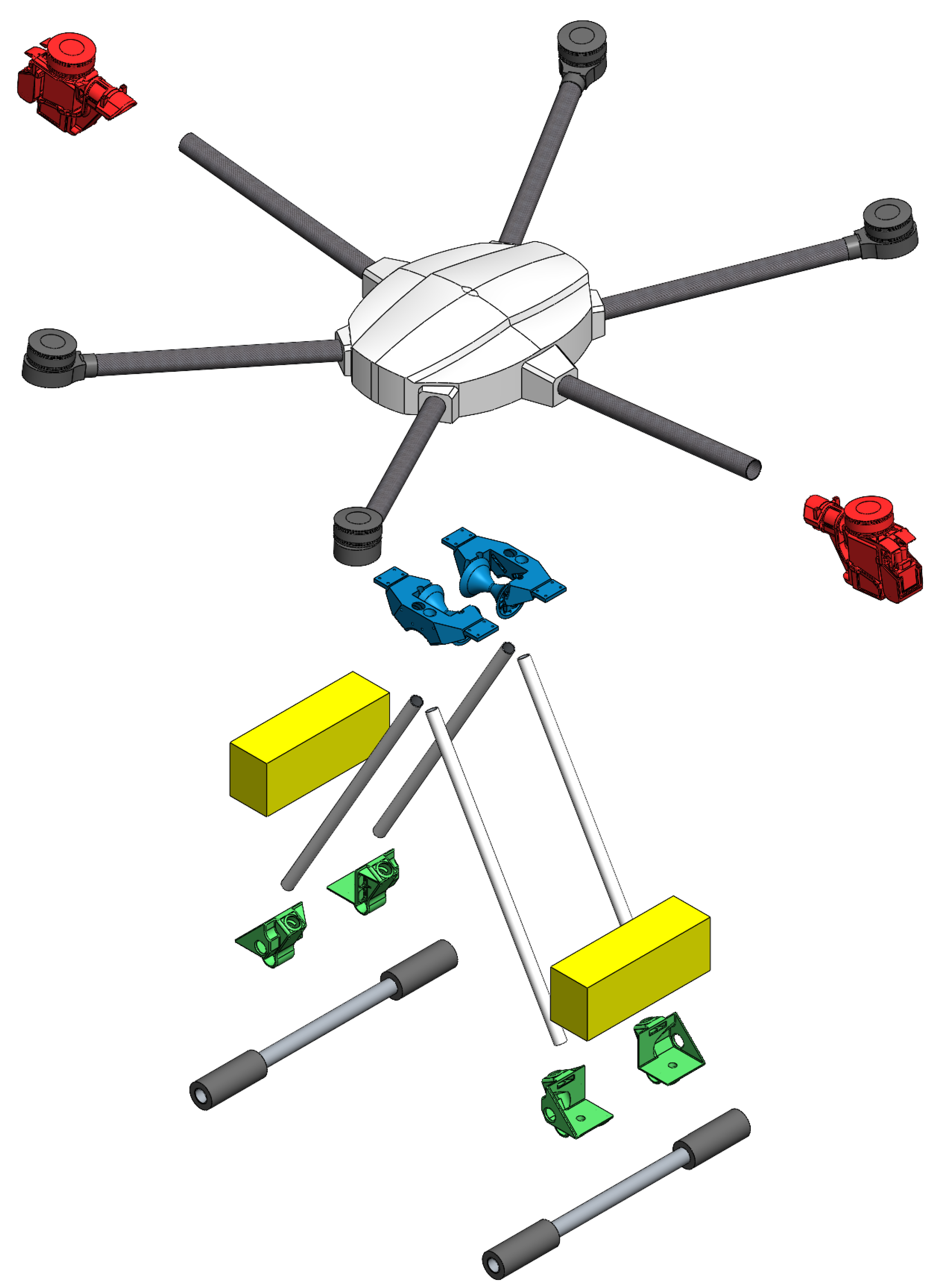
Figure 1 shows an exploded view, where each color represents a different subsystem, respectively.
The red color depicts the tilt-rotor subsystem (represented by rotors 1 and 2), totaling six. They are directly connected to the UAV’s central part through the arms made of carbon fiber tubes. The blue subsystem represents the coupling mechanism responsible for connecting the UAV to the transmission line cable. It is also accountable for attaching the landing gear’s legs to the UAV main body. The battery support that, in addition to supporting the battery, connects the landing gear to the landing gear legs, is shown in green. The battery itself is represented by the yellow subsystem.
To better illustrate the developed prototype,
Figure 2 shows a real picture of an HTR landed on a transmission line cable, where it is possible to observe two propulsion motors tilted
degrees:
2.1. Coupling Subsystem
The coupling subsystem is basically composed of a prop that connects the landing gear to the UAV ventral region and to the conical rollers (supporting the aircraft when it is resting on the transmission line). It is simple, and its very effective design was developed to reach the heavy demands of the landing gear. In addition, the landing gear tubular structures have a second function, which is guiding the transmission cable to the region of the conical rollers (they are also positioned on the same support). Thus, as a single structure performing many tasks using the minimal solution design philosophy, it also tends to have very light components.
Figure 3 shows the coupling subsystem with the multi-functional support represented by item 1. This is positioned on the front and back, with two identical mirrored pieces.
Once the UAV is coupled to the line, it easily moves with minimal friction due to a conical roller, which was developed to support the aircraft loads (represented by item 2 in
Figure 3). The axle is made of a carbon fiber tube of 8 mm diameter and 1 mm thickness (internal to the conical roller) and is supported by two bearings for each axle, indicated by item 5 of
Figure 3. The arc-shaped structure supports the bearing (bolted directly to the multi-functional support), represented by item 4 of
Figure 3. The landing gear tubular structures are represented by item 3 of
Figure 3.
2.2. Tilt Rotor
Two tilt rotors are placed on opposite sides of the UAV lateral, rotating over the
Y-axis. They are able to tilt
forward and backward. The left-side tilt rotor (motor number 2) is represented in
Figure 4, and has a positive orientation tilted forward (to the red arrow). Regarding the right-side tilt rotor, it is computed in the opposite direction.
When there is a positive angle for the left-side tilt rotor and a negative angle for the right-side tilt rotor, the UAV will move forward in the positive X-axis direction, and when deflected negatively to the left-side tilt rotor and positively to the right-side tilt rotor, the UAV will fly in a backward direction. On the other hand, if both tilt rotors obtain positive or negative deflections, the aircraft tends to spin around the Z-axis direction, i.e., it performs yawing maneuvers.
A new design of a tilt rotor was proposed to avoid complexity such as gears [
47]. The support of the motor is directly connected to the servomotor, resulting in a very simple design, as shown in
Figure 5.
However, the motor position must be preserved with a pivoting axis fairly aligned to the carbon fiber tube arm. For that, the servomotor base is supported in a lower position as shown in
Figure 5, where the servomotor base is represented by item 3.
Figure 5a shows the exploded view of the rotor deflection subsystem 1 and 2, where each component is marked. The carbon fiber tube that serves as an arm to give clearance for the rotor from the central region of the drone is represented by item 1. Item 2 represents the servomotor responsible for the displacement in the propulsive motor’s angle. The servomotor base is represented by item 3. Item 4 is the motor that connects it directly to the propeller. Item 5 represents the servomotor arm. On the other side, item 6 represents the carbon fiber tube lock. Item 7 represents the bearing that supports the motor mount represented by item 8. Finally, item 9 represents the motor’s electronic speed controller.
Figure 5b shows the assembled design of the tilt-rotor mechanism.
Figure 5c shows the prototype’s real view.
3. UAV Kinematics and Dynamics Modeling
This section will describe aircraft kinematics and dynamics modeling, taking the normal flight mode into consideration.
Some UAV variables are measured in the vehicle frame
, whereas others are measured in the body-fixed frame
and inertial frame
. Typically, UAVs use the following state variables in North-East-Down (NED) nomenclature, as previously mentioned: the vector
represents the inertial north, east, and altitude coordinates of the aircraft Center of Gravity (CG) along axis
,
and
in the inertial frame; the vector
represents the roll, pitch, and yaw angles in the vehicle frame (
,
,
). The vectors
represent the three-dimensional linear and angular velocities over the axes (
,
,
) in the body frame. Then, as the HTR rotates around its axis, angular displacements are presented, named as roll (
, rotation around
), pitch (
, rotation around
), and yaw (
, rotation around
) angles, respectively. This representation was based on works [
29,
30].
The tilt rotors give the HTR a very unique flight characteristic, which is the ability to move around the transmission line in the coupled mode.
Taking this into account,
Figure 6 shows the rotation direction of each HTR’s motor.
The rotors marked in green (1, 3, and 6) spin in a clockwise direction. The rotors marked in blue (2, 4, and 5) spin in the counterclockwise direction. The red arrow represents the htr’s nose. Rotors 1 and 2 are the only two rotors that can be tilted. Tilt rotor 1 moves at a positive angle when moving backward, so in the opposite direction to the red arrow of
Figure 6. Regarding tilt rotor 2, it moves at a positive angle in the same direction as the red arrow, forward flight. Therefore, both tilt rotors in the positive direction result in torque in the positive
Z-axis direction, downwards.
The thrust produced by each rotor is proportional to the square of their respective angular velocity [
48]. According to experimental tests, it can be considered that the propulsion force is directly proportional to the signal driven to the motors. Equations (
1)–(
5) show the respective forces and torques for motor 1 as an example:
where the
p index denotes that the parameter corresponds to the propulsion system,
is the signal of motor 1,
are the propulsion forces generated by motor 1 in the
and
axes,
,
are the torques generated by motor 1 along axes
,
,
,
is the constant of propulsion characteristic to each system (set of motor, electronic speed controller, and propeller),
m is the HTR arm length, and
is the height of the propulsion plane from the CG (seen in
Figure 7). Due to Newton’s third law,
is the reaction moment constant due to the propulsion system rotation.
After the test bench experiments, each rotor of this specific HTR produces N and Nm.
In the special case of the tilt rotors, represented by rotors 1 and 2 of
Figure 6, they also consider their tilting angles, denoted by
, where
j is the respective tilt rotor (1 and 2). Therefore, the force generated by the tilt rotors in the
X-axis direction can be represented by
(rotor 1) and
(rotor 2). Regarding the
Z-axis direction, their forces are described as
(rotor 1) and
(rotor 2), highlighting that the
Z-axis points downwards. For the remaining rotors (from 3 up to 6), their forces are described as
. These definitions are essential for understanding the Control Effectiveness Matrix (CEM) construction of the two flight modes.
Furthermore, when the HTR is in normal flight mode, it is referenced in its center of gravity, which is located 148.6 mm below the base of the HTR central part. In other words, it is equivalent to the sum of
c and
d in
Figure 7.
The height mm shown above is taken from the center of a cable to the base of the HTR central part. This reference is taken as 47.9 mm and is the point at which the HTR swings laterally when connected to the power line. The CG is located mm below the rotation point when connected to the cable. These characteristics give the drone a naturally stable condition.
It is important to highlight that the small angle that the HTR arms make with the XY-plane resembles a positive dihedral, which, in this specific case, is negligible due to the forces cancellation of the rotors of the opposite side.
The next two sections will present the different HTR modeling considering the flight modes:
Section 3.1 (normal flight mode) and
Section 3.2 (coupled-to-power-transmission-line flight mode).
3.1. Normal Flight Mode
As previously mentioned, the HTR state variables are measured in different coordinate frames. It is common in the literature to present them as the vehicle position defined by the vector
in the inertial frame
. Its angles are defined by
in the vehicle frame
. Moreover,
and
are the linear and angular velocities, measured in the frame
. According to Fossen [
49], Equations (
6)–(
8) are presented:
Regarding the velocities, Equations (
9)–(
11) are formulated:
where
is the generalized velocity vector,
is the linear velocity vector, and
is the angular velocity vector, both in
.
The six Degree of Freedom (DoF) rigid body kinematics and dynamics model is expressed in Equations (
12)–(
14):
where
is the velocity vector in
,
and
are the linear and angular vectors in
, respectively, and
,
, and
are the transformation matrices that relate
,
, and
.
The HTR dynamics are described by differential equations from the Newton–Euler method, such as that shown in Equation (
15):
where
is the system inertia matrix,
is the Coriolis-centripetal matrix in frame
, and
are the gravitational and propulsion resultant vectors, respectively, compounded of forces and torques, both in frame
.
In a more detailed representation, Equations (
16)–(
20) are shown, also with the HTR inertia matrix
[kg.m
2] [
29,
30,
48]:
where
,
and
. The index
is related to the gravitational force, and
is referred to as the propulsion system, both in a respective axis.
Furthermore, to conclude this section, Equation (
21) presents the normal flight mode CEM with all forces and torques generated by the five Virtual Control Actions (VCAs) and eight RCAs of the HTR.
where
and
.
3.2. Coupled-to-Power-Transmission-Line Flight Mode
This section will depict the HTR model coupled to the transmission line, where the UAV stability is described in the function of the cable position in reference to the uav, i.e., it considers the coupling subsystem position. To better illustrate the controlled DoFs and variables,
Figure 8 also presents the axis rotation and VCAs:
As shown above, the coupled flight mode reduces the HTR kinematics and dynamics modeling into only two DoFs, which are rolling dynamics (rotation around the axis) and displacements along the X-axis (translation along the axis).
Some important explanations for that are summarized below:
Propulsion force is no longer necessary due to the fact that the HTR has landed on the power transmission line;
The HTR design and its constructive characteristics make the rolling dynamics perform a kind of “simple pendulum”. The reason for this is that the aircraft CG is under the aircraft center of rotation;
Pitching and yawing torques,
and
, respectively, are not controlled because of the two rollers of the coupling system, as shown in
Figure 3. Therefore, they make the HTR remain at
degrees with the cable and at the same angle
with the power transmission line angle
, as the catenary position is changed.
Figure 9 explains this better.
3.2.1. Modeling of Rotation around Axis
This DoF is defined as the HTR rotates over the transmission line cable after landing. The function in the UAV
axis is described in Equation (
22). It is also presented in Equation (
23) through a simplified and linearized differential equation, according to the mechanical vibrations literature [
50,
51]:
The inertial portion of the equation is described by the polar moment
kg.m
2 with the angular acceleration
in the
axis. It is important to highlight that
is slightly different from
presented in Equation (
20), which is a consequence of its different pivoting position.
The damping portion of Equation (
23) was substantially simplified and linearized from the aerodynamic damping (
) and Coulomb damping (
), which was adjusted in a single linear general damping constant
Kg.m
2/rad.s and its angular velocity.
The restoring moment was linearized by considering small signal approximation . All these simplifications contribute to an easy computation of the HTR lateral stability without accuracy loss regarding its controllability.
The external moment is usually associated with winds that the aircraft may be subjected to once connected to the power transmission line. It is also in this part where the actions are considered when controlled flights are performed.
3.2.2. Modeling of Translation along axis
This dof is defined as the HTR moves along the transmission line cable for the entire catenary. Then, this characteristic is described in Equation (
24):
where
x and
y are the horizontal and vertical directions, respectively, and
a is the ratio of the weight per unit length of the cable with
, described by
and the tension in the horizontal direction
.
It is important to highlight that
x and
y variables can be approached as
and
, respectively, from Equation (
16). For this flight mode, the HTR modeling is totally different from the normal one, which needs the free-body diagram theory.
Furthermore, when the drone has landed on the cable, it normally operates with the tilt-rotor motors (numbers 1 and 2 of
Figure 6) from a maximum angle of
degrees in relation to its vertical axis.
When these tilting motors are turned off, the HTR will naturally move to the catenary lowest point, which is assigned to be the horizontal coordinate origin described in Equation (
24). As the power of the motors increases, the drone moves along the catenary until the condition of maximum power.
Then, the thrust force of tilt-rotor motors as a function of the catenary position can be described as:
The variables described here can be seen in
Figure 9, where
P is the aircraft weight,
N is the normal force of the rollers in contact with the cable, and
is the thrust force of the tilt rotors along the
axis.
The angle is the angle tangential to the catenary in relation to the ground. Then, it increases as the HTR moves from the catenary’s lowest part toward the towers, which is the catenary’s highest point.
For the specific conditions in this work, the maximum angle that the HTR is able to reach was approximately 42 degrees, as described in Equations (
25) and (
27). However, the rollover condition—that is, the drone pivots over the front due to the generated moment—was approximately 40 degrees, explained by the distance from the roller axis, the vertical distance from the center of mass, and the tilt rotors.
Then, as presented for the normal flight mode, Equation (
28) presents the CEM for the coupled-to-transmission-line flight mode with all forces and torques generated by the two VCAs and eight RCAs of the HTR.
4. Control Loops
This section will present the control loop specifications before presenting the simulation results. It also depicts some important topics about linear and nonlinear controllers applied to UAVs.
Numerous studies employ linear controllers, specifically the Proportional, Integral, and Derivative (PID) controller, to stabilize UAV flight. For instance, Patel and Barve [
52] employed Proportional and Derivative (PD) and PID controls to achieve this goal. Thums et al. [
53] confirmed that the PID controller displays robustness when operating in a closed loop under conditions of uncertainty and perturbations.
Based on experimental results reported in Hoffmann et al. [
54], it can be inferred that while the PID controller yields satisfactory outcomes, its effectiveness is limited to simple trajectories, low speeds, and indoor settings. When the quadcopter is exposed to higher velocities and wind disturbances, the results demonstrate that the PID control technique is inadequate for accurately tracking trajectories.
Bouadi et al. [
55] argue that both linear and non-linear control approaches rely on the precise and well-defined modeling of quadcopter dynamics. Furthermore, they stress the importance of utilizing adaptive control algorithms when designing flight control systems. Such algorithms are necessary not only for enhancing the performance and reliability but also for handling external disturbances, uncertainties in aerodynamic parameters, and inaccuracies in the model.
Lopez et al. [
56] utilized adaptive control with sliding mode tuning to stabilize the altitude of the UAV. In contrast, other studies integrate adaptive control methods with artificial intelligence to establish the system’s control law. For example, Aruneshwaran et al. [
57] employed a combination of back stepping and neural networks to decouple nonlinearities from the system and minimize uncertainties in the stability function.
Other controller topologies can also be used in UAVs—they are not restricted to those mentioned above—such as fuzzy, H-infinity, and quadrature oscillators, used by the authors Zsuzsa et al., Rigatos et al., and Mathur et al. [
58,
59,
60].
Regarding the proposed controller, it was designed for two different flight modes, which are normal and coupled-to-transmission-line flight modes. Regarding the normal flight mode, which means the entire flight before landing on the transmission line cable, the whole control structures were based on previously published works from the authors Santos et al. and Silva et al. [
16,
29,
30,
40], considering Proportional (P)-PID controllers with Successive Loop Closure (SLC).
The main reason for choosing the P-PID controller topology for the proposed HTR UAV is its simplicity and low computational requirements. Additionally, the Pixhawk Px4 control board embedded in the aircraft does not support highly complex real-time routines. Due to this limitation, a previous control allocation developed by the authors, named as fast control allocation ([
29,
30]), was used instead of traditional nonlinear control allocation.
The implemented controller topology allows the vehicle to perform maneuvers using differential torques on all six propulsion motors and/or tilting their two servomotors, directly coupled to propulsion motors 1 and 2, independently. All other subsystems described in
Section 2 are not affected directly by the controller because they are not parts of HTR actuators. This type of possibility leads this vehicle to be faster, more versatile, and have great torque application, among other benefits.
Further detailing the last explanation, the P-PID controllers for yawing and forward/ backward velocity along the axis act directly on the servomotors. The controllers for propulsion force (along axis), rolling, and pitching perform their actions in the propulsion motors.
Table 1 presents the controller gains that were tuned for the six controlled DoFs during normal flight mode. The controller tuning was based on the linear model using the methodology proposed by the works of Beard and McLain [
48] and Santos et al. [
30]. By using this approach, it was possible to achieve the system’s controller gains.
Regarding the coupled-to-transmission-line flight mode, as previously mentioned, the HTR modeling was reduced from six to two controlled DoFs. To illustrate the control loops in a simplified picture,
Figure 10 shows the htr overall control structure, also with the control allocation task:
Considering the above figure, it is possible to see that the control loops were implemented considering two parallel levels: high-level loops (circle number 1) and low-level loops (circle number 2). The high-level loop runs at 80 Hz and is responsible for controlling the inertial position loops (), which deliver virtual control action. The low-level loop runs at 400 Hz and deals with the angular position loop (), presenting virtual control action.
Circle number 3 represents the control allocation technique described in Santos et al. [
29,
30].
Furthermore, every control loop level has two feedback cascade structures, external and internal, presented in
Figure 11:
The outer one is a position control loop (with a P controller) and the inner one is a velocity control loop (with a PID controller), also taking SLC into account.
The external controller is in charge of the position stability of the controlled variable through the controller P. Thus, the output control action P is the internal control loop input PID in cascade [
61]. It is essential to highlight that the output from the external loop is in the inertial referential frame
, which is translated to the body-fixed frame
before being used in the internal one.
In the integral loops, a saturating block was inserted, functioning as an anti-windup action, preventing the final control action saturation obtained only from the integral action.
To finish the control aspect information from
Figure 11, Low-Pass Filters (LPFs) were implemented to mitigate the abrupt derivative control actions, created to pass signals with a frequency lower than the cutoff frequency and inhibit the passage of signals with frequencies higher than this frequency (five times slower than the cutoff frequency of the respective control loops).
Table 2 presents the controller gains that were tuned for the two controlled DoFs (rolling and forward/backward velocity) following the same controller tuning approach used for
Table 1:
5. Simulation Results
The simulation results only focus on scenarios where the HTR is coupled to the transmission line. The normal flight mode results are similar to the other previous papers published by the authors Santos et al. [
29,
30,
39].
They are divided into two different scenarios: a flight that stops in the catenary specific x-coordinate (
Section 5.1) and a flight for the whole catenary course with non-zero roll angle setpoints (
Section 5.2).
The first one aims to show that the HTR can stop everywhere in the catenary and also perform the desired zero roll angle, i.e., . Furthermore, the position and velocity are controlled in both scenarios.
Regarding the second one, it aims to show the possibility of making inspections around the cable, and also rotating the onboard camera.
Furthermore, the catenary characteristics were considered to be 500 m and the ratio was considered to be
. This results in a catenary characteristic with 22 m as the approximate difference between the highest and lowest point and almost
degrees of the maximum tilting pitch angle. This catenary angular range is easily found in the field, as written by Hamelin et al. [
19].
The following htr constructive characteristics were chosen:
Maximum linear velocity along axis: km/h;
Maximum rolling angular velocity along axis: deg/s;
Maximum amount of propulsion force for motors 1 and 2: N;
Maximum amount of rolling torque for motors 3, 4, 5, and 6: N.m;
Servomotor tilting angles are always degrees when forward/backward movements along the catenary are necessary. The reason for this is to optimize the motor propulsion energy.
In this study, the control performance specifications were defined to ensure that each controller achieves the maximum speed of the UAV in each DoF as quickly as possible while maintaining stability throughout the maneuver. To meet these specifications, the controllers were designed to prevent overshoots and minimize steady-state errors, thus ensuring the precise control of the UAV. Overall, these specifications were critical for achieving a smooth and efficient flight HTR UAV performance.
It is also important to mention that all simulation tests used an Intel(R) Core (TM) i7-2600 device with 3.4 GHz 8 GB of RAM and Windows operational system 7 with 64 Bits.
5.1. Scenario 1
This scenario was prepared to show a case where the HTR will stop at a catenary x-coordinate, i.e., it will stop at a point where it is necessary to tilt the servomotors to balance the HTR’s weight component. The results are presented in
Figure 12.
The desired roll angle for the whole experiment was zero (
degrees), where the htr starts from the top of one power line tower (green x) and follows (red line) the catenary shape (blue line) until it reaches
m in x-position (black circle), in the direction of another power line tower, as shown in
Figure 12a.
Figure 12b presents the controlled responses for the catenary position (
x), roll (
), pitch (
), and VCAs (propulsion force along the
axis (
) and rolling torque (
)).
Then,
Figure 12c shows all eight RCAs necessary to perform this scenario, where
is the normalized RCA ([0–1]) for each propulsion motor
i, according to the layout presented in
Figure 6:
Figure 12a gives an interesting two-dimensional perspective of the HTR following the whole catenary. It also shows the start and end points, where it is possible to see that the aircraft stopped in an ascendant x-position. The aim was to show the necessity of the servomotors compensating for the weight component in the opposite direction of the HTR body-fixed frame.
Regarding
Figure 12b, the first graph (catenary coordinate
) demonstrates that the HTR could reach the desired position
m without an overshoot with a constant velocity. The second graph shows that the roll angle was kept as
after the beginning, during the whole test, in order for it to be possible to check whether any VCA
was requested after 1 s (fifth graph). This is explained by the null initial state conditions, where the HTR controllers need some time to stabilize all DoFs at the same moment. The third one depicts the pitching angle during the test, where it started at −10 degrees, and, in the
position, it stabilized around
degrees. The fourth graph illustrates the necessity to compensate for the HTR’s weight component as the catenary x-position changes. In the beginning, the controller requested a forward force to reach the maximum linear velocity along
axis and, after, the VCA
started to have negative forces. Then, around
s, it becomes positive again, which is crucial for starting the catenary ascendant part. To stop in the desired catenary x-position, the controller requested negative force
around
s, stabilizing just after with a positive value.
Figure 12c can ensure some aspects written in the previous paragraphs, such as the exact moment when a negative or positive VCA
is requested, by the combination of motors 1 and 2 (red lines) and servomotors 1 and 2 (black lines), as well as when the desired catenary x-position
is reached.
It is also possible to note the zero RCAs in motors 3, 4, 5, and 6 (blue lines) after a 1 s simulation due to the non-VCA request. It is important to highlight that these rolling torques are quite negligible considering that their available range is N.m for the four propulsion motors.
5.2. Scenario 2
This scenario aimed to present a situation where the HTR navigates through the entire catenary path, i.e., it will fly between two towers without any stop. It is also possible to analyze its behavior when going down and up with desired non-zero roll angles. The results are presented in
Figure 13.
Figure 13a presents the controlled responses for the catenary position (
x), roll (
), pitch (
), and VCAs (propulsion force along
axis (
) and rolling torque (
)).
Then,
Figure 13b depicts all eight RCAs necessary to perform this scenario, where
is the normalized RCA ([0–1]) for each propulsion motor
i, according to the layout presented in
Figure 6:
The first graph of
Figure 13a (the catenary coordinate
) shows that the HTR could reach the desired position
m again without overshoot at a constant speed. This point is exactly the top of the second pylon. The second graph shows the roll angle during the whole test, where 20 degrees was requested in 20 s. At 50 s of the simulation (around the catenary x-position of
m), −40 degrees of roll was performed, moving to −20 degrees of roll. After that, at 80 s, the rolling angle returned to 0 degrees. It is important to note that all the roll setpoints were executed with smooth setpoint transitions. The maximum roll angular velocity was 5 deg/s. In addition, all overshoots were observed for the roll dynamics. These roll responses can also be seen by examining the corresponding VCA
in the last graph of
Figure 13a.
The third graph of
Figure 13a depicts the pitching angle during the test, where it started at −10 degrees with an
250 m position, and finished with 10 degrees in the
m position. The fourth graph also reflects the necessity to compensate for the HTR’s weight component as the catenary x-position changes. In the beginning, the controller requested a forward force to perform a maximum linear velocity along
and, after, the VCA
came to have negative forces. Then, as for the first scenario, around 43 s, it became positive again, which is necessary for the catenary ascendant stage. To stop in the second power line tower (
m), the controller requested negative force
around 100 s, stabilizing just after with a positive value.
Figure 13a reaffirms the maneuvers mentioned before, not only by the angle combination of servomotors 1 and 2 and the rotation of motors 1 and 2, but with the respective rotations for motors 3, 4, 5, and 6. Furthermore, these four last motors were only turned on where the VCA
was necessary for controlling roll dynamics, making it energetically efficient.
6. Conclusions
This work proposed a new design of an UAV capable of coupling to the transmission line cable. It aimed to solve some problems of the state of the art pointed out by the extensive bibliographic review, performed by power transmission line robotic inspections.
A simpler coupling subsystem was also designed with an over-actuation HTR capability. The over-actuated UAV’s controllers improved the maneuver capability and provided the necessary traction for its displacement on the cable.
The time spent on the power transmission line cable inspection has a substantial effect on the battery consumption once it uses much less power in this operational mode when compared to UAVs for traditional flying inspections. When it is close to the cable, it gives a much more accurate inspection capability once it can make 360 degrees scanning by placing cameras on the UAV body and landing gears. Furthermore, it is possible to compare it to climber robots and/or other types of hybrid PTLIRs, where the proposed tilt rotor gives it much more agility on the cable and a quick transition between operational modes.
The HTR kinematics and dynamics modeling allowed for a proper simulation and a performance of the design and operation strategy validation of this particular hybrid PTLIR.
In addition, the simulation results show that the two DoFs were controlled as requested. Servomotors 1 and 2 combined with motors 1 and 2 performed forward/backward maneuvers in the catenary x-position. The remaining motors (3, 4, 5, and 6) were turned on just for rolling torques. To optimize the battery energy, servomotors 1 and 2 were tilted to the maximum allowed angle ( degrees) when force was necessary.
Regarding the control performance assessment, any overshoots were perceived; there were no steady-state errors; the manipulated variables were set as close to their maximum as possible, always through smooth setpoint transitions.
Furthermore, the simulation results take into account any disturbances that may affect the system. Previous experimental works by the authors have established that amplitude noises lower than
degrees (angular DoFs) and
m/sec (velocity DoFs) do not create instability in the aircraft. These values were also confirmed through simulations using the Gazebo software with the HTR UAV designed model. Moreover, the previous work by Silva et al. (2020) [
40] demonstrated satisfactory stability during flights near electrified power transmission lines.
Future Works
The conclusion of this work marks a critical milestone in the project, as it enables the team to proceed with experimental tests for the two flight modes: indoor and outdoor environments. Then, the approximation for landing on the cable will be tested and the strategies for its control will be evaluated. It is important to note that this HTR UAV will also predict electromagnetic interference if approaching an electrified power transmission line, as demonstrated by the authors Silva et al. (2020) [
40] and Silva et al. (2021) [
46].
It is also desired to implement autonomous navigation for specific transmission lines, always giving the pilot the possibility to act during the missions, aiming to build a three-dimensional virtual environment, such as the techniques presented by the authors Melo et al., Melo et al., and Biundini et al. [
62,
63,
64].
Stability under strong wind conditions will be tested and may lead to control system upgrades that can be implemented due to the over-actuated capability.


 ,
, 


