Article

STAR-RIS-UAV-Aided Coordinated Multipoint Cellular System for Multi-User Networks

1
School of Electronic and Optical Engineering, Nanjing University of Science and Technology, Nanjing 210094, China
2
National Key Laboratory of Science and Technology on Aerospace Intelligence Control, Beijing Aerospace Automatic Control Institute, Beijing 100854, China
3
School of Science and Security Research Institute, Edith Cowan University, Perth, WA 6027, Australia
4
School of Information and Communication Engineering, Hainan University, Haikou 570228, China
*
Authors to whom correspondence should be addressed.
Drones 2023, 7(6), 403; https://doi.org/10.3390/drones7060403
Submission received: 26 May 2023 / Revised: 9 June 2023 / Accepted: 15 June 2023 / Published: 17 June 2023

Abstract

:
Different from conventional reconfigurable intelligent surfaces (RIS), simultaneous transmitting and reflecting RIS (STAR-RIS) can reflect and transmit signals to the receiver. In this paper, to serve more ground users and increase deployment flexibility, we investigate an unmanned aerial vehicle (UAV) equipped with STAR-RIS (STAR-RIS-UAV)-aided wireless communications for multi-user networks. Energy splitting (ES) and mode switching (MS) protocols are considered to control the reflection and transmission coefficients of STAR-RIS elements. To maximize the sum rate of the STAR-RIS-UAV-aided coordinated multipoint (CoMP) cellular system for multi-user networks, the corresponding beamforming vectors as well as transmitted and reflected coefficient matrices are optimized. Specifically, instead of adopting the alternating optimization, we design an iteration method to optimize all variables for both the ES and MS protocols at the same time. Simulation results reveal that the STAR-RIS-UAV-aided CoMP system has a much higher sum rate than systems with conventional RIS or without RIS. Furthermore, the proposed structure is more flexible than fixed STAR-RIS and could greatly promote the sum rate.

1. Introduction

Reconfigurable intelligent surfaces (RIS) have attracted attention from both the academic and industry field since it emerged. RIS can solve many existing problems (e.g., high system energy consumption and high hardware costs) in wireless communications by reflecting and controlling the phase of the received signals [1,2,3]. RIS has been seen as a key technology for sixth-generation communication networks (6G). Additionally, it has been adopted in many wireless applications, such as energy-harvesting systems [4,5], physical layer security [6,7], non-orthogonal multiple access (NOMA) techniques [8,9], massive multiple-input multiple-output (MIMO) methods [10], ultra-reliability low-latency communications (URLLC) [11], and so on. As opposed to relay stations, a RIS is a passive device. This means that it consumes little energy and is suitable for use in networks of unmanned aerial vehicles (UAVs) [12,13,14].
A RIS is a two-dimensional (2D) surface that consists of a controller and many low-power passive elements. The controller can adjust phases of the received signals. Then, the element will reflect the signal to the receiver. Thus, the RIS is similar to a relay. However, the RIS has significantly reduced costs and energy consumption. Since there are many advantages of RIS, it has been investigated in many research studies [15,16,17,18,19]. In [15], the authors designed a method of beamforming for a RIS-assisted wireless network and proved that the performance of all users could be greatly improved with the help of the RIS. Artificial noise (AN) and RIS-assisted secure wireless communications were investigated in [16]. In addition, block coordinate descent and majorization–minimization-based methods were proposed to enhance the security of these wireless communications. Physical layer security and energy harvesting were considered at the same time in [17]. Additionally, a novel transmit beamforming method was also proposed to meet the above two requirements. In [18], a RIS was also used to increase the secrecy rate in a directional modulation system. In order to further decrease circuit costs, researchers analyzed the performance of a discrete phase shifter in a RIS-aided system in [19].
However, a RIS is unhelpful when the user is behind the surface. Owing to the rapid development of materials, the simultaneously transmitting and reflecting RIS (STAR-RIS) method was proposed in recent years [20]. Since an incident signal can be reflected or refracted by the STAR-RIS by changing the transmitted and reflected coefficients (TARCs) of the elements, the STAR-RIS method could serve users whether they are in front of or behind the STAR-RIS. There are three operation protocols that can control the transmitted and reflected signals: energy splitting (ES), mode switching (MS), and time switching (TS). Thus, many works have been donated to STAR-RIS in recent years [8,20,21,22,23]. In [20], the performances of three protocols were analyzed. The authors of this paper pproved that the STAR-RIS method could obtain a better sum rate than a conventional RIS. More importantly, when it comes to broadcast and unicast communication, TS and ES, respectively, were found to have the best performance. In [8], to meet the requirements of a more stringent quality-of-service (QoS), STAR-RIS-assisted downlink NOMA networks were investigated. Afterwards, a method of joint optimization for the position and beamforming of STAR-RIS was proposed in [22]. Furthermore, this paper revealed that the optimized position of STAR-RIS could significantly enhance the sum rate.
Recently, to suppress interference between adjacent cellular signals, coordinated multipoint (CoMP) transmission and reception was proposed [24]. Some RIS-aided CoMP works have been conducted [25,26]. However, as far as we know, STAR-RIS-aided CoMP has not been investigated. Furthermore, typically, the configuration of users is not fixed, and it is hard to set all users in front of the RIS. Therefore, we integrate STAR-RIS into a CoMP system to further improve system performance. In addition, when STAR-RIS is deployed on the ground, the line-of-sight (LOS) part of the channel is usually obscured due to obstacles. Thus, in this paper, STAR-RIS is attached to a UAV, and the UAV hovers over a preset position. This ensures that the LOS exists and that the deployment position of STAR-RIS is more flexible. The following is a summary of our work’s significant contributions:
  • A UAV equipped with STAR-RIS (STAR-RIS-UAV)-aided CoMP systems for multiple users is proposed in this paper. ES and MS protocols are considered in the system. To achieve high performance, the STAR-RIS-UAV hovers in the middle of two base stations (BS) in the sky. Then, we optimize the beamforming vector and TARCs matrices to maximize the sum rate. In addition, the transmission power for BS and the QoS of users are considered as constraints.
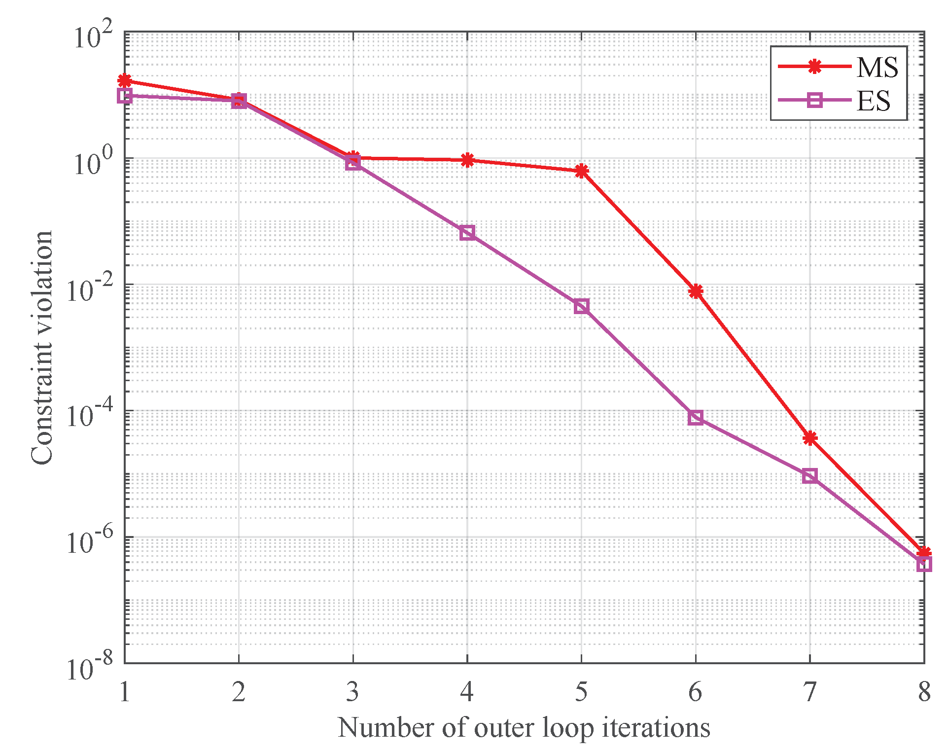
  • For the ES protocol, in contrast with conventional alternate optimization, which optimizes one variable every time, the proposed method can optimize all variables in all iterations. Successive convex approximation (SCA) and a penalty function are adopted to create a convex version of this non-convex issue. Then, the optimized results are obtained by updating the penalty factor in subsequent iterations.
  • The MS protocol is processed in a manner similar to the ES protocols. The key here is to deal with a binary constraint. We replace this binary constraint with a new penalty function. When the penalty factor increase to infinity, the modified problem is equal to the origin.
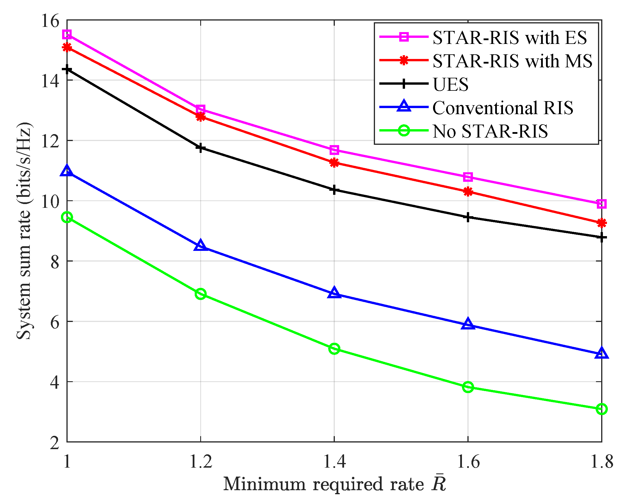
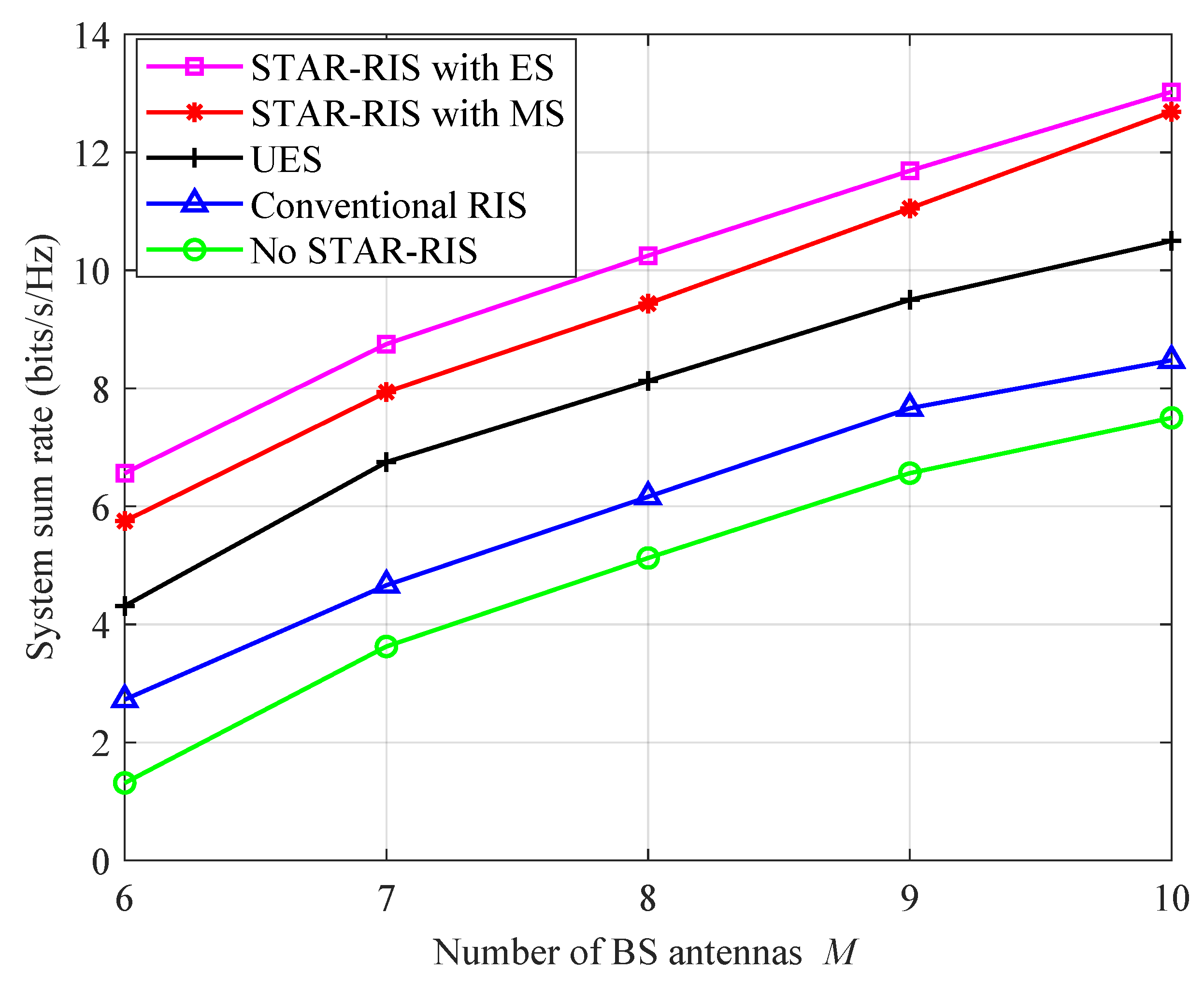
  • We evaluate the performance by comparing the system sum rate of proposed methods with three schemes: no RIS, conventional RIS, and uniform energy splitting. Through simulation and analysis, we reveal that the proposed system and methods have the highest system sum rate. In addition, the performance of the ES protocol is better than the MS protocol. However, the MS protocol is more easily implemented.
The rest of this paper is arranged as follows. In Section 2, the system model of the STAR-RIS-UAV-aided CoMP cellular system for multi-user networks is presented. Then, in Section 3, two penalty-function-based iterative methods are proposed. The complexity is analyzed in Section 4. In Section 5, simulations are shown to investigate the performance and convergence of our proposed methods. Finally, we draw conclusions in Section 6.

2. System Model

As shown in Figure 1, a CoMP cellular system with two adjacent cells is considered, and a STAR-RIS-UAV is employed to enhance the communications. This system uses CoMP transmission to mitigate inter-cell interference while using the STAR-RIS-UAV to generate a stronger channel gain at the cell edge user (CEU). Thus, this system could improve the performance of the CEU without affecting the performance of the cell center user (CCU). The STAR-RIS-UAV is hovered at the middle of the two cells to divide the whole system into two spaces; the CEU is located in the reflective half, while the CCU is situated in the refractive half. The BS owns M antennas, and the STAR-RIS has N elements. CEU and CCU are both single-antenna users. We, respectively, denote the channels from the BS to the STAR-RIS, CEU, and CCU as G k ( k = 1 , 2 ) C N × M , h k , E H C 1 × M , and  h k , C H C 1 × M . The channels from the STAR-RIS to the CEU and CCU are given by h R , E H C 1 × N and h R , k H C 1 × N . In addition, perfect CSIs are considered in this model.
For theES protocol, two modes are used by every component of the STAR-RIS. Typically, the energy of the received signal is divided with an energy splitting ratio, β n t : β n r , into the transmitted signal energy and the reflected signal energy. Thus, TARC matrices are, respectively, given by
Θ t ES = diag β 1 t e j θ 1 t , β 2 t e j θ 2 t , , β N t e j θ N t
and
Θ r ES = diag β 1 r e j θ 1 r , β 2 t e j θ 2 r , , β N t e j θ N r ,
where β n t , β n r [ 0 , 1 ] , β n t + β n r = 1 , and  θ n t , θ n r [ 0 , 2 π ) n N . A significant degree of design freedom for communication systems can be accomplished because the TARCs of each device can be optimized.
For the MS protocol, all elements of the STAR-RIS are separated into two categories. One category, which is in the transmission mode, owns N t elements. The other category has N r elements and works in the reflection mode, where N t + N r = N . In this case, the TARC matrices are given by
Θ t MS = diag β 1 t e j θ 1 t , β 2 t e j θ 2 t , , β N t e j θ N t
and
Θ r MS = diag β 1 r e j θ 1 r , β 2 r e j θ 2 r , , β N r e j θ N r ,
respectively, where β n t , β n r { 0 , 1 } , β n t + β n r = 1 , and  θ n t , θ n r [ 0 , 2 π ) , n N .
The MS protocol could be viewed as a unique instance of the ES protocol, where β n t = 0 or β n t = 1 . Obviously, MS has lower performance than ES, but it is more popular in practical applications due to its ease of implementation.
Let w k , E and w k , C denote the beamforming vector for the CEU and CCU and let s E and s k , C denote the information symbol transmitted to the CEU and CCU, respectively. It is assumed that E { | s E | 2 } = 1 and E { | s k , C | 2 } = 1 k . Then, the received signals at the CEU and CCU are, respectively, given by
y E = k = 1 2 ( h k , E H + h R , E H Θ t ES / MS G k ) ( w k , E s E + w k , C s k , C ) + n E
and
y k , C = ( h k , C H + h R , k H Θ r ES / MS G k ) ( w k , E s E + w k , C s k , C ) + n k , C ,
where n E CN ( 0 , σ E 2 ) and n k , C CN ( 0 , σ k , C 2 ) are the additive white Gaussian noises at the CEU and CCU, respectively. Let us define
v l = [ β 1 l e j θ 1 l , β 2 l e j θ 2 l , , β N l e j θ N l ] H C N × 1 , l t , r , u l = [ v l ; 1 ] F R , k = diag { h R , k H } , G k C N × M , F k = [ F R , k ; h k , C H ] , H R , k = diag { h R , E H } , G k C N × M , H R = [ H R , 1 , H R , 2 ] , h E = [ h 1 , E H , h 2 , E H ] H , H = [ H R ; h E H ] , w C = [ w 1 , C H , w 2 , C H ] H , w E = [ w 1 , E H , w 2 , E H ] H
for notational simplicity. Therefore, the achievable rate at the CEU and CCU for ES and MS are given by
R E = log 2 ( 1 + | u t H H w E | 2 | u t H H w C | 2 + σ E 2 )
and
R k , C = log 2 ( 1 + | u r H F k w k , C | 2 | u r H F k w k , E | 2 + σ k , C 2 ) ,
respectively. In this paper, in order to increase the sum rate of the STAR-RIS-assisted CoMP network [20], which is given by
k = 1 2 R k , C + R E ,
our goal is to jointly optimize the beamforming vectors and TARCs, subject to the transmit power constraints for the BSs, and the QoS constraint of the users.

3. Proposed Iterative Algorithm Employing a Penalty Function

In this section, two penalty-based iterative algorithms are proposed for the ES and MS protocols. Instead of employing the alternating optimization, we intend to optimize all optimization variables in each iteration. Then, the problem for MS could be solved by similar operations.

3.1. Joint Design of Beamforming Vector and STAR-RIS Coefficient Matrix for ES Protocol

Specifically, for the ES protocol, the problem can be written as
max w k , C , w k , E , u l k = 1 2 R k , C + R E
s . t . | | w k , C | | 2 + | | w k , E | | 2 P , k
R k , C R ¯ k , C , k
R E R ¯ E
[ u l ] n = β n l e j θ n l , θ n l [ 0 , 2 π ) , l , n
[ u l ] N + 1 = 1
β n l [ 0 , 1 ] , l β n l = 1 , l , n
where P denotes the maximum transmit powers for each BS, and R ¯ E and R ¯ k , C denote the minimum rate of the CEU and CCU, respectively. For the MS protocol, let us reformulate this equation by replacing β n l [ 0 , 1 ] with β n l [ 0 , 1 ] . Note that it is hard to achieve the globally optimal solution directly for the non-convex problem. Specifically, the constraints from Equations (11c) and (11d) are non-convex for the coupled optimization variables. Furthermore, for the conventional reflecting-only RIS, only one coefficient needs to be designed, while STAR-RIS require the joint optimization of the TARCs, which increases the difficulty of solving the optimization problem.
Firstly, let us deal with the issue of coupled optimization variables. Let us define W E = w E w E H , W C = w C w C H , W k , E = w k , E w k , E H , W k , C = w k , C w k , C H . Then, the SINR expressions in Equations (8) and (9) can be equivalently rewritten as
Γ E = Tr ( U t H W E H H ) Tr ( U t H W C H H ) + σ E 2
and
Γ k , C = Tr ( U r F k W k , C F k H ) Tr ( U F k W k , E F k H ) + σ k , C 2
By employing Equations (12) and (13), the optimization problem for ES is given by
min W k , C , W k , E , W C , W E , U l k = 1 2 log 2 ( 1 + Γ k , C ) log 2 ( 1 + Γ E )
s . t . Tr ( W k , C ) + Tr ( W k , E ) P , k γ k , C Tr ( U r F k W k , E F k H ) + γ k , C σ k , C 2
Tr ( U r F k W k , C F k H ) 0 , k γ E Tr ( U t H W C H H ) + γ E σ E 2
Tr ( U t H W E H H ) 0 ,
0 [ U l ] n , n 1 , [ U t ] n , n + [ U r ] n , n = 1 , l , n
[ U t ] N + 1 , N + 1 = [ U r ] N + 1 , N + 1 = 1
W C , W E 0 , W k , C , W k , E 0 , k ,
U l 0 , l rank ( W C ) = 1 , rank ( W C ) = 1 ,
rank ( W k , C ) = 1 , rank ( W k , E ) = 1 , k
rank ( U l ) = 1 , l
where γ E = 2 R ¯ E 1 and γ k , C = 2 R ¯ k , C 1 . Note that, since there are rank-one constraints and the coupling in SINR expressions, Equation (14) is still non-convex. To circumvent this obstacle, we can transform Equation (14a) into the following equivalent form:
k = 1 2 log 2 δ k k = 1 2 log 2 φ k + log 2 ψ log 2 ϕ ,
where δ k , φ k , ψ , ϕ are slack optimization variables. Afterwards, new constraints are added according to δ k , φ k , ψ , and ϕ , which are given by
δ k Tr ( U r F k W k , E F k H ) + σ k , C 2 ,
φ k Tr ( U r F k W k , C F k H ) + Tr ( U r F k W k , E F k H ) + σ k , C 2 ,
ψ Tr ( U t H W C H H ) + σ E 2 ,
and
ϕ Tr ( U t H W C H H ) + Tr ( U t H W E H H ) + σ E 2 ,
respectively. It can be seen that Equations (16)–(19) have a similar structure composed of a product of matrices. Then, we recast these equations in the form of the difference of the convex (DC) functions. For example, referring to Lemma 1 in [21], the first two terms in Equation (14c) can be converted into
γ k , C Tr ( U r F k W k , E F k H ) = γ k , C 2 | | U r + F k W k , E F k H | | F 2 γ k , C 2 | | U r | | F 2 γ k , C 2 | | F k W k , E F k H | | F 2
Tr ( U r F k W k , C F k H ) = 1 2 | | U r F k W k , C F k H | | F 2 1 2 | | U r | | F 2 1 2 | | F k W k , C F k H | | F 2
where the terms | | F k W k , E F k H | | F 2 , | | F k W k , C F k H | | F 2 and | | U r | | F 2 are concave with respect to W k , E , W k , C and U r , respectively, while the term | | U r + F k W k , E F k H | | F 2 is convex with respect to W k , E and U r , and the term | | U r F k W k , C F k H | | F 2 is convex with respect to W k , C and U r . Then, we apply the SCA approach in each iteration to construct a global lower bound on the terms by their first-order Taylor approximations, respectively, which are expressed as
| | U r | | F 2 | | U r ( t ) | | F 2 + 2 Tr ( U r ( t ) ) H U r ,
| | F k W k , E F k H | | F 2 | | F k W k , E ( t ) F k H | | F 2 + 2 Tr ( F k H F k W k , E ( t ) F k H F k ) H W k , E ,
and
| | F k W k , C F k H | | F 2 | | F k W k , C ( t ) F k H | | F 2 + 2 Tr ( F k H F k W k , C ( t ) F k H F k ) H W k , C ,
respectively, where U r ( t ) , W k , E ( t ) , and W k , C ( t ) are feasible points in the t-th iteration of the SCA. Hence, the non-convex constraint is replaced by
γ k , C 2 | | U r + F k W k , E F k H | | F 2 ( γ k , C + 1 ) Tr ( U r ( t ) ) U r + γ k , C + 1 2 | | U r ( t ) | | F 2 γ k , C Tr ( F k H F k W k , E ( t ) F k H F k ) H W k , E + γ k , C 2 | | F k W k , E ( t ) F k H | | F 2 + 1 2 | | U r F k W k , C F k H | | F 2 Tr ( F k H F k W k , C ( t ) F k H F k ) H W k , C + 1 2 | | F k W k , C ( t ) F k H | | F 2 + γ k , C σ k , C 2 0
Then, the constraint Equation (14d) can be dealt with by a similar method as Equation (14c). Therefore, the non-convex constraint is replaced by
γ E 2 | | U t + H W C H H | | F 2 ( γ E + 1 ) Tr ( U t ( t ) ) U t + γ E + 1 2 | | U t ( t ) | | F 2 γ E Tr ( H H H W C ( t ) H H H ) H W C + γ E 2 | | H W C ( t ) H H | | F 2 + 1 2 | | U t H W E H H | | F 2 Tr ( H H H W E ( t ) H H H ) H W E + 1 2 | | H W E ( t ) H H | | F 2 + γ E σ E 2 0
Similarly, the constraints Equations (16)–(19) are replaced by
1 2 | | U r + F k W k , E F k H | | F 2 Tr ( U r ( t ) ) U r + 1 2 | | U r ( t ) | | F 2 Tr ( F k H F k W k , E ( t ) F k H F k ) H W k , E + 1 2 | | F k W k , E ( t ) F k H | | F 2 + σ k , C 2 δ k 0 ,
1 2 | | U r F k W k , C F k H | | F 2 2 Tr ( U r ( t ) ) U r + | | U r ( t ) | | F 2 Tr ( F k H F k W k , C ( t ) F k H F k ) H W k , C + 1 2 | | F k W k , C ( t ) F k H | | F 2 + 1 2 | | U r F k W k , E F k H | | F 2 Tr ( F k H F k W k , E ( t ) F k H F k ) H W k , E + 1 2 | | F k W k , E ( t ) F k H | | F 2 + σ k , C 2 + φ k 0 ,
1 2 | | U t + H W C H H | | F 2 Tr ( U t ( t ) ) U t + 1 2 | | U t ( t ) | | F 2 Tr ( H H H W C ( t ) H H H ) H W C + 1 2 | | H W C ( t ) H H | | F 2 + σ E 2 ψ 0 ,
and
1 2 | | U t H W C H H | | F 2 2 Tr ( U t ( t ) ) U t + | | U t ( t ) | | F 2 Tr ( H H H W C ( t ) H H H ) H W C + 1 2 | | H W C ( t ) H H | | F 2 + 1 2 | | U t H W E H H | | F 2 Tr ( H H H W E ( t ) H H H ) H W E + 1 2 | | H W E ( t ) H H | | F 2 + σ E 2 + ϕ 0 ,
respectively. Next, we address the rank-one constraint, Equation (14j). The constraint Equation (14j) is able to be converted into
| | U l | | * | | U l | | 2 0 , l ,
where | | U l | | * = i σ i ( U l ) denotes the nuclear norm, and  | | U l | | 2 = max i σ i ( U l ) is the spectral norm. σ i ( U l ) is the i-th largest singular value of U l . Since the equality holds if and only if the rank-one constraint is satisfied, | | U l | | * | | U l | | 2 0 is always satisfied for any U l H M , U l 0 . Hence, for rank-one matrices U l , Equation (31) is met. Significantly, the constraint Equation (31) is still non-convex. Then, we adopt the penalty-based method to deal with this issue. By augmenting the constraint Equation (31) into the (14a), the objective function can be written as
min W k , C , W k , E , W C , W E , U l , δ k , φ k , ψ , ϕ f CU g CU + f CE g CE + χ l ( | | U l | | * | | U l | | 2 )
where f CU = k = 1 2 log 2 δ k , g CU = k = 1 2 log 2 φ k , f CE = log 2 ψ and g CE = log 2 ϕ . Constraints of (32) are (25)–(30) and (14e)–(14i).
Thus far, the constraint Equation (31) has become a penalty term in Equation (32), and  χ > 0 denotes a penalty factor for any U l whose rank is not one. When χ + , the problems Equations (14) and (32) are identical. The initial value of χ should be small because a large χ could result in a negligible effect of the sum rate in Equation (32). Then, gthe value of χ is gradually increased to meet the rank-one constraint. However, since Equation (32) is non-convex and there are non-convex constraints, Equation (32) is still non-convex.
Based on the proposed transformations, the objective function is also in the form of DC. To handle the non-convex objective function, for any feasible points δ k ( t ) and ψ ( t ) in the t-th iteration of SCA, the global lower bounds of f CU and f CE can be obtained by using first-order Taylor expansion, as follows:
f CU k = 1 2 ( log 2 δ k ( t ) + δ k δ k ( t ) ln 2 δ k ( t ) ) f ¯ CU ( δ k , δ k ( t ) ) ,
f CE log 2 ψ ( t ) + ψ ψ ( t ) ln 2 ψ ( t ) f ¯ CE ( ψ , ψ ( t ) ) ,
Similarly, for any feasible points U l ( t ) in the t-th iteration, we have
| | U l | | * | | U l | | 2 | | U l | | * U ¯ l ( t )
where
U ¯ l ( t ) | | U ¯ l ( t ) | | 2 + Tr λ ( U l ( t ) ) ( λ ( U l ( t ) ) ) H ( U l U l ( t )
λ ( U l ( t ) ) is the eigenvector corresponding to the maximum eigenvalue of U l ( t ) . Then, Equation (32) is replaced by
min W k , C , W k , E , W C , W E , U l , δ k , φ k , ψ , ϕ f ¯ CU g CU + f ¯ CE g CE + χ l ( | | U l | | * U ¯ l ( t ) )
Constraints of (37) are (25)–(30) and (14e)–(14i).
Here, the only non-convexity of Equation (37) lies in the rank-one constraint equations, and this constraint can be omitted using semi-definite relaxation (SDR) to solve the relaxation problem. The issue can thus be converted into a standard convex SDP problem, which can be solved directly using CVX [27]. Then, an iterative algorithm based on the penalty function is proposed for solving the problem, which consists of two loops. χ is gradually increased during each iteration in the outer loop according to χ = ω χ , where ω > 1 . The outer loop will be terminated when the following criterion is met:
max | | U l | | * | | U l | | 2 , l { t , r } ε 1
where ε 1 is the threshold set by Equation (31). Therefore, as  χ increases, the constraint Equation (31) will eventually satisfy the accuracy ε 1 . In the inner loop, the variables will be continuously optimized by solving the relaxation problem Equation (37) with a fixed penalty factor. In the inner loop, Equation (37a) is non-increasing, and it has a lower bound. Therefore, the proposed penalty-based iterative method will converge to a stable point when χ approaches infinity. The details are shown in Algorithm 1.
Algorithm 1: Proposed penalty-based based iterative method for ES protocol.
Drones 07 00403 i001

3.2. Joint Design of Beamforming Vector and STAR-RIS Coefficient Matrix for MS Protocol

Now that we have solved the optimization problem in the ES mode, this subsection proceeds to study the maximum sum rate problem in the MS protocol, where the magnitude coefficients of STAR-RIS can only be chosen to be between 0 and 1. Therefore, the optimization problem on the STAR-RIS coefficients becomes a 0–1 integer programming problem, which can be given by
max w k , C , w k , E , u l k = 1 2 R k , C + R E
s . t . | | w k , C | | 2 + | | w k , E | | 2 P , k
R k , C R ¯ k , C , k
R E R ¯ E
[ u l ] n = β n l e j θ n l , θ n l [ 0 , 2 π ) , l , n
[ u l ] N + 1 = 1
β n l { 0 , 1 } , l , n
Compared with the ES protocol, this optimization problem involves an additional non-convex binary constraint, β n l { 0 , 1 } , in the MS protocol. Since other non-convex items can be handled in a similar way as in the previous subsection, it is only necessary to focus on how to solve this new binary constraint. This binary constraint can be transferred into an equation constraint as follows:
β n l ( β n l ) 2 = 0 , l , n
because β n l { 0 , 1 } , β n l ( β n l ) 2 0 is always satisfied and the equality holds if and only if β n l = 0 or β n l = 1 . Thus, Equation (40) is satisfied when β n l = 0 or β n l = 1 .
In the following, we will investigate how to extend the penalty-based iterative algorithm proposed in the ES protocol to the optimization problem in the MS protocol. Based on the method for the ES protocol, Equation (40) can be added to the objective function as an additional penalty term. Thus, Equation (39a) can be transformed into
min W k , C , W k , E , W C , W E , U l , δ k , φ k , ψ , ϕ f ¯ CU g CU + f ¯ CE g CE + χ l ( | | U l | | * U ¯ l ( t ) ) + η n = 1 N l β n l ( β n l ) 2
where η > 0 denotes a new penalty factor. When χ , η + , the solution of Equation (41) is able to satisfy Equations (31) and (40). Constraints of (41) are (25)–(30) and (14e)–(14i). Then, the SCA can still be adopted to solve this non-convex optimization problem. For a given { β l ( t ) } , the upper bound can be achieved using the first-order Taylor approximation,
β n l ( β n l ) 2 β n l ( β n l ( t ) ) 2 2 β n l ( t ) β n l β n l ( t ) = 1 2 β n l ( t ) β n l + β n l ( t ) 2 Ω β n l , β n l ( t ) , l , n
Substituting Equation (42) into Equation (41), we have
min W k , C , W k , E , W C , W E , U l , δ k , φ k , ψ , ϕ f ¯ CU g CU + f ¯ CE g CE + χ l ( | | U l | | * U ¯ l ( t ) ) + η n = 1 N l Ω β n l , β n l ( t )
Constraints of (41) are (25)–(30) and (14e)–(14i).
Then, SDR is used again to remove the non-convex rank-one constraint, and Equation (43) is also convex and is able to be solved directly with CVX [27]. Similar to the ES protocol, the two-level cyclic penalty-based iterative algorithm is able to be employed for the optimization problem in the MS protocol. Since there are two penalty factors in Equation (43), the algorithm terminates when the following criterion is satisfied:
max | | U l | | * | | U l | | 2 β n l ( β n l ) 2 ε 2 , l { t , r }
where ε 2 is a maximum violation of constraint Equation (31) and (42). The specific steps of the algorithm are summarized as Algorithm 2:
Algorithm 2: Proposed penalty-based iterative method for ES protocol.
Drones 07 00403 i002

4. Computational Complexity

Next, we investigate the computational complexity of the proposed methods. The main complexity lies in solving the SDR after relaxation, and since the relaxation problem is an SDP problem, the computational complexity for each iteration is given by
C s = O K M 6.5 + 2 N 6.5
Therefore, the total computational complexity of the proposed method can be expressed by
C p = O I o u t I i n K M 6.5 + 2 N 6.5
where I o u t and I i n are the number of iterations for the inner and outer loops. It can be seen that the computational complexity of this method is a polynomial over N. Thus, even if the number of elements of STAR-RIS is too large, the algorithm still has a relatively low computational complexity. In addition, we can optimize the problem by employing alternating optimization, as many works have [7,15,17]. In each iteration, there are two SDR problems for optimizing W k , C and W k , E , respectively. Thus, the computational complexity for each iteration will increase to O 2 K M 6.5 + 2 N 6.5 . The total computational complexity is given by O I o u t I i n 2 K M 6.5 + 2 N 6.5 , which is higher than the proposed penalty-based methods. Thus, it is easier to implement the proposed methods in practical applications.

5. Simulation Results and Analysis

In this section, the performance of the STAR-RIS-UAV-aided CoMP system is simulated and verified. Consider a 3D coordinate system, where 2 BSs were located at (0 m, 0 m, 10 m) and (140 m, 0 m, 10 m), respectively, with the radius of each cell set to 80 m. STAR-RIS-UAV was located in the overlapping area of the two cells, set at (70 m, 20 m, 20 m). CCU1 and CCU2 were located in the reflection half of the STAR-RIS and were randomly distributed in the two discs centered on the adjacent BS with inner and outer diameters of 20 m and 40 m, respectively. The CEU was randomly distributed in the overlapping area of the two cells and was located in the transmission half of the area 20 m away from the STAR-RIS. The path loss was calculated as P L = P L 0 ( d / d 0 ) α , where P L 0 = 10 3 was the channel gain when d 0 = 1 m, d denotes the path distance, and α = 2.2 is the path loss index. In the simulation, all channel models used the Rice fading channel, and the channel is given by
G = ρ ρ + 1 G L O S + 1 ρ + 1 G N L O S
where ρ = 5 dB is the Rice coefficient. G L O S denotes the LOS component of the channel, obtained by multiplying the transmit and receive direction vectors. As modeled by Rayleigh fading, G N L O S is the NLOS component. Given that the maximum transmitting power of the two BSs was the same and the minimum required rate R ¯ k , C and R ¯ E were equal, R ¯ k , C = R ¯ E . The noise variance was set as σ k , C 2 = σ E 2 = 90 dBm. In addition, ε 1 = ε 2 = 10 7 and the initial values of the penalty factors χ and η were set as 10 7 .
In order to better investigate the advantages of STAR-RIS in the corresponding ES and MS protocols, three comparison schemes were proposed, as follows:
  • Conventional RIS: Instead of using STAR-RIS, full coverage was achieved by two reflective-only RISs. The two RISs were adjacent to each other and deployed at the same locations. For a fair comparison, it was assumed that each conventional reflection/transmission RIS had N / 2 elements; this number was set to be even for simplicity.
  • Uniform energy splitting (UES): It was assumed that the TARCs of all components of STAR-RIS in ES mode were equal, β n t = β ¯ n t , β n r = β ¯ n r , n , where 0 β ¯ n t , β ¯ n r 1 , β ¯ n t + β ¯ n r = 1 . UES can be viewed as a specific example of STAR-RIS with a group/face amplitude design in ES protocol.
  • No STAR-RIS: Without the aid of STAR-RIS, the system becomes a traditional collaborative multi-point transmission communication system.
The constraint violations over the number of iterations in the outer loop for ES and MS protocols are shown in Figure 2. From Figure 2, it can be seen that the constraint violations decrease rapidly for both ES and MS as the number of iterations increases and eventually satisfy the predetermined accuracy (i.e., ε 1 = ε 2 = 10 7 ) after 8 iterations. In other words, the TARC matrices { U l } , as well as the binary TARCs { β n l } , were optimized by the penalty-based iterative algorithm after 8 iterations.
Figure 3 shows a graph of the variations of the system sum rate versus the maximum transmit power. It can be seen that the system sum rate of all schemes increases monotonically with increases in the maximum transmit power. In addition, the ES mode obtains a higher system sum rate than the MS and UES schemes because the ES mode has a freer choice of amplitude and phase shift, while the MS and UES schemes have certain restrictions on the TARCs. the amplitude coefficients in MS can only be chosen from 0 and 1, while UES requires equal amplitude coefficients for all components. Therefore, the ES mode allows better adjustment of each element’s phase shift and amplitude coefficients, making full use of the degrees of freedom obtained by each element boost. From the mathematical and optimization point of view, both the MS mode and the UES scheme are a special case of the ES mode. In addition, for conventional RIS schemes, since only a fixed number of RIS elements perform a single reflection or transmission function, while STAR-RIS can flexibly control the number of elements involved in transmission and reflection, STAR-RIS can provide a greater degree of freedom than conventional RIS to enhance the signal strength. In particular, when compared with the ES and MS protocols, conventional RIS schemes suffer some performance loss. In addition, it is obvious that the performance of the STAR-free RIS is the worst among these schemes. Through the effective combination of the STAR-RIS and collaborative multipoint methods, passive beamforming can be reasonably designed with STAR-RIS to enhance the combined channel gain at CEU and eliminate the adverse effects of inter-cell interference, thus further improving the system’s performance.
Figure 4 depicts the variation of the system sum rate over the number of STAR-RIS elements. From this figure, it can be observed that only the system sum rate of the no-STAR-RIS scheme remains constant, while the system sum rate of all the remaining schemes increases with the increase of the number of STAR-RIS elements. This is due to the fact that more signal energy can reach the STAR-RIS when the number of STAR-RIS elements increases, so that the STAR-RIS could use more elements to control the energy and phase of the incident signal and optimize the TARC of each element rationally, thus increasing the system sum rate. Installing more elements also provides more freedom in resource allocation, which facilitates higher beamforming gain and thus higher sum rate. In addition, since the elements are passive, low power consumption and low cost, STAR-RIS with hundreds or even thousands of elements is expected to be used. it can also be seen from the figure that the performance of ES mode and MS is still better than other comparison schemes, once again proving the superiority of STAR-RIS.
Figure 5 plots the system sum rate over the variation in the minimum required rate. As observed in Figure 5, the system sum rate decreases monotonically as the minimum required rate of the user increases. In particular, when the user’s channel conditions are poor, the increase in the minimum required rate causes the system to be forced to allocate more resources to it, reducing the flexibility of the communication system’s resource allocation. In addition, compared with the no-STAR-RIS scheme, the system rate and the decreasing seen in it with increases in the minimum required rate are relatively slow in the scheme with STAR-RIS as well as the conventional RIS assistance. This is because the deployment of RIS can mitigate the effect of interference in the system, and without the assistance of STAR-RIS, the reflected signal cannot accurately reach the subscriber side to promote effective beamforming. The system is more sensitive to minimum rate requirements, and the additional degrees of freedom brought by collaborative multipoint techniques cannot be fully used to solve the inter-cell interference problem. Similar to the results in Figure 4 and Figure 5, the ES and MS modes with STAR-RIS still achieve the best performance, highlighting the importance of STAR-RIS as an aid to collaborative multipoint transmission systems.
Figure 6 shows the variation of the system sum rate versus the number of BS antennas. From the figure, it is clear that when the number of BS antennas rises, the system sum rate grows as well. This is because more BS antennas can obtain higher beamforming gain, which improves the performance of the system. At the same time, the ES and MS modes still outperform the other comparison schemes because STAR-RIS deploys a variable number of transmitting and reflecting elements, making use of the degrees of freedom in the system to enhance the signal strength.

6. Conclusions

In this work, to maximize the system sum rate under the maximum transmit power constraint of the BS as well as the minimum rate constraint of the users, we jointly designed a BS transmit beamforming method and TARCs matrices of the STAR-RIS method for STAR-RIS-UAV-aided CoMP systems. Furthermore, to effectively solve the non-convex optimization problem in both protocols, an iterative algorithm based on a penalty function was proposed for the ES protocol and further extended to the MS protocol. The simulation results proved that STAR-RIS-UAV is able to significantly increase the system sum rate compared with the conventional RIS scheme as well as the no-STAR-RIS scheme. More importantly, our proposed method can also be used when the system serves other UAVs. This conclusion provides useful guidance for STAR-RIS-UAV-aided CoMP systems. More importantly, our methods can also be used in UAV communications when the BS is replaced by a UAV. However, when our structure and method are employed in multi-UAV networks, UAVs will keep moving. Thus, the trajectories of drones may affect the sum rate. To deal with this problem, it is necessary to optimize the trajectories of the drones and the coefficients of STAR-RIS at the same time. This will become our future work. In general, our proposed system and methods are promising for use in practical applications.

Author Contributions

Conceptualization, B.S.; methodology, B.S.; software, Y.W.; validation, B.S. and Y.W.; formal analysis, W.S.; investigation, S.Y., W.C., J.L., S.Z. and W.S.; resources, D.L., S.Y. and F.S.; data curation, F.S.; writing—original draft preparation, B.S.; writing—review and editing, D.L. and Y.W.; visualization, W.S.; supervision, F.S.; project administration, F.S.; funding acquisition, F.S. All authors have read and agreed to the published version of the manuscript.

Funding

This work was supported in part by the National Natural Science Foundation of China (Nos.U22A2002, 61972093 and 62071234), the Hainan Province Science and Technology Special Fund (ZDKJ2021022), and the Scientific Research Fund Project of Hainan University under Grant KYQD(ZR)-21008.

Informed Consent Statement

Not applicable.

Data Availability Statement

Not applicable.

Conflicts of Interest

The authors declare no conflict of interest.

Abbreviations

The following abbreviations are used in this manuscript:
6GSixth-generation communication network
UAVUnmanned aerial vehicle
RISReconfigurable intelligent surface
STAR-RISSimultaneous transmitting and reflecting RIS
ESEnergy splitting
MSMode switching
TSTime switching
TARCTransmitted and reflected coefficients
CoMPCoordinated multipoint
MIMOMultiple-input multiple-output
2DTwo dimensional
QoSQuality-of-service
LOSLine-of-sight
BSBase station
CEUCell edge user
CCUCell center user
SCASuccessive convex approximation
SDRSemi-definite relaxation
UESUniform energy splitting

References

  1. Huang, C.; Zappone, A.; Alexandropoulos, G.C.; Debbah, M.; Yuen, C. Reconfigurable Intelligent Surfaces for Energy Efficiency in Wireless Communication. IEEE Trans. Wirel. Commun. 2019, 18, 4157–4170. [Google Scholar] [CrossRef] [Green Version]
  2. Wu, Q.; Zhang, R. Towards Smart and Reconfigurable Environment: Intelligent Reflecting Surface Aided Wireless Network. IEEE Commun. Mag. 2020, 58, 106–112. [Google Scholar] [CrossRef] [Green Version]
  3. Liu, Y.; Liu, X.; Mu, X.; Hou, T.; Xu, J.; Di Renzo, M.; Al-Dhahir, N. Reconfigurable Intelligent Surfaces: Principles and Opportunities. IEEE Commun. Surv. Tuts. 2021, 23, 1546–1577. [Google Scholar] [CrossRef]
  4. Pan, C.; Ren, H.; Wang, K.; Elkashlan, M.; Nallanathan, A.; Wang, J.; Hanzo, L. Intelligent Reflecting Surface Aided MIMO Broadcasting for Simultaneous Wireless Information and Power Transfer. IEEE J. Sel. Areas Commun. 2020, 38, 1719–1734. [Google Scholar] [CrossRef]
  5. Wu, Q.; Zhang, R. Joint Active and Passive Beamforming Optimization for Intelligent Reflecting Surface Assisted SWIPT Under QoS Constraints. IEEE J. Sel. Areas Commun. 2020, 38, 1735–1748. [Google Scholar] [CrossRef]
  6. Cui, M.; Zhang, G.; Zhang, R. Secure Wireless Communication via Intelligent Reflecting Surface. IEEE Wirel. Commun. Lett. 2019, 8, 1410–1414. [Google Scholar] [CrossRef] [Green Version]
  7. Shi, W.; Wu, Q.; Xiao, F.; Shu, F.; Wang, J. Secrecy Throughput Maximization for IRS-Aided MIMO Wireless Powered Communication Networks. IEEE Trans. Commun. 2022, 70, 7520–7535. [Google Scholar] [CrossRef]
  8. Yue, X.; Xie, J.; Liu, Y.; Han, Z.; Liu, R.; Ding, Z. Simultaneously Transmitting and Reflecting Reconfigurable Intelligent Surface Assisted NOMA Networks. IEEE Trans. Wirel. Commun. 2023, 22, 189–204. [Google Scholar] [CrossRef]
  9. Khaleel, A.; Basar, E. A Novel NOMA Solution with RIS Partitioning. IEEE J. Sel. Topics Signal Process. 2022, 16, 70–81. [Google Scholar] [CrossRef]
  10. Zhi, K.; Pan, C.; Ren, H.; Wang, K.; Elkashlan, M.; Renzo, M.D.; Schober, R.; Poor, H.V.; Wang, J.; Hanzo, L. Two-Timescale Design for Reconfigurable Intelligent Surface-Aided Massive MIMO Systems with Imperfect CSI. IEEE Trans. Inf. Theory 2023, 69, 3001–3033. [Google Scholar] [CrossRef]
  11. Ren, H.; Wang, K.; Pan, C. Intelligent Reflecting Surface-Aided URLLC in a Factory Automation Scenario. IEEE Trans. Commun. 2022, 70, 707–723. [Google Scholar] [CrossRef]
  12. Li, S.; Duo, B.; Yuan, X.; Liang, Y.C.; Di Renzo, M. Reconfigurable Intelligent Surface Assisted UAV Communication: Joint Trajectory Design and Passive Beamforming. IEEE Wirel. Commun. Lett. 2020, 9, 716–720. [Google Scholar] [CrossRef] [Green Version]
  13. Mu, X.; Liu, Y.; Guo, L.; Lin, J.; Poor, H.V. Intelligent Reflecting Surface Enhanced Multi-UAV NOMA Networks. IEEE J. Sel. Areas Commun. 2021, 39, 3051–3066. [Google Scholar] [CrossRef]
  14. Ren, H.; Zhang, Z.; Peng, Z.; Li, L.; Pan, C. Energy Minimization in RIS-Assisted UAV-Enabled Wireless Power Transfer Systems. IEEE Internet Things J. 2023, 10, 5794–5809. [Google Scholar] [CrossRef]
  15. Wu, Q.; Zhang, R. Intelligent Reflecting Surface Enhanced Wireless Network via Joint Active and Passive Beamforming. IEEE Trans. Wirel. Commun. 2019, 18, 5394–5409. [Google Scholar] [CrossRef] [Green Version]
  16. Hong, S.; Pan, C.; Ren, H.; Wang, K.; Nallanathan, A. Artificial-Noise-Aided Secure MIMO Wireless Communications via Intelligent Reflecting Surface. IEEE Trans. Commun. 2020, 68, 7851–7866. [Google Scholar] [CrossRef]
  17. Shi, W.; Zhou, X.; Jia, L.; Wu, Y.; Shu, F.; Wang, J. Enhanced Secure Wireless Information and Power Transfer via Intelligent Reflecting Surface. IEEE Commun. Lett. 2021, 25, 1084–1088. [Google Scholar] [CrossRef]
  18. Shu, F.; Teng, Y.; Li, J.; Huang, M.; Shi, W.; Li, J.; Wu, Y.; Wang, J. Enhanced Secrecy Rate Maximization for Directional Modulation Networks via IRS. IEEE Trans. Commun. 2021, 69, 8388–8401. [Google Scholar] [CrossRef]
  19. Dong, R.; Teng, Y.; Sun, Z.; Zou, J.; Huang, M.; Li, J.; Shu, F.; Wang, J. Performance analysis of wireless network aided by discrete-phase-shifter IRS. J. Commun. Netw. 2022, 24, 603–612. [Google Scholar] [CrossRef]
  20. Niu, H.; Chu, Z.; Zhou, F.; Xiao, P.; Al-Dhahir, N. Weighted Sum Rate Optimization for STAR-RIS-Assisted MIMO System. IEEE Trans. Veh. Technol. 2022, 71, 2122–2127. [Google Scholar] [CrossRef]
  21. Mu, X.; Liu, Y.; Guo, L.; Lin, J.; Schober, R. Simultaneously Transmitting and Reflecting (STAR) RIS Aided Wireless Communications. IEEE Trans. Wirel. Commun. 2022, 21, 3083–3098. [Google Scholar] [CrossRef]
  22. Gao, Q.; Liu, Y.; Mu, X.; Jia, M.; Li, D.; Hanzo, L. Joint Location and Beamforming Design for STAR-RIS Assisted NOMA Systems. IEEE Trans. Commun. 2023, 71, 2532–2546. [Google Scholar] [CrossRef]
  23. Zhai, X.; Han, G.; Cai, Y.; Liu, Y.; Hanzo, L. Simultaneously Transmitting and Reflecting (STAR) RIS Assisted Over-the-Air Computation Systems. IEEE Trans. Commun. 2023, 71, 1309–1322. [Google Scholar] [CrossRef]
  24. Irmer, R.; Droste, H.; Marsch, P.; Grieger, M.; Fettweis, G.; Brueck, S.; Mayer, H.P.; Thiele, L.; Jungnickel, V. Coordinated multipoint: Concepts, performance, and field trial results. IEEE Commun. Mag. 2011, 49, 102–111. [Google Scholar] [CrossRef] [Green Version]
  25. Hua, M.; Wu, Q.; Ng, D.W.K.; Zhao, J.; Yang, L. Intelligent Reflecting Surface-Aided Joint Processing Coordinated Multipoint Transmission. IEEE Trans. Commun. 2021, 69, 1650–1665. [Google Scholar] [CrossRef]
  26. Xie, H.; Xu, J.; Liu, Y.F. Max-Min Fairness in IRS-Aided Multi-Cell MISO Systems With Joint Transmit and Reflective Beamforming. IEEE Trans. Wirel. Commun. 2021, 20, 1379–1393. [Google Scholar] [CrossRef]
  27. Grant, M.; Boyd, S.; Ye, Y. CVX: Matlab Software for Disciplined Convex Programming, Version 2.0 Beta. Available online: http://cvxr.com/cvx (accessed on 25 May 2023).
Figure 1. System model.
Drones 07 00403 g001
Figure 2. Constraint violation over the number of outer loop iterations.
Drones 07 00403 g002
Figure 3. System sum rate versus the maximum transmit power.
Drones 07 00403 g003
Figure 4. System sum rate versus the number of elements.
Drones 07 00403 g004
Figure 5. System sum rate over the minimum required rate.
Drones 07 00403 g005
Figure 6. System sum rate over the number of BS antennas.
Drones 07 00403 g006
Disclaimer/Publisher’s Note: The statements, opinions and data contained in all publications are solely those of the individual author(s) and contributor(s) and not of MDPI and/or the editor(s). MDPI and/or the editor(s) disclaim responsibility for any injury to people or property resulting from any ideas, methods, instructions or products referred to in the content.

