Article

Disturbance Observer-Enhanced Adaptive Fault-Tolerant Control of a Quadrotor UAV against Actuator Faults and Disturbances

1
School of Aeronautics, Northwestern Polytechnical University, Xi’an 710072, China
2
Department of Electrical and Computer Engineering, Concordia University, Montreal, QC H3G 1M8, Canada
*
Author to whom correspondence should be addressed.
Drones 2023, 7(8), 541; https://doi.org/10.3390/drones7080541
Submission received: 22 July 2023 / Revised: 15 August 2023 / Accepted: 18 August 2023 / Published: 21 August 2023

Abstract

:
For a quadrotor unmanned aerial vehicle (UAV), this paper proposes an adaptive sliding mode control (SMC) strategy enhanced with a disturbance observer to attain precise trajectory and attitude tracking performance while compensating for the detrimental impacts of actuator faults and disturbances. First, an adaptive SMC strategy that utilizes an integral sliding surface is presented to enhance the fault-tolerance capabilities of the studied quadrotor UAV against actuator faults. In addition, a disturbance observer is further created to compensate for the disturbances. By integrating the proposed adaptive SMC strategy with the designed disturbance observer, both actuator faults and disturbances can be effectively accommodated. It was theoretically demonstrated that the system is stable while using the proposed adaptive fault-tolerant control strategy. The effectiveness and benefits of the proposed strategy is verified with comparative simulation results under different faulty scenarios.

1. Introduction

As a result of the rapid advancement of novel materials, micro-inertial-measurement units, flight control technology and integrated circuits, the cost of quadrotor unmanned aerial vehicles (UAVs) has been considerably lowered. Because of its straightforward construction for simple operation and high maneuverability, quadrotor UAVs have served a number of missions in both military and commercial sectors. Quadrotor UAVs can not only be used for a variety of tasks for communication relay [1] and battlefield reconnaissance [2] but can also play an important role in logistics transportation [3], forest fire surveillance [4], precision agriculture [5], power line inspection [6] and 3D mapping [7]. The capability to conduct stable attitude control and accurate trajectory tracking is a prerequisite for quadrotor UAVs to carry out the aforementioned missions. Thus, it is crucially essential to create the attitude and trajectory system of quadrotor UAVs. A quadrotor UAV is basically a highly coupled and nonlinear system that is also vulnerable to disturbances in practical applications, for example, environmental disturbances and actuator faults. This calls for reliable flight control systems for quadrotor UAVs that will ensure the safety of both the quadrotor UAVs and the surrounding human life and property under various uncertain conditions. In terms of the UAV attitude control technologies, feedback linearization control [8], sliding mode control (SMC) [9] and backstepping control [10] are the three major categories of robust control methods used for quadrotor UAVs. Furthermore, it is indicated in [11] that favorable disturbance rejection and tracking precision can be achieved by employing the aforementioned methods. In [12], two different hybrid control schemes consisting of SMC and backstepping are reviewed that can enhance the robustness of the designed control schemes for quadrotor UAVs. In [13], the performance of flight control systems is effectively improved by utilizing the combination of disturbance observers and nonlinear control methods. In [14], a flight control system based on the feedback linearization technique can achieve precise attitude and altitude control in spite of parameter uncertainties and wind gust disturbances. In [15], a sliding mode attitude controller with excellent attitude tracking precision and robustness is designed for a time-varying mass quadrotor UAV containing disturbances. In [16], a control system of quadrotor UAV is constructed by combining the backstepping method with an adaptive technique, and the system is constructed to keep favorable tracking performance with input saturation.
In order to reach the aim of the safe control of quadrotor UAVs, the different influencing factors encountered during flight are also worth paying attention to and researching. In reality, actuator faults are the primary uncertainty that may affect the performance and stability of quadrotor UAVs. Actuator faults can be detected and identified by using a fault detection and diagnosis (FDD) module. The FDD module by itself, however, is insufficient to guarantee the safety of the quadrotor UAV. As a result, researchers have focused on fault-tolerant control (FTC) and have performed an extensive and in-depth study on it. A summary of the current advancements in FDD and FTC technology for UAVs is provided in [17]. The two sorts of FTC systems are active fault-tolerant control systems (AFTCS) and passive fault-tolerant control systems (PFTCS). In AFTCS, the onboard controller is modified in accordance with information supplied by the FDD module [18]. On the contrary, the PFTCS is intended to maintain the complete system running smoothly and safely through its robust design [19]. In [20], the robust control approach is created for fault compensation, where actuator faults can be treated as the model uncertainty. SMC is a robust control strategy that is simultaneously effective and practical. Due to the fact that SMC is insensitive to changes in parameters and system disturbances, the primary benefit of SMC is that it is not necessary for an system model. In [21], fuzzy logic control, SMC and a neural network are combined to create a fault-tolerant control scheme that has the benefits of lowering system chattering and minimizing the amount of fuzzy control rules while ensuring the system’s stability and robustness. In the event of model uncertainties, precise position tracking and stable attitude control are possible with a combination of recursive control and SMC [22]. The addition of twisting methods into the control law also guarantees quick and accurate system reaction and eliminates control chattering [23,24]. Moreover, second-order SMC [25], cascaded SMC [19] and iterative learning SMC [26] are able to operate quadrotor UAVs precisely and avoid control chattering.
Adaptive sliding mode control (ASMC) is another effective solution to suppress system chattering caused by large discontinuous control gains [27,28,29,30,31,32,33,34]. Uncertainties induced by modeling errors, external disturbances and actuator faults are frequently dealt with by estimating and compensating for the load mass, moment of inertia or control effect matrix in ASMC. In [35], the adaptive terms can compensate for the uncertainties and disturbances. In [36], the adaptive speed of the control law is accelerated by estimating the switching gain. In [37,38], a universal adaptive control law is proposed that estimates multiple UAV parameters and employs a parallel structure to guarantee the controller’s robustness. By incorporating adaptive sliding mode control methods into attitude control, the adverse effect caused by model uncertainties of the quadrotor UAV can be successfully eliminated [39]. During operation, quadrotor UAVs are susceptible to external disturbances, and control methods incorporating disturbance observers can enhance the system’s robustness [40,41,42,43,44,45,46]. Researchers are interested in the sliding mode observer because an exact model is not required [47]. In [48,49], a multivariable and multiple-loop SMC driven by the observer is created to accomplish the target of the accurate control of quadrotor UAVs with disturbances. In [50,51,52], different artificial intelligence approaches are applied to develop the performance of the system and strengthen its reliability and robustness.
Although there are many research works on the attitude control and trajectory tracking of quadrotor UAVs when considering actuator faults and disturbances, some problems still exist:
  • The existing ASMC methods usually adaptively modify the gain of the discontinuous control part while ignoring the continuous part, which may result in system control chattering due to parameter overestimation.
  • In addition, the existing adaptive schemes are commonly constructed with a sliding variable, if the system tracking error is not zero in practical applications, the adaptation does not cease, which also causes parameter overestimation.
  • The majority of the existing fault-tolerant control techniques depend on the robustness of the designed controller to accommodate the adverse effects of the external disturbances. However, when the encountered disturbances are significantly large, it may cause instability in the system.
Inspired by the aforementioned problems, this paper proposes an ASMC strategy enhanced with a observer for a quadrotor UAV to achieve the desired tracking performance against actuator faults and disturbances. The following summarizes the major contributions of this paper:
  • The proposed control approach does not merely rely on the robustness of SMC, and it can also adaptively create control signals to compensate for actuator faults and disturbances. The proposed method can alter the gain of both the continuous and discontinuous control sections while decreasing the system control chattering caused by the overuse of the discontinuous control gain.
  • The proposed adaptive control approach is formulated with the sliding variable and the boundary layer thickness, which can avoid overestimation of the control parameters, compared to the existing adaptive control schemes in the literature, where the adaptive control is commonly constructed merely with a sliding variable. The adaptation can be stopped using the proposed approach as long as the sliding variable is contained inside the boundary layer.
  • A sliding mode observer is proposed and integrated with the designed ASMC scheme to actively compensate both actuator faults and disturbances. It can further contribute to decreasing the value of the discontinuous control gain and suppress the unexpected control chattering.
The remaining sections of this paper are organized as follows. In Section 2, the modeling of the studied quadrotor UAV is constructed. The complete design of the proposed fault-tolerant control method is detailed in Section 3. Computer simulations are carried out in Section 4 to confirm the superiority of the method. Finally, the conclusion is provided in Section 5.

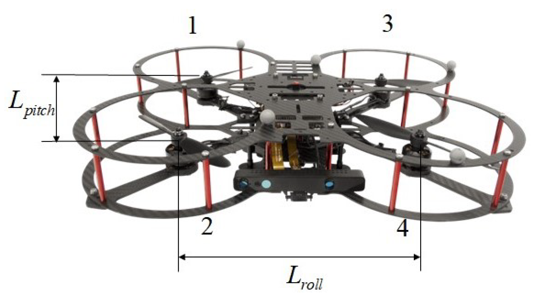
2. Modeling of the Quadrotor UAV

The detailed modeling of the studied quadrotor UAV, as shown in Figure 1, is described in this section. The parameters of the studied quadrotor UAV are provided in Table 1. First, assume that all of the rotation axes of the propellers are fixed to the body-fixed reference frame and parallel to each other. The actuator # i ( i = 1 , 2 , 3 , 4 ) are labeled in Figure 1 and Figure 2. To model the studied quadrotor UAV, two reference frames are defined, as shown in Figure 2, i.e., the body-fixed reference frame ( O b , X b , Y b , Z b ) and the earth-fixed reference frame ( O e , X e , Y e , Z e ) . The position vector Ω = [ x , y , z ] T and attitude vector Θ = [ ϕ , θ , ψ ] T are defined in the earth-fixed reference frame. The velocity vector [ u , v , w ] T and angular velocity vector [ p , q , r ] T are defined in the body-fixed reference frame.
In order to accomplish the modeling of the quadrotor UAV, a coordinate transformation matrix between these two reference frames is defined as follows [53]:
R b e = c θ c ψ s ϕ s θ c ψ c ϕ s ψ s θ c ϕ c ψ + s ϕ s ψ c θ s ψ s ψ s θ s ϕ + c ϕ c ψ c ϕ s θ s ψ c ψ s ϕ s θ s ϕ c θ c ϕ c θ
where s ( · ) sin ( · ) , c ( · ) cos ( · ) .
Furthermore, the transformation matrix between the Euler angle rate and the angular velocity vector is given as
ϕ ˙ θ ˙ ψ ˙ = T b e p q r
T b e = 1 s ϕ t θ t θ c ϕ 0 cos ϕ sin ϕ sin θ sin ϕ cos θ cos ϕ cos θ
where t ( · ) tan ( · ) .
In order to simplify the controller design, the transfer matrix between the angular velocity vector and the Euler angle rate may be approximated as a unit matrix, and in this case, the roll and pitch angle changes are small.
The Newton–Euler formulation is used to formulate the quadrotor UAV model, which is given as follows [53]:
F e = m V ˙ e
τ b = I ω ˙ b + ω b × I ω b
where F e represents the force vector, and V e represents the velocity vector in the earth-fixed reference frame. τ b = [ τ x , τ y , τ z ] T is the torque vector, and ω b = [ p , q , r ] T is the angular velocity vector in the body-fixed reference frame. I = diag ( I x x , I y y , I z z ) denotes the moments of inertia.
In order to calculate the forces on the quadrotor UAV, Equation (4) can be rewritten as:
F e = 0 0 m g + R b e 0 0 T
x ¨ y ¨ z ¨ + g = T m c ϕ s θ c ψ + s ϕ s ψ c ϕ s θ c ψ s ϕ c ψ c ϕ c θ
where T is the thrust, and g is the gravitational acceleration.
Similarly, Equation (5) can be reconstructed as:
τ x τ y τ z = I x x 0 0 0 I y y 0 0 0 I z z ϕ ¨ θ ¨ ψ ¨ + ϕ ¨ θ ¨ ψ ¨ × I x x 0 0 0 I y y 0 0 0 I z z ϕ ˙ θ ˙ ψ ˙
In addition, the following equation is used to represent the connection between the pulse-width modulation (PWM) inputs u i ( i = 1 , 2 , 3 , 4 ) of four motors and the force and torques produced by the propellers:
T τ x τ y τ z = K f K f K f K f K f L r o l l 2 K f L r o l l 2 K f L r o l l 2 K f L r o l l 2 K f L p i t c h 2 K f L p i t c h 2 K f L p i t c h 2 K f L p i t c h 2 K t K t K t K t u 1 u 2 u 3 u 4
where K f is the thrust gain, and K t is the torque gain.
Finally, the nonlinear attitude system of the quadrotor UAV incorporating actuator faults and disturbances can be formulated as below:
Θ ¨ = H F + H B u K u + d
F = 0 I z z ψ ˙ I y y θ ˙ I z z ψ ˙ 0 I x x ϕ ˙ I x x θ ˙ I x x ϕ ˙ 0 ϕ ˙ θ ˙ ψ ˙
where Θ ˙ is the state vector, and u is the control input vector. The matrix B u characterizes the actuators’ control effectiveness. H = I 1 is a diagonal matrix. d denotes the external disturbances that are constrained by | d | D .
K = diag ( K 1 ( t ) , K 2 ( t ) , K 3 ( t ) , K 4 ( t ) ) indicates each actuator control’s effectiveness level. If K i ( t ) = 1 , the actuator #i works normally. Otherwise, the actuator #i encounters a certain level of fault with 0 < K i ( t ) < 1 . Specifically, if K i ( t ) = 0 , the actuator #i is entirely non-functional.

3. Design of Adaptive Fault-Tolerant Control Strategy

In this section, the adaptive fault-tolerant control approach is utilized to create the attitude and position controllers of the quadrotor UAV. The position controller is designed based on the ASMC method with boundary layer thickness and sliding variables introduced in the control method. The output of the position controller is computed by the computational module to obtain the desired attitude. The attitude controller is created on the basis of the ASMC method integrated with the disturbance observer, where the gain of the control law’s discontinuous component can be adjusted by the observer, and the gain of the continuous component can be adjusted by using the adaptive control method. The schematic of the proposed adaptive fault-tolerant control method is displayed in Figure 3.

3.1. Design of Attitude Control Strategy

3.1.1. Baseline Sliding Mode Control

By denoting the desired attitude of the quadrotor UAV as Θ d , the attitude tracking error can be calculated as
Θ ˜ = Θ Θ d = ϕ ϕ d θ θ d ψ ψ d
The sliding surface of the attitude controller is determined as follows depending on Θ ˜ :
σ i = Θ ˜ ˙ i + k 2 i Θ ˜ i + k 1 i t 0 t Θ ˜ i ( τ ) d τ k 2 i Θ ˜ i ( t 0 ) Θ ˜ ˙ i ( t 0 )
where k 1 i , k 2 i are design parameters, and i = ϕ , θ , ψ are the signs of different attitude angles.
After defining the sliding surface, the subsequent step is to create the corresponding control law to ensure Θ ( t ) = Θ ( t ) d when t > t 0 . The control law is constructed with a continuous control component and a discontinuous control component to compensate for disturbances. The control law is composed as follows:
u = u c + u d c
where u c is the continuous component, and u d c is the discontinuous component.
By calculating the following equation σ ˙ = 0 , we can obtain u c as
u c = B u + H 1 ( Θ ¨ d k 2 Θ ˜ ˙ k 1 Θ ˜ F )
Furthermore, in order to ensure the desired sliding motion and compensate for external disturbances, the discontinuous control component u d c is designed as
u d c = B u + H 1 k 3 sign ( σ )
where k 3 is a design parameter. The chattering caused by the discontinuous control component can be smoothed by adding a boundary layer with a thickness of Φ . The sat function containing the boundary layer is defined as
sat ( σ σ Φ Φ ) = 1 if σ Φ σ σ Φ Φ if σ < Φ 1 if σ Φ
The created control law can be recast as follows by exchanging out the sign function for the sat function:
u = B u + H 1 ( Θ ¨ d k 2 Θ ˜ ˙ k 1 Θ ˜ F k 3 sat ( σ / Φ ) )
Theorem 1. 
By applying the designed sliding surface (13) and control law (18), the nonlinear system (10) with disturbances can achieve the desired sliding motion and maintain it within the boundary layer, provided that the gain of the discontinuous control component is selected as k 3 ξ + D .
Proof of Theorem 1. 
Consider the Lyapunov function as
V 1 = i = 1 3 1 2 σ i 2
where Θ i ( i = 1 , 2 , 3 ) represents ϕ , θ , ψ , respectively.
σ ˙ i = Θ ˜ ¨ i + k 2 i Θ ˜ ˙ i + k 1 i Θ ˜ i = H B u ( B u + H 1 ( Θ ¨ i d k 2 Θ ˜ ˙ i k 1 Θ ˜ i F i k 3 sat ( σ i / Φ ) ) ) + d i Θ ¨ i d + k 2 i Θ ˜ ˙ i + k 1 i Θ ˜ i + F i = k 3 i sat ( σ i / Φ ) + d i
V ˙ 1 is calculated as
V ˙ 1 = i = 1 3 σ i σ ˙ i = i = 1 3 σ i Θ ˜ ¨ i + k 2 Θ ˜ ˙ i + k 1 Θ ˜ i + d i = i = 1 3 σ i k 3 i sat ( σ i / Φ ) + d i i = 1 3 σ i ( ξ i + D i ) sat ( σ i / Φ ) + d i i = 1 3 ξ i σ i < 0
Consequently, the system can maintain stability with the proposed control law. □

3.1.2. Adaptive Sliding Mode Control

When the actuators encounter a certain level of fault, that is, the K in Equation (10) changes from a unit matrix to a non-unit matrix. The control law has to be rebuilt so as to keep the desired performance. Under the circumstance of actuator faults, the degradation of the system control performance is caused by errors between the desired virtual control signal ν d produced from the controller and the real signal ν . By denoting the virtual control error as ν ˜ , the subsequent equation can be derived:
ν = ν d + ν ˜
With this equation, the system in Equation (10) can be rewritten as
Θ ¨ = H F + H ( ν d + ν ˜ ) + d
Observed from Equation (23), where there exist virtual control errors, one can simply adjust H to eliminate the errors. In this sense, Equation (23) can be rewritten as
Θ ¨ = H F + ( H + H ˜ ) ν d + d
If ϵ ^ = ( H + H ˜ ) 1 , the virtual control law can be designed as follows:
ν = ϵ ^ Θ ¨ d k 2 Θ ˜ ˙ k 1 Θ ˜ F k 3 sat ( σ σ Φ Φ )
The corresponding adaptation scheme for estimating the uncertain control parameters is designed as
ϵ ^ ˙ = σ Δ ( Θ ¨ d + k 2 Θ ˜ ˙ + k 1 Θ ˜ + F + k 3 sat ( σ σ Φ Φ ) )
where σ Δ is the algebraic distance of the sliding variable from the boundary layer, which is determined as σ Δ = σ Φ sat ( σ σ Φ Φ ) .
With the designed ASMC approach, as soon as the sliding variable exceeds the boundary layer where the control performance is inadequate, the adaptive parameters begin to adjust, forcing the variable back within the boundary layer for keeping the desired performance. Using the proposed adaptation scheme, which is capable of ceasing the adaptation when the variable is inside the boundary, effectively prevents overestimating the uncertain control parameters.

3.2. Design of the Position Control Strategy

The dynamic equations of the quadrotor UAV utilized in the position control system is given as
x ¨ = c ϕ s θ c ψ + s ϕ s ψ m T = u x m y ¨ = c ϕ s θ s ψ s ϕ c ψ m T = u y m z ¨ = T m c ϕ c θ g = u z m g
where U = [ u x , u y , u z ] T is the the dummy variable.

3.2.1. Baseline Sliding Mode Control

By denoting the desired position of the quadrotor UAV as Ω d , the trajectory tracking error can be calculated as
Ω ˜ = Ω Ω d = x x d y y d z z d
Analogous to the design of the attitude control system, the sliding surface and the control law of the position controller are formulated as
σ i = Ω ˜ ˙ i + k 2 i Ω ˜ i + k 1 i t 0 t Ω ˜ i ( τ ) d τ k 2 i Ω ˜ i ( t 0 ) Ω ˜ i ˙ ( t 0 )
u i = m ( Ω ¨ d i k 2 i Ω ˜ ˙ i k 1 i Ω ˜ i k 3 i sat ( σ i / Φ ) )
where i = x , y , z are the signs of different positions.

3.2.2. Adaptive Sliding Mode Control

As is similar to the design of the attitude control system, the adaptive control law and adaptation scheme for position control are constructed as
ν i = ϵ ^ Ω ¨ d i k 2 i Ω ˜ ˙ k 1 i Ω ˜ F k 3 i sat ( σ i / Φ )
ϵ ^ ˙ i = σ Δ i ( Ω ¨ d i + k 2 i Ω ˜ ˙ i + k 1 i Ω ˜ i + F + k 3 i sat ( σ i / Φ ) )
The desired thrust and attitude angles can be calculated from Equation (27) as
U a l l = m U + [ 0 , 0 , g ] T ϕ d = arcsin ( s ψ u x c ψ u y ) / U a l l θ d = arctan [ ( c ψ u x + s ψ u y ) / ( u z + g ) ] ψ d = ψ
where ϕ d , θ d , ψ d represent the desired attitude angles for the attitude system, and U a l l is the intended thrust.

3.3. Disturbance Observer-Based Adaptive Sliding Mode Control

Because actuator faults can significantly affect attitude control system performances, the robust and reliable control method is further created for the attitude loop based on Section 3.1.2.
Since the disturbances d ( t ) can be considered as extended system states, the extend state equation can be created as follows:
Θ ¨ = H F + H B u K u + d ( t ) d ˙ ( t ) = r ( t )
where r ( t ) represents the rate of system disturbance variation.
Assumption 1. 
The disturbances introduced into the system have an upper bound, and the maximum value of the system’s estimation error for the disturbances is ρ and the disturbances satisfy lim t r ( t ) = 0 .
The disturbance observer is accordingly designed as
Θ ^ ¨ = H F + H ν + d ^ ( t ) + ν s w i t c h d ^ ˙ ( t ) = ν s w i t c h ν s w i t c h = η sat ( σ / Φ )
where d ^ ( t ) is the estimate of disturbances, Θ ^ ˙ is the estimate of state vector, η is a design parameter, and ν s w i t c h is the switching signal.
With the estimated disturbances, the control law and adaptation scheme are redesigned as
ν = ϵ ^ Θ ¨ d k 2 Θ ˜ ˙ k 1 Θ ˜ F d ^ k 3 sat ( σ / Φ )
ϵ ^ ˙ = σ Δ ( Θ ¨ d + k 2 Θ ˜ ˙ + k 1 Θ ˜ + F + d ^ + k 3 sat ( σ σ Φ Φ ) )
Theorem 2. 
By applying the sliding surface (13) and control law (36) and adaptation scheme (37), the nonlinear system (10) with actuator faults and disturbances can achieve the desired sliding motion and maintain it within the boundary layer, provided that the gain of the discontinuous part is selected as k 2 ξ + ρ .
Proof of Theorem 2. 
Consider the Lyapunov function as
V 2 = i = 1 3 1 2 σ Δ i 2 + ϵ i 1 ( ϵ ^ i ϵ i ) 2
V ˙ 2 is calculated as
V ˙ 2 = i = 1 3 σ Δ i σ ˙ Δ i + ϵ i 1 ( ϵ ^ i ϵ i ) ϵ ^ ˙ i = i = 1 3 σ Δ i [ F i + ϵ i 1 ϵ ^ i ( Θ ¨ d i k 2 i Θ ˜ ˙ i k 1 i Θ ˜ i F i d ^ i k 3 i sat ( σ i / Φ ) ) + d i Θ ¨ d i + k 2 i Θ ˜ ˙ i + k 2 i Θ ˜ ˙ i ] + ϵ i 1 ( ϵ ^ i ϵ i ) ϵ ^ ˙ i = i = 1 3 ( ϵ i 1 ϵ ^ i 1 ) ϵ ^ ˙ i + ( Θ ¨ d i k 2 i Θ ˜ ˙ i k 1 i Θ ˜ i F i d ^ i k 3 i sat ( σ i / Φ ) ) σ Δ i σ Δ i d ^ σ Δ i k 3 i sat ( σ i / Φ ) + σ Δ i d i = i = 1 3 σ Δ i k 3 i sat ( σ i / Φ ) + σ Δ i ( d i d ^ i ) i = 1 3 σ Δ i ( ξ i + ρ i ) sat ( σ i / Φ ) + σ Δ i ( d i d ^ i ) i = 1 3 σ Δ i ξ i
Consequently, the system can maintain stability with the proposed control law under the circumstances of both actuator faults and disturbances. □

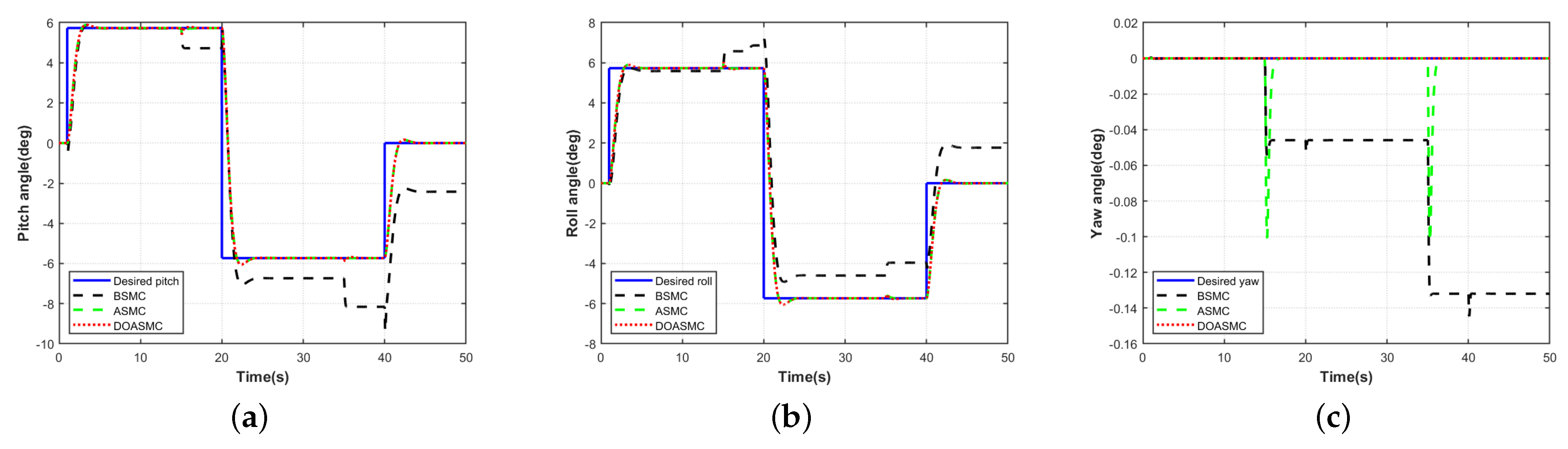
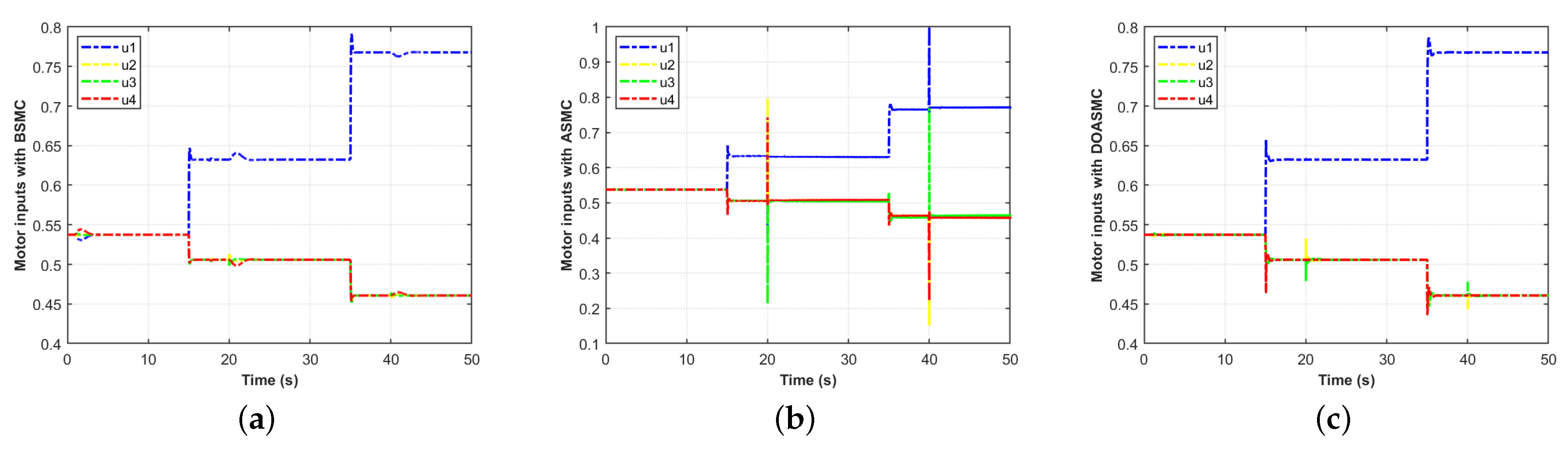
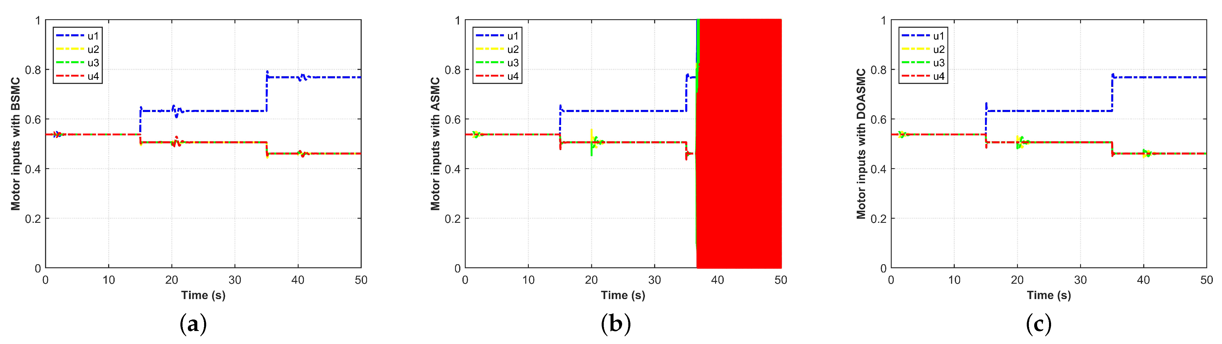
4. Simulation Results and Discussions

Simulation tests of three different control approaches are created to verify the effectiveness of the proposed methods in this section. The standard integral SMC strategy is used in the first control method (BSMC) for both the attitude and position loops. The second control method (ASMC) uses the ASMC strategy proposed in Section 3 to create the attitude and position loops. In the third control method (DOASMC), the attitude loop is designed using the ASMC strategy with the disturbance observer, and the position loop is designed using the ASMC strategy. The design parameters for the demonstrated three control methods are illustrated in Table 2.
The three simulation scenarios in this section are provided in Table 3 and explained in detail as follows. The attitude loop is tested in Scenario 1, which consists of the actuator #1 fault. The level of the control effectiveness is changed to 80 % at 15 s and changed to 60 % at 35 s. Scenario 2 is designed to introduce disturbances into the system in addition to the considered actuator fault in Scenario 1. Scenario 3 is tested for the attitude and position loops, where there are the actuator #1 fault, disturbances and parametric uncertainties. The level of the control effectiveness is changed to 80 % at 15 s and changed to 70 % at 35 s. Abrupt changes in the control effectiveness level of the system attributed to the actuator fault are shown in Figure 4a,b. The moment of inertia-related uncertainties is set as 30% of the nominal value. The injected disturbance is displayed in Figure 4c and modeled as
d ϕ = 10 sin ( 2 π t ) ( t 0 ) d θ = 10 sin ( 2 π t ) ( t 0 )
The desired trajectory is a horizontal rectangle, which is expressed as
X d = t 10 10 [ sign ( t 10 ) sign ( t 20 ) ] + [ sign ( t 20 ) sign ( t 30 ) ] + 40 t 10 [ sign ( t 30 ) sign ( t 40 ) ] Y d = t 20 10 [ sign ( t 20 ) sign ( t 30 ) ] + [ sign ( t 30 ) sign ( t 40 ) ] + 50 t 10 [ sign ( t 40 ) sign ( t 50 ) ] Z d = 2
To quantitatively evaluate the control ability, the root mean square error (RMSE) of the attitude tracking is defined as follows:
R M S E = t 0 t 1 Θ ˜ 2 d t t 1 t 0
where [ t 0 , t 1 ] covers the entire simulation.

4.1. Scenario 1

Scenario 1 only includes the actuator #1 fault, whose control effectiveness is changed to 80% at 15 s and to 60% at 35 s. In the event of the actuator #1 fault, the attitude tracking performances and PWM inputs under three control approaches are illustrated in Figure 5 and Figure 6. Before the actuator fault occurs at 15 s, the control approaches enable the system to operate safely and to converge to zero tracking error. When the fault occurs after 15 s, DOASMC can maintain superior tracking performance. The excellent control performance in the pitch and roll directions of ASMC are also demonstrated in Figure 5, while the yaw direction shows fluctuating at the beginning of the fault but no tracking error in the end, reflecting the robustness and fault tolerance of the presented method. The tracking performance of BSMC deteriorates with the increasing level of the actuator fault.

4.2. Scenario 2

Based on Scenario 1, Scenario 2 presumes that disturbances are added, which are introduced into the system to further emphasize the benefits of the presented fault-tolerant control method. The attitude tracking and PWM inputs are manifested in Figure 7 and Figure 8. The attitude tracking of the ASMC approach shows chattering in Figure 7. Only DOASMC maintains the superior performance in this situation, demonstrating that the proposed method can operate steadily in the event of significant actuator fault and disturbances.
To ensure tracking performance, ASMC requires more control effort compared to BSMC and DOASMC, and the motor inputs oscillate, which may render the system unstable, according to Figure 8b. The PWM inputs of BSMC and DOASMC are similar, but the performance of DOASMC is better, which indicates that DOASMC achieves better tracking performance without sacrificing additional control effort.

4.3. Scenario 3

In Scenario 3, the system is presumptively subject to the uncertainties, disturbances and actuator faults. The effectiveness of actuator #1 decreases due to the fault, dropping to 80% at 15 s and to 70% at 35 s. The third scenario tests the attitude and trajectory tracking performance of different approaches. The trajectory tracking performance is displayed in Figure 9. The task of trajectory tracking can be accurately accomplished by using the approaches of ASMC and DOASMC. The unfavorable performance of the BSMC in trajectory tracking is an expected outcome given that the attitude loop is an internal process of the position loop and that there are significant attitude errors in Figure 5 and Figure 7. According to Figure 10, it can be concluded that DOASMC has a faster convergence speed against ASMC. The PWM inputs are displayed in Figure 11.
The attitude tracking performance indices are presented in Table 4. The attitude tracking performance indices of ASMC and DOASMC are superior to BSMC in the simulation scenarios, demonstrating the effectiveness of the proposed method. Additionally, the best performance comes from DOASMC, illustrating the ability of the observer in enhancing the performance of the control system.

5. Conclusions

An adaptive sliding mode control (ASMC) strategy enhanced with a disturbance observer is proposed for position and attitude tracking of a quadrotor UAV in the event of actuator faults and external disturbances in this paper. Different mechanisms are used to reduce the adverse effects of actuator faults and disturbances. The proposed approach is used to address the negative effects of actuator faults. It can adaptively adjust the gain of the continuous and discontinuous control parts to prevent system chattering caused by the excessive gain of the discontinuous parts. A disturbance observer is further introduced to suppress the impact of disturbances and reduce the gain of the discontinuous control part. A series of comparative simulation tests confirm the superiority of the approach. However, there is no consideration given to the faults introduced into multiple actuators in this paper, which we will be dealing with in our future research. In addition, real flight testing of the presented approach will be conducted in our future research works.

Author Contributions

Conceptualization, X.H. and B.W.; methodology, X.H., B.W., Y.S. and Y.F.; validation, Y.S. and Y.F.; formal analysis, X.H., B.W., Y.S., Y.F. and N.L.; writing—original draft, X.H.; writing—review and editing, B.W., Y.S. and N.L.; visualization, X.H. and Y.F.; supervision, B.W. and N.L. All authors have read and agreed to the published version of the manuscript.

Funding

This work was supported in part by National Natural Science Foundation of China under Grant 62003266 and Grant 62003272, in part by the Industry-University-Research Innovation Foundation for the Chinese Ministry of Education under Grant 2021ZYA07002.

Data Availability Statement

The data that support the findings of this study are available from the corresponding author upon reasonable request.

Conflicts of Interest

The authors declare no conflict of interest.

References

  1. Griffin, B.; Fierro, R.; Palunko, I. An autonomous communications relay in GPS-denied environments via antenna diversity. J. Def. Model. Simul. 2012, 9, 33–44. [Google Scholar] [CrossRef]
  2. Ji, S.; Tang, H.; Ming, Y.; Zhao, C. Design of high automatic target recognition unmanned reconnaissance system based on YOLOv5. In Proceedings of the 2022 IEEE 4th International Conference on Civil Aviation Safety and Information Technology (ICCASIT), Dali, China, 12–14 October 2022; pp. 1446–1449. [Google Scholar]
  3. Cruz, P.J.; Fierro, R. Cable-suspended load lifting by a quadrotor UAV: Hybrid model, trajectory generation, and Control. Auton. Robot. 2017, 41, 1629–1643. [Google Scholar] [CrossRef]
  4. Ghamry, K.A.; Zhang, Y.M. Cooperative control of multiple UAVs for forest fire monitoring and detection. In Proceedings of the 2016 12th IEEE/ASME International Conference on Mechatronic and Embedded Systems and Applications (MESA), Auckland, New Zealand, 29–31 August 2016; pp. 1–6. [Google Scholar]
  5. Duggal, V.; Sukhwani, M.; Bipin, K.; Reddy, G.S.; Krishna, K.M. Plantation monitoring and yield estimation using autonomous quadcopter for precision agriculture. In Proceedings of the 2016 IEEE International Conference on Robotics and Automation, Stockholm, Sweden, 16–21 May 2016; pp. 5121–5127. [Google Scholar]
  6. Araar, O.; Aouf, N. Visual servoing of a quadrotor uav for autonomous power lines inspection. In Proceedings of the 22nd Mediterranean Conference on Control and Automation, Palermo, Italy, 16–19 June 2014; pp. 1418–1424. [Google Scholar]
  7. Budiharto, W.; Irwansyah, E.; Suroso, J.S.; Chowanda, A.; Ngarianto, H.; Gunawan, A.A.S. Mapping and 3D modelling using quadrotor drone and GIS software. J. Big Data 2021, 8, 48. [Google Scholar] [CrossRef]
  8. Martins, L.; Cardeira, C.; Oliveira, P. Inner-outer feedback linearization for quadrotor control: Two-step design and validation. Nonlinear Dyn. 2022, 110, 479–495. [Google Scholar] [CrossRef]
  9. Pan, J.; Shao, B.; Xiong, J.; Zhang, Q. Attitude control of quadrotor UAVs based on adaptive sliding mode. Int. J. Control Autom. Syst. 2023, 21, 2698–2707. [Google Scholar] [CrossRef]
  10. Liu, K.; Wang, R. Antisaturation command filtered backstepping control-based disturbance rejection for a quadrotor UAV. IEEE Trans. Circuits Syst. II Express Briefs 2021, 68, 3577–3581. [Google Scholar]
  11. Amin, R.; Aijun, L.; Shamshirband, S. A review of quadrotor UAV: Control methodologies and performance evaluation. Int. J. Autom. Control 2016, 10, 87–103. [Google Scholar] [CrossRef]
  12. Maaruf, M.; Mahmoud, M.S.; Ma’arif, A. A survey of control methods for quadrotor UAV. Int. J. Robot. Control Syst. 2022, 2, 652–665. [Google Scholar] [CrossRef]
  13. Mo, H.; Farid, G. Nonlinear and adaptive intelligent control techniques for quadrotor UAV—A survey. Asian J. Control 2019, 21, 989–1008. [Google Scholar] [CrossRef]
  14. Rahmat, M.F.; Eltayeb, A.; Basri, M.A.M. Adaptive feedback linearization controller for stabilization of quadrotor UAV. Int. J. Integr. Eng. 2020, 12, 1–17. [Google Scholar]
  15. Wu, X.; Xiao, B.; Qu, Y. Modeling and sliding mode-based attitude tracking control of a quadrotor UAV with time-varying mass. ISA Trans. 2022, 124, 436–443. [Google Scholar] [CrossRef]
  16. Liu, W.; Cheng, X.; Zhang, J. Command filter-based adaptive fuzzy integral backstepping control for quadrotor UAV with input saturation. J. Frankl. Inst. 2023, 360, 484–507. [Google Scholar] [CrossRef]
  17. Fourlas, G.K.; Karras, G.C. A survey on fault diagnosis and fault-tolerant control methods for unmanned aerial vehicles. Machines 2021, 9, 197. [Google Scholar] [CrossRef]
  18. Chamseddine, A.; Theilliol, D.; Zhang, Y.M.; Rabbath, C.A. Active fault-tolerant control system design with trajectory replanning against actuator faults and saturation: Application to a quadrotor unmanned aerial vehicle. Int. J. Adapt. Control Signal Process. 2015, 29, 1–23. [Google Scholar] [CrossRef]
  19. Merheb, A.R.; Noura, H.; Bateman, F. Passive fault tolerant control of quadrotor uav using regular and cascaded sliding mode Control. In Proceedings of the 2013 Conference on Control and Fault-Tolerant Systems, Nice, France, 9–11 October 2013; pp. 330–335. [Google Scholar]
  20. Wang, T.; Xie, W.; Zhang, Y.M. Sliding mode fault tolerant control dealing with modeling uncertainties and actuator faults. ISA Trans. 2012, 51, 386–392. [Google Scholar] [CrossRef] [PubMed]
  21. Zeghlache, S.; Mekki, H.; Bouguerra, A.; Djerioui, A. Actuator fault tolerant control using adaptive RBFNN fuzzy sliding mode controller for coaxial octorotor UAV. ISA Trans. 2018, 80, 267–278. [Google Scholar] [CrossRef]
  22. Eliker, K.; Zhang, W. Finite-time adaptive integral backstepping fast terminal sliding mode control application on quadrotor UAV. Int. J. Control Autom. Syst. 2020, 18, 415–430. [Google Scholar]
  23. Ha, L.N.N.T.; Hong, S.K. Robust dynamic sliding mode control-based PID–super twisting algorithm and disturbance observer for second-order nonlinear systems: Application to UAVs. Electronics 2019, 8, 760. [Google Scholar] [CrossRef]
  24. Zhang, C.; Zhang, G.; Dong, Q. Multi-variable finite-time observer-based adaptive-gain sliding mode control for fixed-wing UAV. IET Control Theory Appl. 2021, 15, 223–247. [Google Scholar] [CrossRef]
  25. Zheng, E.H.; Xiong, J.J.; Luo, J.L. Second order sliding mode control for a quadrotor UAV. ISA Trans. 2014, 53, 1350–1356. [Google Scholar] [CrossRef]
  26. Nguyen, L.V.; Phung, M.D.; Ha, Q.P. Iterative Learning Sliding Mode Control for UAV Trajectory Tracking. Electronics 2021, 10, 2474. [Google Scholar] [CrossRef]
  27. Zheng, B.; Wu, Y.; Li, H.; Chen, Z. Adaptive sliding mode attitude control of quadrotor uavs based on the delta operator framework. Symmetry 2022, 14, 498. [Google Scholar] [CrossRef]
  28. Hassani, H.; Mansouri, A.; Ahaitouf, A. A new robust adaptive sliding mode controller for quadrotor UAV flight. In Proceedings of the 2020 IEEE 2nd International Conference on Electronics, Control, Optimization and Computer Science (ICECOCS), Kenitra, Morocco, 2–3 December 2020; pp. 1–6. [Google Scholar]
  29. Islam, S.; Faraz, M.; Ashour, R.; Cai, G.; Dias, J.; Seneviratne, L. Adaptive sliding mode control design for quadrotor unmanned aerial vehicle. In Proceedings of the 2015 International Conference on Unmanned Aircraft Systems (ICUAS), Denver, CO, USA, 9–12 June 2015; pp. 34–39. [Google Scholar]
  30. Mofid, O.; Mobayen, S. Adaptive sliding mode control for finite-time stability of quad-rotor UAVs with parametric uncertainties. ISA Trans. 2018, 72, 1–14. [Google Scholar] [CrossRef]
  31. Bouadi, H.; Cunha, S.S.; Drouin, A.; Mora-Camino, F. Adaptive sliding mode control for quadrotor attitude stabilization and altitude tracking. In Proceedings of the 2011 IEEE 12th International Symposium on Computational Intelligence and Informatics (CINTI), Budapest, Hungary, 21–22 November 2011; pp. 449–455. [Google Scholar]
  32. Wang, B.; Shen, Y.Y.; Li, N.; Zhang, Y.M.; Gao, Z.H. An adaptive sliding mode fault-tolerant control of a quadrotor unmanned aerial vehicle with actuator faults and model uncertainties. Int. J. Robust Nonlinear Control 2023, 1–17. [Google Scholar] [CrossRef]
  33. Wang, B.; Zhu, D.; Han, L.; Gao, H.; Gao, Z.; Zhang, Y.M. Adaptive fault-tolerant control of a hybrid canard rotor/wing UAV under transition flight subject to actuator faults and model uncertainties. IEEE Trans. Aerosp. Electron. Syst. 2023, 59, 4559–4574. [Google Scholar] [CrossRef]
  34. Chaoraingern, J.; Tipsuwanporn, V.; Numsomran, A. Modified adaptive sliding mode control for trajectory tracking of mini-drone quadcopter unmanned aerial vehicle. Int. J. Intell. Eng. Syst. 2020, 13, 145–158. [Google Scholar] [CrossRef]
  35. Oh, H.; Kim, S.; Tsourdos, A.; White, B.A. Decentralised standoff tracking of moving targets using adaptive sliding mode control for UAVs. J. Intell. Robot. Syst. 2014, 76, 169–183. [Google Scholar] [CrossRef]
  36. Eltayeb, A.; Rahmat, M.F.; Basri, M.A.M.; Eltoum, M.M.; El-Ferik, S. An improved design of an adaptive sliding mode controller for chattering attenuation and trajectory tracking of the quadcopter UAV. IEEE Access 2020, 8, 205968–205979. [Google Scholar] [CrossRef]
  37. Huang, T.; Huang, D.; Wang, Z.; Dai, X.; Shah, A. Generic adaptive sliding mode control for a quadrotor UAV system subject to severe parametric uncertainties and fully unknown external disturbance. Int. J. Control Autom. Syst. 2021, 19, 698–711. [Google Scholar] [CrossRef]
  38. Huang, T.; Huang, D.; Wang, Z.; Shah, A. Robust tracking control of a quadrotor UAV based on adaptive sliding mode controller. Complexity 2019, 2019, 7931632. [Google Scholar] [CrossRef]
  39. Hassani, H.; Mansouri, A.; Ahaitouf, A. Robust autonomous flight for quadrotor UAV based on adaptive nonsingular fast terminal sliding mode Control. Int. J. Dyn. Control 2021, 9, 619–635. [Google Scholar] [CrossRef]
  40. Lin, X.; Yu, Y.; Sun, C.Y. A decoupling control for quadrotor UAV using dynamic surface control and sliding mode disturbance observer. Nonlinear Dyn. 2019, 97, 781–795. [Google Scholar] [CrossRef]
  41. Ahmed, N.; Chen, M.; Shao, S. Disturbance observer based tracking control of quadrotor with high-order disturbances. IEEE Access 2020, 8, 8300–8313. [Google Scholar] [CrossRef]
  42. Kang, B.; Miao, Y.; Liu, F.; Duan, J.; Wang, K.; Jiang, S. A second-order sliding mode controller of quad-rotor UAV based on PID sliding mode surface with unbalanced load. J. Syst. Sci. Complex. 2021, 34, 520–536. [Google Scholar] [CrossRef]
  43. Li, B.; Gong, W.; Yang, Y.; Xiao, B.; Ran, D. Appointed fixed time observer-based sliding mode control for a quadrotor UAV under external disturbances. IEEE Trans. Aerosp. Electron. Syst. 2021, 58, 290–303. [Google Scholar] [CrossRef]
  44. Ahmed, N.; Chen, M. Sliding mode control for quadrotor with disturbance observer. Adv. Mech. Eng. 2018, 10, 1–16. [Google Scholar] [CrossRef]
  45. Fethalla, N.; Saad, M.; Michalska, H.; Ghommam, J. Robust observer-based dynamic sliding mode controller for a quadrotor UAV. IEEE Access 2018, 6, 45846–45859. [Google Scholar] [CrossRef]
  46. Wang, B.; Zhang, Y.M.; Zhang, W. A Composite Adaptive Fault-Tolerant Attitude Control for a Quadrotor UAV with Multiple Uncertainties. J. Syst. Sci. Complex. 2022, 35, 81–104. [Google Scholar] [CrossRef]
  47. Chen, M.; Shi, P.; Lim, C.C. Robust constrained control for MIMO nonlinear systems based on disturbance observer. IEEE Trans. Autom. Control 2015, 60, 3281–3286. [Google Scholar] [CrossRef]
  48. Zhang, Z.; Wang, F.; Guo, Y.; Hua, C. Multivariable sliding mode backstepping controller design for quadrotor UAV based on disturbance observer. Sci. China Inf. Sci. 2018, 61, 112207. [Google Scholar] [CrossRef]
  49. Besnard, L.; Shtessel, Y.B.; Landrum, B. Quadrotor vehicle control via sliding mode controller driven by sliding mode disturbance observer. J. Frankl. Inst. 2012, 349, 658–684. [Google Scholar] [CrossRef]
  50. Nguyen, N.P.; Mung, N.X.; Thanh, H.L.N.N.; Huynh, T.T.; Lam, N.T.; Hong, S.K. Adaptive sliding mode control for attitude and altitude system of a quadcopter UAV via neural network. IEEE Access 2021, 9, 40076–40085. [Google Scholar] [CrossRef]
  51. Nguyen, N.P.; Hong, S.K. Fault-tolerant control of quadcopter UAVs using robust adaptive sliding mode approach. Energies 2018, 12, 95. [Google Scholar] [CrossRef]
  52. Hadi, R.; Sima, A. Neural network-based adaptive sliding mode control design for position and attitude control of a quadrotor UAV. Aerosp. Sci. Technol. 2019, 91, 12–27. [Google Scholar]
  53. Wang, B.; Yu, X.; Mu, L.X.; Zhang, Y.M. Disturbance observer-based adaptive fault-tolerant control for a quadrotor helicopter subject to parametric uncertainties and external disturbances. Mech. Syst. Signal Process. 2019, 120, 727–743. [Google Scholar] [CrossRef]
Figure 1. The studied quadrotor UAV.
Drones 07 00541 g001
Figure 2. The definition of the reference frames of the quadrotor UAV.
Drones 07 00541 g002
Figure 3. Schematic of the proposed method.
Drones 07 00541 g003
Figure 4. The considered actuator fault and disturbance in simulation scenarios.
Drones 07 00541 g004
Figure 5. Attitude tracking performance in Scenario 1. (a) Reponse of pitch angle, (b) Reponse of roll angle, (c) Reponse of yaw angle.
Drones 07 00541 g005
Figure 6. Control inputs performance in Scenario 1. (a) BSMC; (b) ASMC; (c) DOASMC.
Drones 07 00541 g006
Figure 7. Attitude tracking performance in Scenario 2. (a) Reponse of pitch angle; (b) Reponse of roll angle; (c) Reponse of yaw angle.
Drones 07 00541 g007
Figure 8. Control inputs performance in Scenario 2. (a) BSMC, (b) ASMC, (c) DOASMC.
Drones 07 00541 g008
Figure 9. Trajectory tracking performance in Scenario 3 (a) x and y, (b) z.
Drones 07 00541 g009
Figure 10. Attitude tracking error in Scenario 3. (a) Pitch angle, (b) Roll angle, (c) Yaw angle.
Drones 07 00541 g010
Figure 11. Control inputs performance in Scenario 3. (a) BSMC, (b) ASMC, (c) DOASMC.
Drones 07 00541 g011
Table 1. The parameters of the studied quadrotor UAV.
ParameterExplanationValue
mtotal mass1.121 kg
L p i t c h distance between motor #1 and motor #20.2136 m
L r o l l distance between motor #3 and motor #40.1758 m
I x x rolling moment of inertia0.01 kgm 2
I y y pitching moment of inertia0.0082 kgm 2
I z z yawing moment of inertia0.0148 kgm 2
Table 2. Design parameters for the three control methods.
Control LoopController k 1 k 2 k 3
attitude ϕ 404001
θ 404001
ψ 404001
positionX0.20.010.1
Y0.20.010.1
Z2110
Table 3. The simulation scenarios.
Scenario 1Scenario 2Scenario 3
20% loss of effectiveness fault in actuators #1 at 15 s
40% loss of effectiveness fault to actuators #1 at 35 s
30% loss of effectiveness fault to actuators #1 at 35 s
Disturbances cover the entire simulation.
Parametric uncertainties cover the entire simulation.
Table 4. Attitude tracking performance indices.
Simulation ScenarioAttitude-AngleBSMC (deg)ASMC (deg)DOASMC (deg)
1 ϕ 1.22290.02090.0190
θ 1.21770.02140.0197
ψ 0.05730.00820.0000
2 ϕ 1.56680.04180.0238
θ 1.56140.04180.0238
ψ 0.07770.02350.0035
3 ϕ 1.03240.01890.0178
θ 1.02840.01860.0179
ψ 0.04430.00420.0032
Disclaimer/Publisher’s Note: The statements, opinions and data contained in all publications are solely those of the individual author(s) and contributor(s) and not of MDPI and/or the editor(s). MDPI and/or the editor(s) disclaim responsibility for any injury to people or property resulting from any ideas, methods, instructions or products referred to in the content.

