Article

The Design of Improved Series Hybrid Power System Based on Compound-Wing VTOL

Institute of Electronic and Electrical Engineering, Civil Aviation Flight University of China, Chengdu 641418, China
*
Author to whom correspondence should be addressed.
Drones 2024, 8(11), 634; https://doi.org/10.3390/drones8110634
Submission received: 24 September 2024 / Revised: 24 October 2024 / Accepted: 28 October 2024 / Published: 1 November 2024

Abstract

:
Hybrid power systems are now widely utilized in a variety of vehicle platforms due to their efficacy in reducing pollution and enhancing energy utilization efficiency. Nevertheless, the existing vehicle hybrid systems are of a considerable size and weight, rendering them unsuitable for integration into 25 kg compound-wing UAVs. This study presents a design solution for a compound-wing vertical takeoff and landing unmanned aerial vehicle (VTOL) equipped with an improved series hybrid power system. The system comprises a 48 V lithium polymer battery(Li-Po battery), a 60cc internal combustion engine (ICE), a converter, and a dedicated permanent magnet synchronous machine (PMSM) with four motors, which collectively facilitate dual-directional energy flow. The four motors serve as a load and lift assembly, providing the requisite lift during the take-off, landing, and hovering phases, and in the event of the ICE thrust insufficiency, as well as forward thrust during the level cruise phase by mounting the variable pitch propeller directly on the ICE. The entire hybrid power system of the UAV undergoes numerical modeling and experimental simulation to validate the feasibility of the complete hybrid power configuration. The validation is achieved by comparing and analyzing the results of the numerical simulations with ground tests. Moreover, the effectiveness of this hybrid power system is validated through the successful completion of flight test experiments. The hybrid power system has been demonstrated to significantly enhance the endurance of vertical flight for a compound-wing VTOL by more than 25 min, thereby establishing a solid foundation for future compound-wing VTOLs to enable multi-destination flights and multiple takeoffs and landings.

1. Introduction

In recent years, unmanned aerial vehicles (UAVs) have found extensive applications in agriculture, real-time traffic monitoring and control, high-speed delivery, topographic surveying, and various other fields [1]. Due to their significant advantages and potential across multiple domains, enhancing the aforementioned performance has become a prominent focus within both academic research and industry [2,3,4,5].
An ideal UAV should demonstrate exceptional performance in terms of long-range endurance, operational flexibility, cost-effective maintenance, and low pollution emissions. The configuration of the UAV is one of the key factors that significantly impact its overall performance [6]. Based on aerodynamic shape, typical UAVs can be classified into fixed-wing and multi-rotor configurations as depicted in Figure 1. Among these options, the fixed-wing configuration is widely equipped for high-speed flights and heavy payload requirements [7]. In comparison to other configurations, the multi-rotor design offers advantages such as convenient deployment and flexible maneuverability [8].
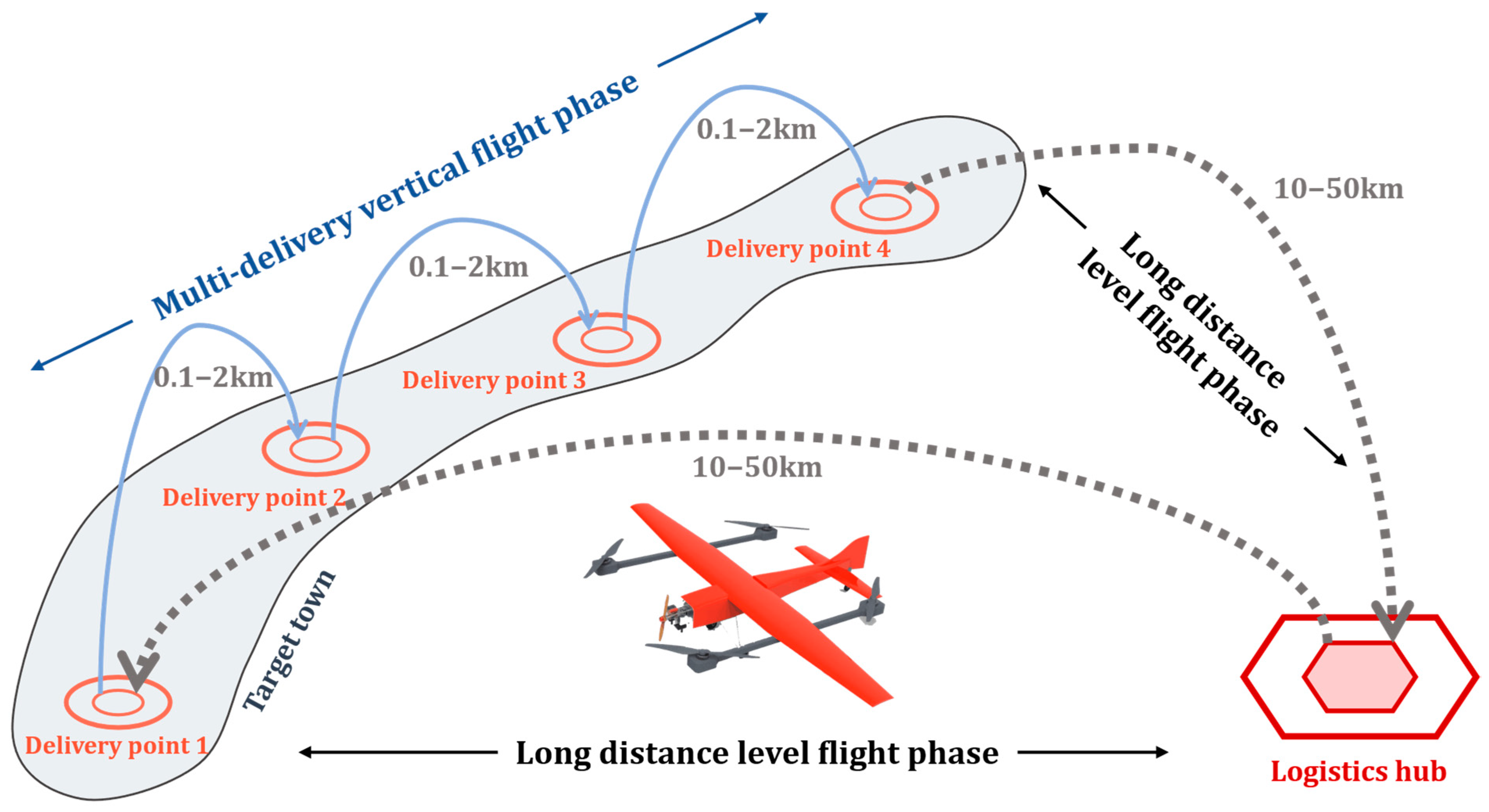
The flight profile is another factor that can impact the performance of UAVs. The settings of the flight profile primarily depend on the application environment and mission objectives of the UAV [9]. One typical flight profile for UAVs is multi-point goods delivery or device inspection, as depicted in Figure 2. To successfully accomplish missions like these, it is essential for UAVs to possess high-speed capabilities during level flight modes and exceptional maneuverability during vertical flight modes.
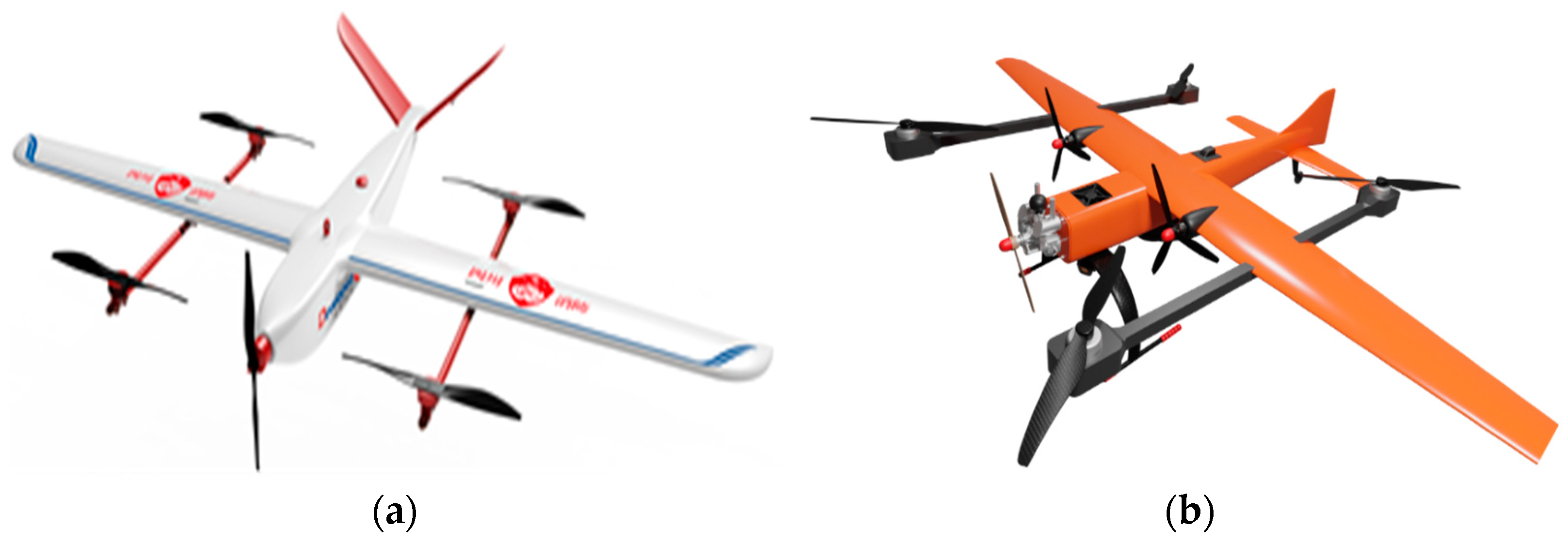
In order to address the aforementioned issues, the utilization of drooping multi-rotor unmanned aerial vehicles (UAVs) [10] and tilting multi-rotor UAVs represents a potential solution [11,12]. However, the pitched multi-rotor UAV has a limited payload capacity and operates at a relatively slow speed. It is less efficient than other UAVs. Tilt-rotor UAVs are more complex to control and require a more sophisticated tilting structure. In contrast, compound-wing UAVs combine the advantages of both [13]. A compound-wing UAV has been proposed that combines vertical maneuverability with high-speed horizontal flight capability. The compound-wing UAV is equipped with both rotary systems and level propulsion, enabling it to achieve both vertical mobility and level flight concurrently, as depicted in Figure 3.
The power system, as the core component of VTOLs, plays a crucial role in extending their endurance and expanding their applications [14,15]. Two main types of propulsion subsystems widely used in VTOLs are the electrical propulsion system (consisting of motor and battery) and the ICE [16]. To meet the requirements for long endurance, low pollution emissions, and high fuel efficiency simultaneously, a hybrid power system has been proposed [17,18]. The researchers evaluated the performance of four electric propulsion systems (parallel hybrid, turbo-electric, series hybrid, and pure electric propulsion systems) on a compound-wing UAV by comparing them and demonstrated that the hybrid system has notable advantages in reducing the weight of the UAV, increasing the cruising altitude and range, and enhancing the payload capability. Furthermore, a comparison between the fuel cell hybrid system and the oil–electric hybrid system, among others, substantiates the assertion that the oil–electric hybrid system represents the most viable option within the existing context [19]. However, the design and integration of hybrid systems is more complex than that of pure electric systems, and the development and manufacturing costs are higher [20,21]. By contrast, hybrid fuel cell systems must be enhanced in order to ensure enhanced safety and greater efficiency. As a result, the hybrid system represents the optimal choice in the circumstances prevailing at the time of writing, with researchers also developing a parallel hybrid system for use with compound-wing UAVs [22]. However, the parallel hybrid system is too complex, heavy and voluminous to be applicable to the compound-wing UAV with a maximum takeoff weight (MTOW) of 25 kg elected in this paper.
To address the aforementioned issue, this paper proposes a 25 kg MTOW hybrid powered compound-wing VTOL, as depicted in Figure 3b. The compound-wing VTOL incorporates a quadrotor to fulfill vertical mobility requirements. Specifically designed for the VTOL, the architecture of the gasoline–electrical hybrid power system adopts an improved series configuration. The compound-wing VTOL transitions into horizontal flight mode and is propelled by a variable pitch propeller (VPP) that is driven directly by ICE. Therefore, this paper presents a numerical model of the hybrid powertrain system and compares the numerical results generated under the model conditions with those obtained from direct measurement in the physical experiments referenced in this paper. The findings indicate that the numerical analysis outcomes align with the experimental results, thereby validating the rationality of the hybrid power system design proposed in this paper through a comprehensive assessment encompassing both physical experimentation and numerical simulations. By comparison with UAVs with other power systems, this type of power system has the following characteristics: (1) innovative hybrid system has been constructed for the compound-wing VTOL, with the goal of increasing the endurance of vertical flight and improving the vehicle’s ability to fly complex missions; (2) innovative design of the pitch propeller ensures that propulsion and power generation can be decoupled, and the performance of the pitch propeller has been verified by ground tests; and (3) the system has been verified by ground tests and test flights, and its feasibility is sufficiently ensured.
The following content is divided into four sections. Section 2 aims to provide an architecture of the power system. Section 3 presents models of components and design details. Section 4 presents a simulation of thrust and conducts a ground test to simulate the flight profile. Based on ground test results, a prototype experiment is conducted. Finally, findings are concluded in Section 5.

2. The Architecture and Description of the Hybrid Power System

2.1. The Architecture of Hybrid Power System

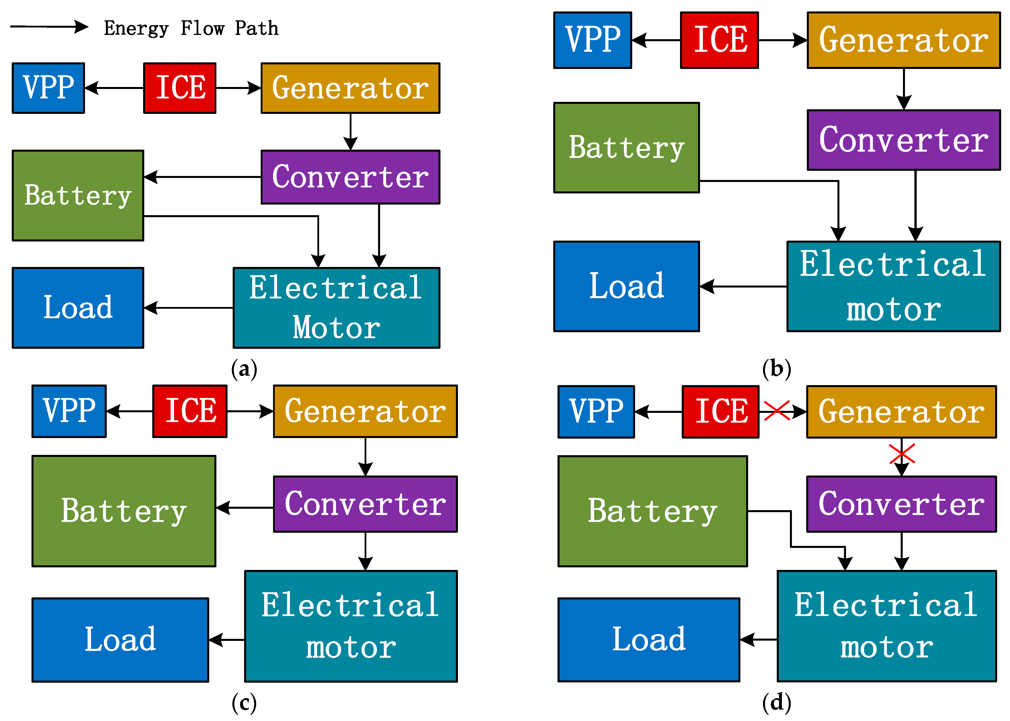
To enhance the performance of the hybrid power system and prolong the endurance of the hybrid compound-wing VTOL, this study proposes an improved series hybrid power architecture, as illustrated in Figure 4a. In this configuration, a VPP that is driven directly by ICE serves as the primary propulsion subsystem for the VTOL. The ICE drives the permanent magnet synchronous motor (PMSM) to generate electricity. Following rectification and conversion to DC, the electricity is directly output to the motor, while any excess power is output to the battery (cruise phase). Therefore, this series hybrid power system can achieve a dual-directional flow of energy and improve the energy utilization efficiency of the whole process, due to the ICE always working in the optimal operating range. Extending the duration of hovering flight of the whole vehicle is theoretically achieved.
The improved series hybrid architecture, as mentioned above, is an appropriate hybrid power system for light hybrid compound-wing VTOL aircraft. In this architecture, the variable pitch propeller is directly connected to the output shaft of ICE on one side, while the permanent magnet synchronous motor (PMSM) is connected to the output shaft on the other side. Within this improved series hybrid architecture, there are three operational modes: full thrust mode, cruise thrust mode, and emergency thrust mode.
The energy flow path in the full thrust mode can be seen in Figure 4b. The figure illustrates that in the case of vertical lift, the synchronous motor is driven by the internal combustion engine to generate electricity, with the generated current passing through the three-phase rectifier and being transformed into direct current, which is then partly outputted. The remaining output is directed to the motor via the control board, ensuring that the compound-wing UAV is capable of vertical lift under load. This output is provided to the battery through the control board for charging the Li-Po batteries.
In cruise thrust mode, the battery can absorb excess power and charge accordingly, allowing the ICE to operate at optimal efficiency. The internal combustion engine rotates the variable pitch paddles to generate the forward thrust required for the aircraft to maintain its position in flight. The fixed wing mounted on the aircraft in the forward process generates lift, which reduces the actual power required by the four motors. The excess current generated by the synchronous motors can be converted to DC through a rectifier to charge the battery. The energy flow path during cruise thrust mode is illustrated in Figure 4c.
Energy flow path in the emergency thrust mode, which illustrates the emergency mode, which is triggered in the event of an internal combustion engine failure that impairs its ability to generate pulling force. In such a scenario, the synchronous motors are designed to generate electricity. However, when this fails, the batteries will supply power directly to the four drogue motors, ensuring the safe landing of the UAV. The energy flow path is illustrated in Figure 4d.

2.2. Main Components of Hybrid Power System

As this system component is used in a 25 kg class UAV and must meet the maximum cruising speed of over 30 m per second, the motor and ICE are considered to generate lift and thrust under these conditions. Under these conditions, weight is the primary consideration for the rest of the system components, because the more weight used, the more energy is consumed during vertical take-off. The figure (Figure 5) below shows some of the conditions that need to be considered when selecting or designing the five main components of the system.
Energy and weight being two conflicting battery choices, this paper chooses a 1.5 kg Li-Po battery, which can provide 5.76 kW of energy at the same time. While the ICE meets the thrust feasible condition of maximum RPM, the location of the ICE should also be considered, either at the nose or tail of the aircraft. In view of its vibration, heat dissipation and ease of disassembly, the nose of the aircraft is the location of choice for this work. For PMSM, the main consideration is its power generation, this paper chooses 2 kW PMSM. The rest of the components are shown in the above figure after the combination of factors to make the appropriate choice.
The VPP serves as the primary component for generating forward thrust during the level flight mode. By adjusting the pitch angle, the airflow direction can be altered, optimizing fuel consumption and propulsion efficiency. Additionally, in the hovering mode, the VPP facilitates cooling of the entire propulsion system. The variation in VPP is controlled by a servo motor installed beneath the ICE’s forward output shaft.
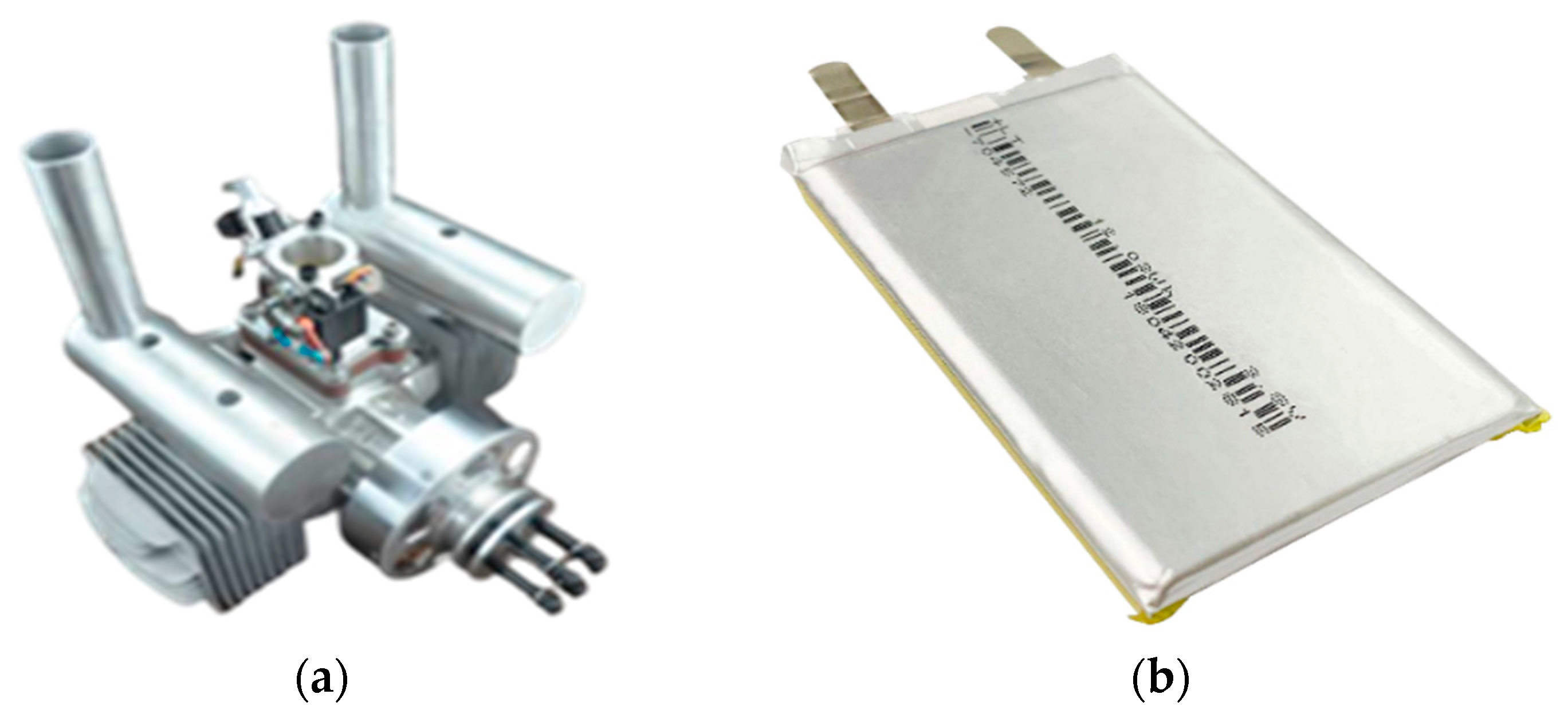
In the improved series hybrid architecture, ICE serves as the primary power source for powering lift rotor, VPP, and avionics devices. In addition to the ICE, a lithium polymer (Li-Po) battery is used as another power source in this VTOL configuration, considering its energy density and performance in terms of change and discharge. The propulsion system operates at a working voltage of 48 V, with each single cell typically ranging from 3.8 V to 4.2 V. To achieve this voltage requirement, a connection format of 12 series and 1 parallel is adopted. Furthermore, besides functioning as a chemical power supply, the battery also plays a role in stabilizing the system’s voltage fluctuation throughout the entire flight profile. The typical ICE and battery are illustrated in Figure 6a,b.
The stator is composed of a three-phase winding, which enables the generation of a rotating magnetic field. Consequently, the rotor can be driven and operated stably under stable electric power (48 V) drive. In the improved series hybrid power architecture, parameters such as the rotor’s magnetic strength and air gap width are crucial for maintaining stable operation and achieving high efficiency throughout the entire system. Serving as another energy converter, a three-phase rectifier plays a pivotal role in directing energy flow from the PMSM to both the battery and loads by rectifying AC current into DC current that can be utilized by these components.
The rotors and electrical motors constitute the primary vertical take-off and landing facilities of the improved series hybrid architecture, collectively referred to as the rotary system. In hovering mode, the LRS generates the necessary lift force for VTOL operation. Unlike the VPP, which relies on horizontal movement, the lift motor rotor requires additional energy to counteract gravity and provide sufficient lift force. The brushless direct current motor(DC motor), PMSM, and converter are depicted in Figure 7a–c.
The VPP, ICE, PMSM, Rectifier, Li-Po battery, and lift motor rotors contribute to the improved series hybrid architecture in the compound-wing VTOL. As mentioned above, the improved series hybrid architecture is not the only power system that can be applied to the compound-wing VTOL. However, in comparison to the fuel hybrid system and the parallel hybrid system previously discussed, the series hybrid system is capable of achieving efficient energy utilization, as well as miniaturization and lightweighting. This makes it an optimal choice for use in lightweight (25 kg MTOW) UAVs.

3. The Design and Implement of the System

3.1. The Practical Requirements of Internal Combustion Engine

Considering that the compound-wing VTOL typically operates and flies at altitudes below 1000 m and airspeeds below 120 km/h, it is equipped with a gasoline piston engine. The primary material used for this engine is aluminum alloy, and monolithic casting technique is employed to reduce its volume and weight. To further simplify the structure and minimize weight, both the water-cooled system and independent lubricating system have been streamlined. In terms of assembly design, each piston only contains one spark plug to ensure ignition.
The primary objective of implementing the hybrid power system in the VTOL is to optimize fuel consumption. Therefore, ensuring ICE operates within its high-efficiency range becomes crucial for effective control of the hybrid power system. Considering factors such as maximum torque, volume, and weight, a two-stroke opposed two-cylinder air-cooled gasoline piston engine has been installed on the VTOL as its main power source. The relevant parameters are presented in Table 1.
The universal map is a critical tool for illustrating the operational characteristics and regulations of ICE under different conditions. It provides an intuitive representation of brake specific fuel consumption ratios in various operating conditions. Additionally, the universal character map displays performance boundaries that aid in determining optimal working conditions. Both general character maps of the ICE are depicted in Figure 8.

3.2. A Brief Theoretical Design of Generator

The PMSM offers several advantages in terms of weight, volume, and efficiency. In comparison to the asynchronous motor, its reliability has been enhanced by eliminating the need for brushes and excitation devices. When it comes to the generator, the K v value is also a key parameter that represents the maximum rotational speed divided by its working voltage under no-load conditions. The calculation process for this value is illustrated in Equation (1). In other words, given a certain working voltage, an increase in the K v value will result in a reduction in torque supplied by the PMSM. Therefore, it is essential to determine an appropriate K v value prior to system installation so that both ICE and PMSM can operate within their high-efficiency range at identical rotational speeds.
K v = n g e n / V g e n
where the K v , n g e n , and V g e n respect the K v value, the generator’s rotational speed, and the generator’s working voltage, respectively.
The rated speed of the PMSM is set to 6500 RPM, which aligns with the maximum power speed of the ICE. Furthermore, the output power and diameter of the PMSM can be determined using the following Equation (2).
P = m E I = K E P N c o s φ N
Referring to Equation (2), m refers to the mode number of the motor, E is the armature winding mode potential, I is one armature winding mode current, K E is the ratio of the induced potential of the rated load to the terminal voltage, cos φ N is the power factor at the rated load, and P N is the output power of the generator.
φ = B δ a v τ l e f = B δ α l e f
D i 1 2 l e f n P = 6.1 × 10 3 α P K N m K d p A B δ
Referring to Equations (3) and (4), φ is magnetic flux in each pole, B δ is the maximum magnetic density of the air gap, B δ a v is the average magnetic density of the air gap, α is the polar arc coefficient, l e f is the effective length of iron core, τ is the polar distance. K N m is the waveform coefficient of air gap magnetic field, K d p is the armature winding coefficient, D i 1 is the armature diameter, P is the number of motor poles, and A is the armature winding line load. To confirm the size of generator, some parameters need to be calculated referring to Equation (5).
D i 1 = 6.1 × 10 3 α P K N m K d p A B δ n λ 3
To determine the geometric size of the generator armature, the aspect ratio λ is introduced. After confirming the value of λ , the armature diameter D i 1 can be calculated refer to Equation (5). The value of the λ is between 0.4 to 1.5. Therefore, based on the experiment data and calculation, the D i 1 is 101.2 mm, and the core length l e f is 47 mm. The parameters of the PMSM are shown in Table 2.

3.3. The Demands of Li-Po Battery

In the improved series hybrid power system, the battery serves as an additional power source. It can provide instantaneous power when there is a sudden increase in load demand. Moreover, when the output power of ICE exceeds the requirements of the load, the battery can absorb excess energy, thereby enhancing system efficiency and ensuring its safety. This implies that the energy storage function of the battery enables dual flow of energy. The relationship between required power P r e q , the battery’s power P b a t t , and the ICE’s power P I C E is shown in Equation (6).
P r e q = P I C E + P b a t t
An improved R-int model was established to model the battery, as shown in Figure 9. The relationship in the circuit is depicted in Equations (7) and (8).
U o c = U r + U L
U r = I × R
Referring to Equations (7) and (8), U o c , U r , and U L are the open circuit voltage, the battery’s internal resistance voltage, and the load’s voltage, respectively. R is the internal resistance and I is the battery’s current.
The Li-Po battery, as mentioned earlier, undergoes self-discharge even when not in use. Therefore, a self-discharge resistance is connected to both terminals of the voltage source. Its resistance can be determined using the following Equations (9) and (10).
R s e l f = U - o c / I d i s
I d i s = S O C 1 S O C 2 / Δ t
The battery must undergo a constant temperature test in the test chamber for at least 60 days to accurately determine its self-discharge resistance. Referring to Equations (9) and (10), R s e l f is the resistance value, U - o c is the average value of open circuit voltage in the test, I d i s is the self-discharge circuit, and Δ t is the duration time of the test. The S O C 1 and S O C 2 represent the initial and final state of charge (SOC) of the battery, respectively. Since this process can be considered as a constant discharge circuit, the discharge circuit remains at a constant value.

3.4. The Selection of Rectifier

In this paper, an internal combustion engine with a permanent magnet synchronous motor is employed to generate the requisite current. However, the generated current is of the alternating type, which is unable to act directly on the motor and battery. Therefore, it is necessary to convert the generated AC current into DC current by means of a three-phase bridge rectifier.
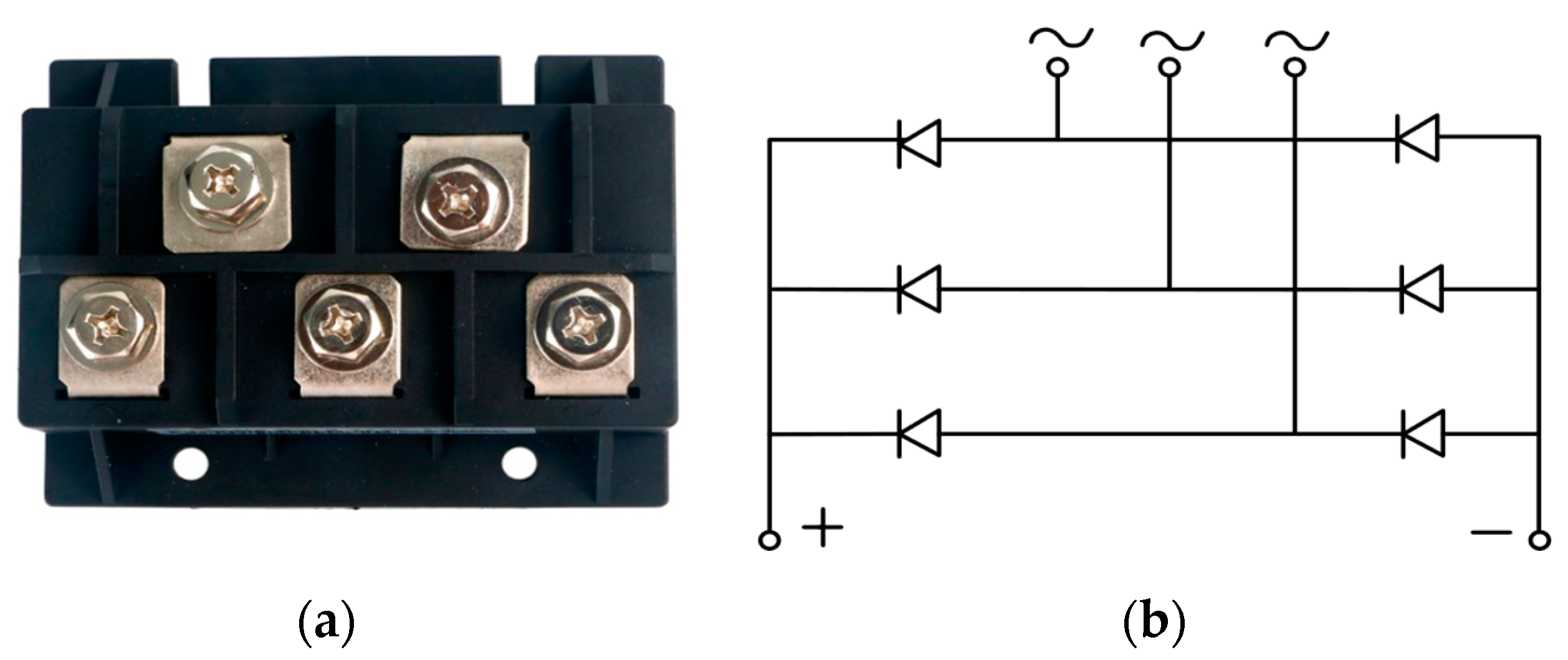
The rectifier, as shown in Figure 10, has been selected for this paper, together with a circuit diagram illustrating the rectifier’s operational principles.
The operating parameters of the rectifier selected in this paper are shown in Table 3. As an indispensable working component, the rectifier should be selected to meet the requirements of the current generated by the permanent magnet synchronous motor, and at the same time it should be both miniaturized and lightweight. From the performance of the actual test flight situation, the rectifier meets the above requirements well.

3.5. Thrust Propulsion Design

In the improved series hybrid power architecture, the load can be divided into three components. The first component is the VPP, which provides frontal thrust during level flight mode. The second component consists of four lift motor rotors. The final component comprises avionics devices such as the flight control unit and servo motors, among others. Compared to the first two components, the power consumption of avionics load is significantly lower and, hence, not considered in subsequent analysis.
In the vertical flight mode, the compound-wing VTOL can be regarded as a quadcopter, wherein the lift motor rotors generates lift force to counteract gravity. The stress conditions of the VTOL in this scenario can be mathematically represented by Equation (11).
C S W t o t a l × g + F d r a g = F l f
The W t o t a l is the total weight of the compound-wing VTOL and the F d r a g is the drag force of the VTOL by the air, which is needed to be overcome by the F l f provided by the lift motor rotors. The value of the drag force can be calculated by Equation (12).
F d r a g = 1 2 ρ ν C d , ν S ν V ν 2
The C s is a weighting factor that accounts for environmental disturbances during flight, such as wind. Its typical range of values is 115–125%. Additionally, due to the opposing direction of air resistance against the VTOL’s movement, the force F d r a g will be positive in the vertical-to-level transition mode and negative in the level-to-vertical transition mode.
In Equation (12), the ρ v is the air density, which is set to 1.293 kg/m3. The calculation does not consider the change in air density, as the VTOL operates at a relative flight altitude below 1000 m. C d is the drag coefficient and S v is the horizontal section of the VTOL in the take-off and landing program. The vertical-to-level and level-to-vertical modes are both programs designed for vertical movement, where V v represents the vertical velocity of the VTOL.
In the level flight mode, Equation (13) can be used to calculate the main pneumatic resistance. VPP serves as the level propulsion unit, with its primary objective being to provide a thrust range that covers the entire flight profile.
F d r a g = 1 2 ρ l C d , l S l V l 2
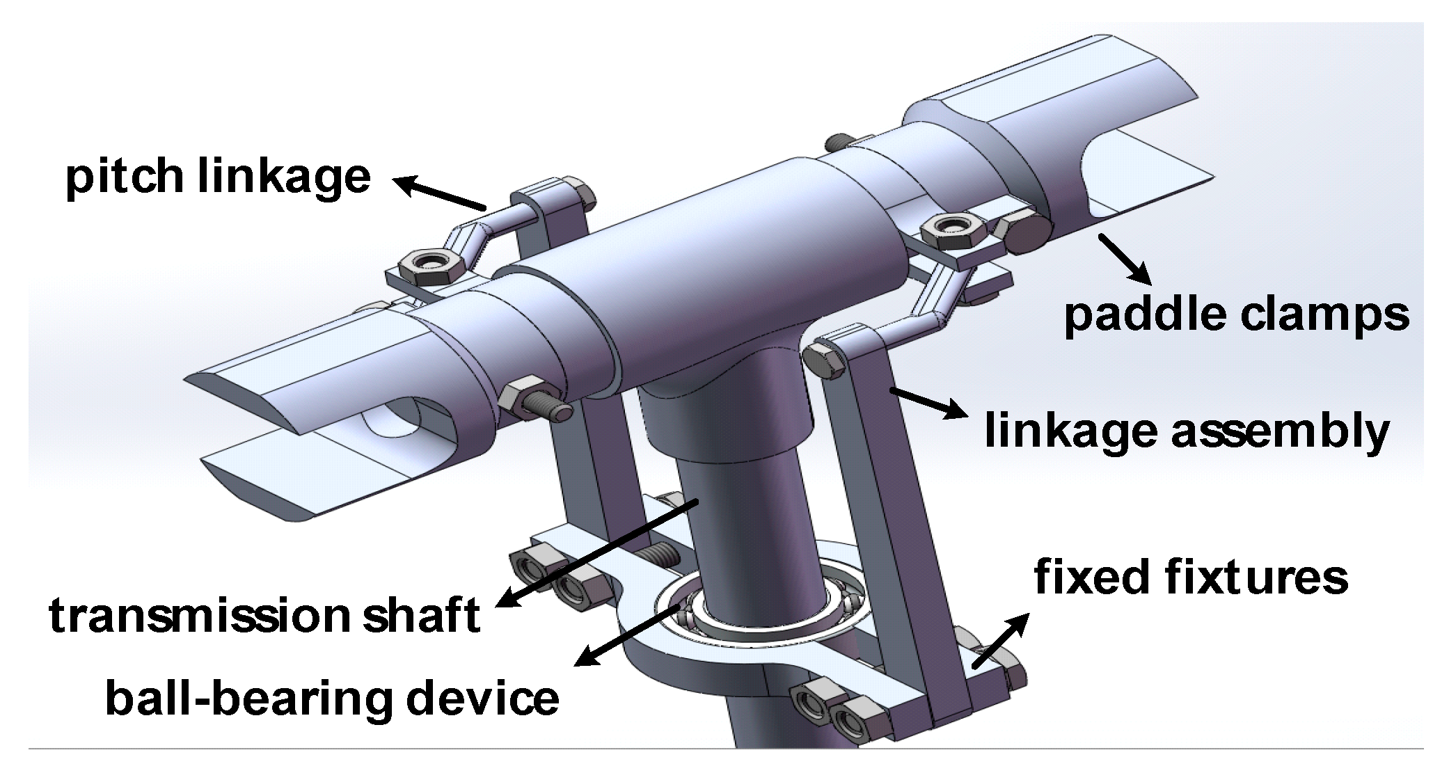
The layout of VPP is illustrated in Figure 11. Key considerations for the VPP include ICE performance factors such as power, gear ratio, and economic zone, as well as the number of blades, propeller radius, speed, and airspeed.
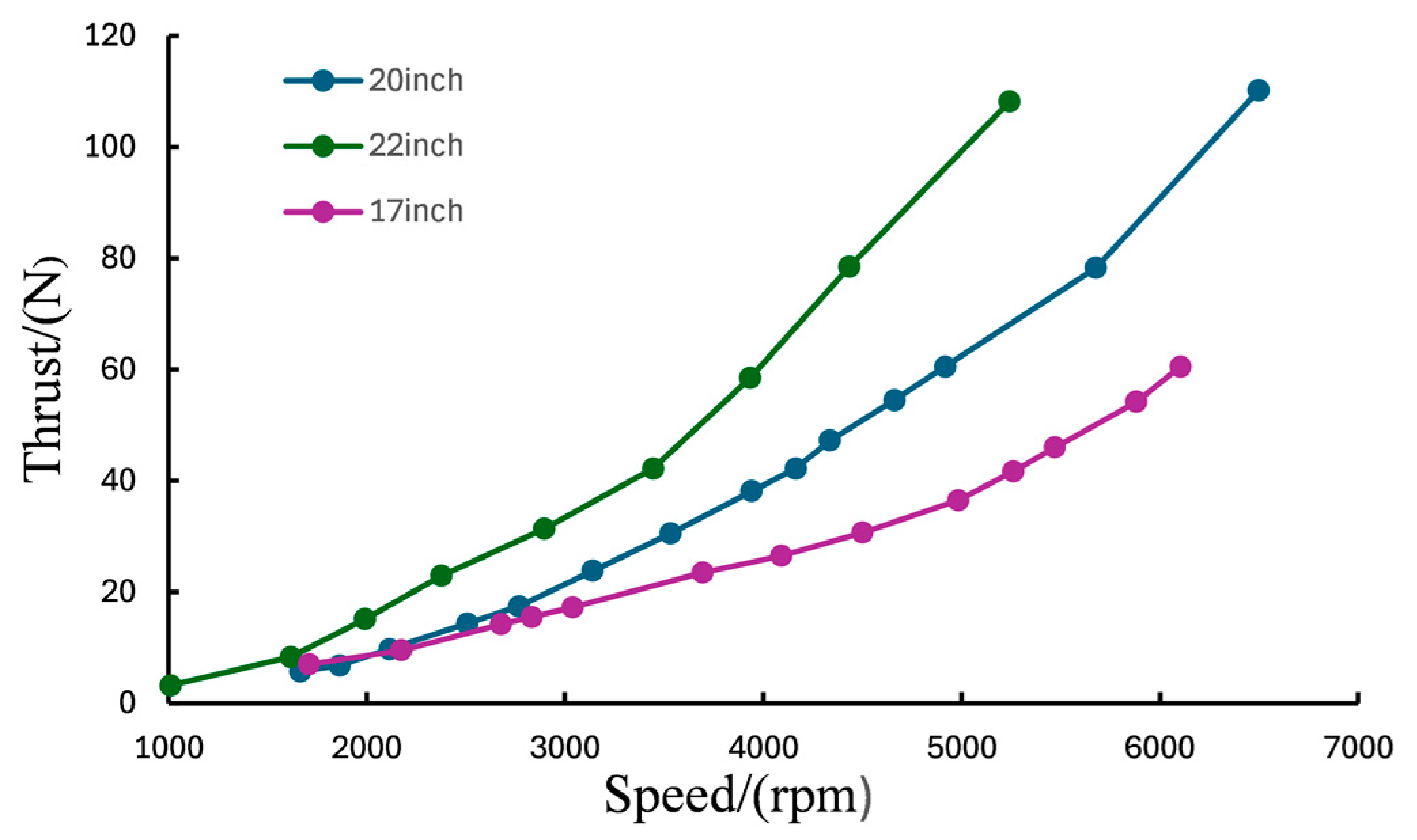
The addition of more propeller blades can decrease wind resistance and increase thrust, but it may also reduce the propeller’s efficiency due to increased turbulence. To determine the optimal size and number of blades for the VPP, a performance test comparing 17 inch, 20 inch, and 22 inch blades was conducted, as shown in Figure 12.
The results of previous experiments and studies demonstrate that the double-bladed VPP can meet the required thrust at a flow speed of 15 m/s. Therefore, as illustrated in Figure 12, the larger the propeller, the greater the thrust force produced for a given number of case revolutions. However, it should be noted that an increase in size will inevitably result in a proportional increase in weight. In conjunction with the optimal operating range of the internal combustion engine previously outlined, it can be seen that a 17-inch propeller at 6500 rpm will not satisfy the system requirement of at least 60 N of thrust force. Conversely, a 22-inch propeller at the same rpm will fulfil the system requirement, but will also result in an increase in weight within the actual system. A comparison of the data in the chart reveals that a 20-inch propeller represents the optimal solution, combining the advantages of both the 17-inch and the 22-inch models. In addition, the VPP’s pitch angle range is set between 9 degrees and 23 degrees to ensure the fulfillment of thrust requirements for typical flight missions.

4. Results

The improved series hybrid power architecture in the compound-wing VTOL, as mentioned above, is a sophisticated system with distinct characteristics. Given the risks associated with numerous high-speed rotational components and the volatility of fuel, it becomes imperative to construct a simulation model and conduct preliminary simulations before engaging in physical experimentation.

4.1. Hybrid Power System Simulation

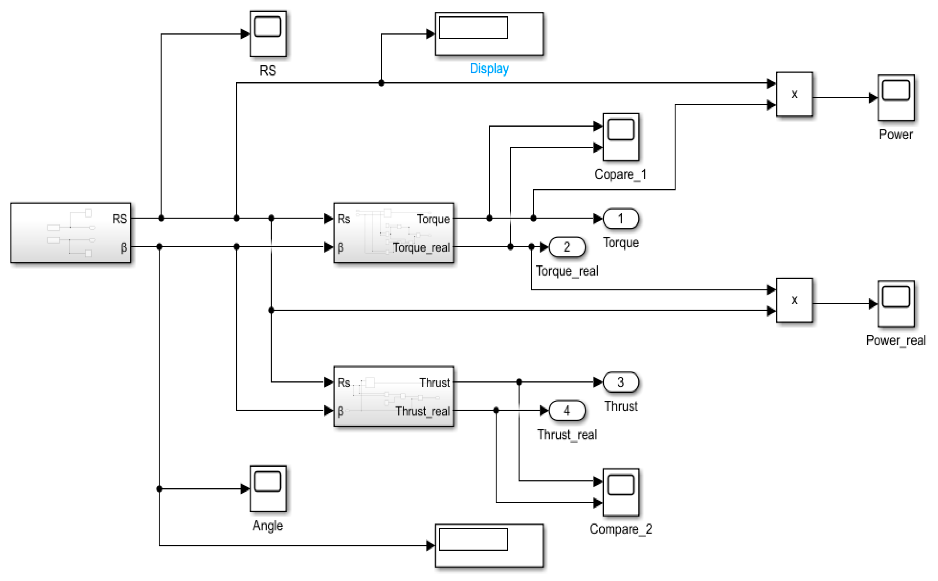
The performance of the VPP is significantly more intricate when compared to lift rotors. Due to the distinct working environment, the relationship between the power requirement and thrust output of the VPP cannot be simply described as linear. In the simulation of the VPP, there are two subsystems that calculate torque and thrust based on input signals such as rotational speed and pitch angle as depicted in Figure 13. In the two subsystems, in accordance with the blade-element theory, the propeller blade can be subdivided into discrete segments, and the force exerted on each segment can be analyzed. The tension and torque generated by the entire propeller can then be derived by integration. Nevertheless, the associated formulas are more intricate, necessitating the simplification of these formulas. This is due to the fact that the ratio of the blade vein chord length to the distance from the hub and the lift coefficient of the pitch propeller in the pitch propeller formulas are fixed values, while the air density remains an invariant constant within a certain range. Following numerous iterations of ground test data and the coefficient method, along with extensive verification, the simplified formula coefficients were approximated. It can be concluded that the thrust (T) and torque (M) are functions of the pitch angle and the number of revolutions of the paddle.
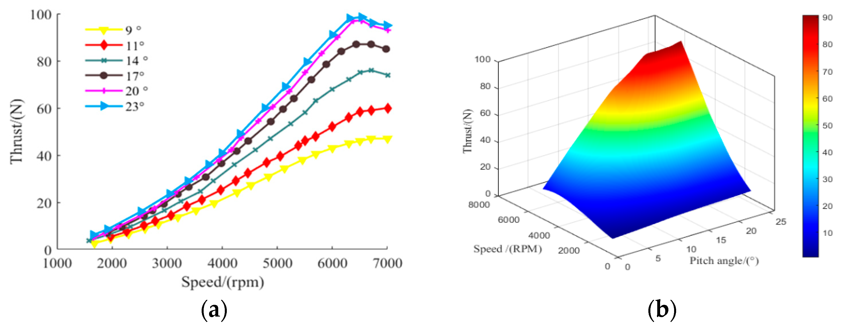
Based on the aforementioned calculation, the thrust required to maintain level flight mode remains at approximately 60 N. Additionally, the maximum thrust is attained during takeoff and climb, reaching around 96 N. Therefore, considering safety redundancy measures, it is recommended that the VPP be designed with a maximum thrust requirement exceeding 100 N. Furthermore, simulation results indicate that when the pitch angle is below 11 degrees, an increase in rotational speed leads to an augmentation in output thrust.
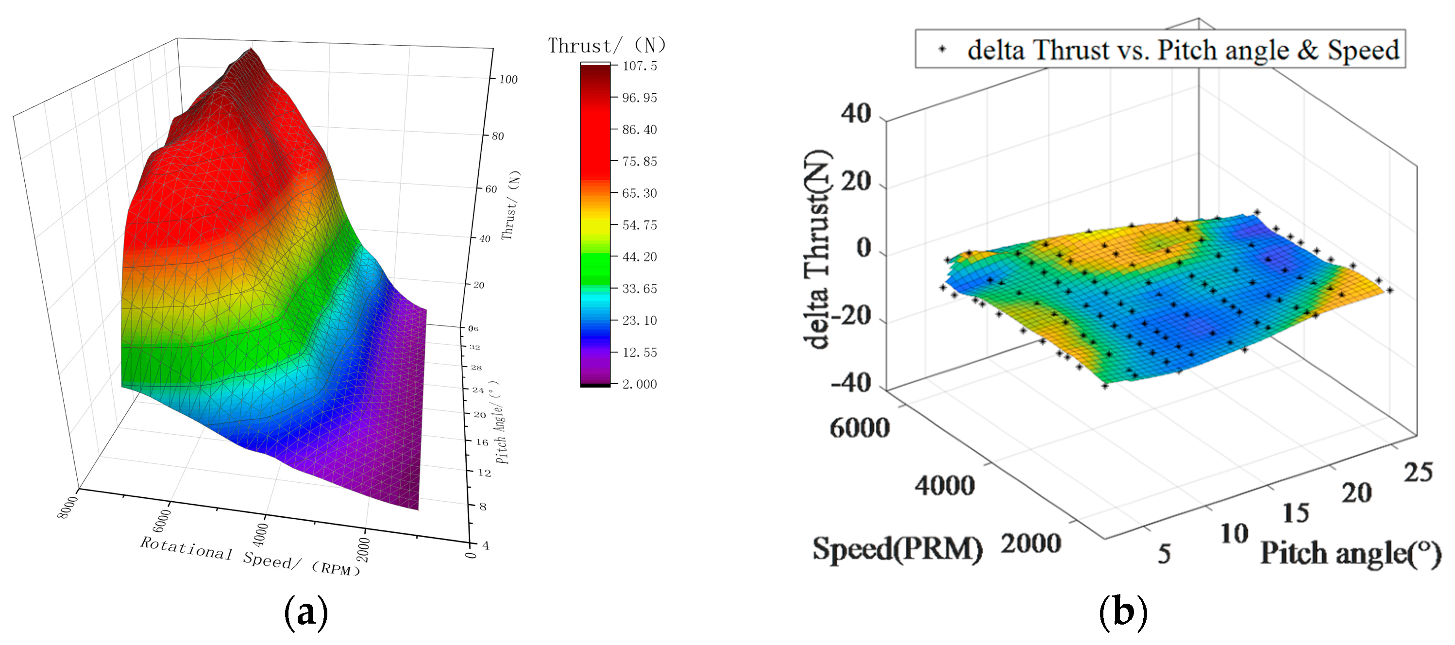
However, when the pitch angle exceeds 11 degrees, an increase in rotational speed leads to a significant thrust enhancement due to airflow separation and rapid wave effects. Under different pitch angles, a series of maximum thrust points occur at approximately 6500 RPM, as depicted in Figure 14. For the maximum number of revolutions and below 20 degrees and above 11 degrees, the pitch angle increases with the number of degrees, which can significantly increase the system thrust. However, when the pitch angle exceeds 20 degrees, the effect is greatly reduced. It can be seen that it is better to limit the pitch angle between 11 degrees and 23 degrees.
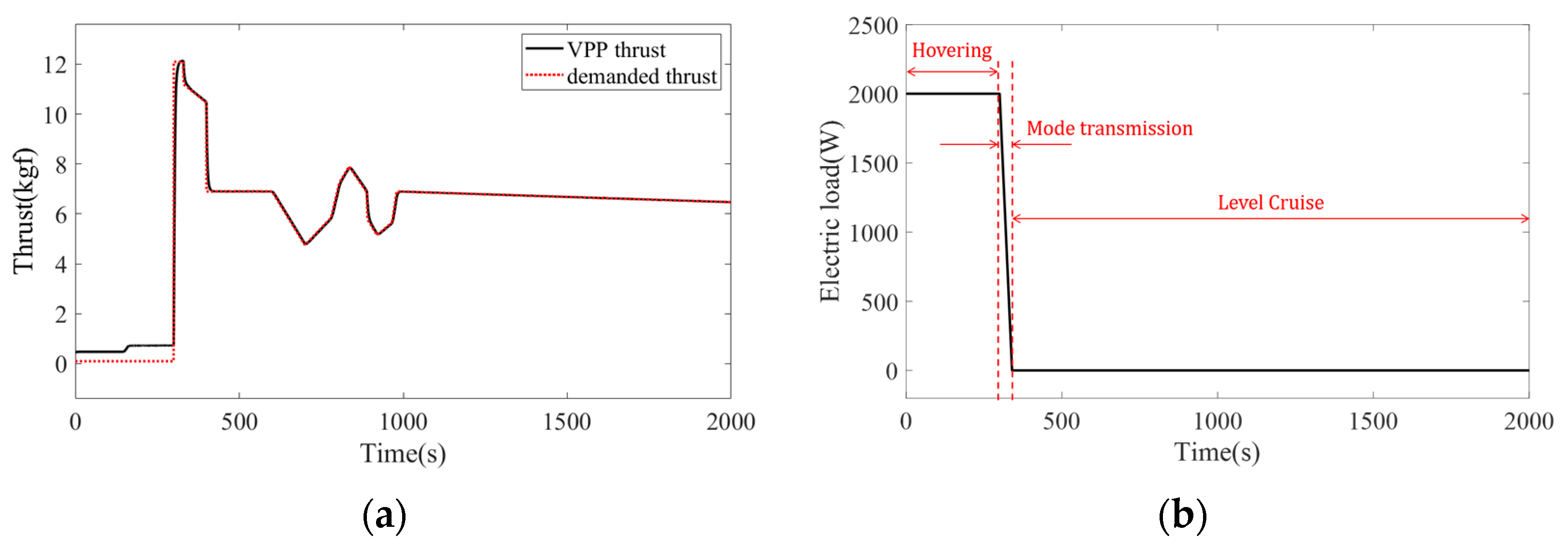
The simulation configuration is built following Figure 6; a typical flight profile starts with hovering, then followed by mode transition and level cruise flight. The thrust in Figure 15a initially starts at a low value under VPP’s low pitch to cool the ICE, then increases to a high value to facilitate the mode transition. The thrust from VPP is regulated to align with the demand during level flight. As depicted in Figure 15b, the electric load decreases when the rotors are deactivated during level cruise flight.
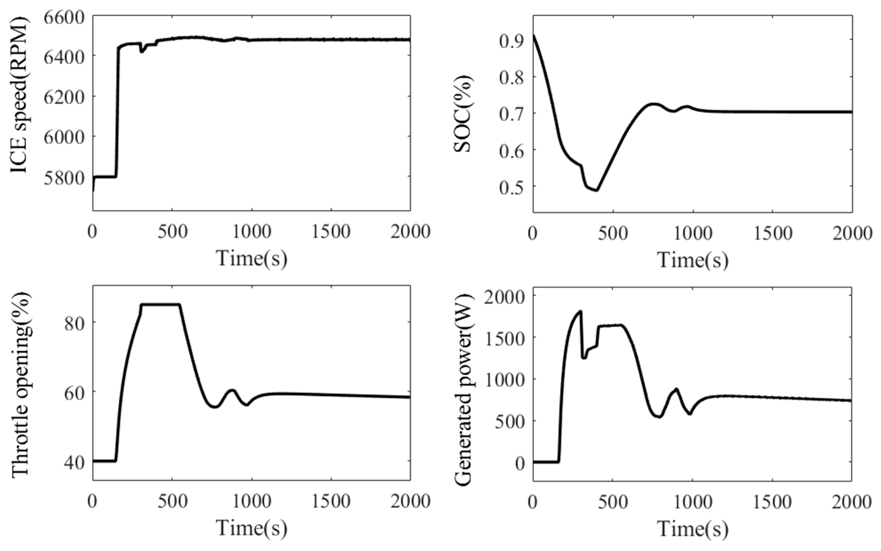
Some parameters undergo variations during the operation following the flight profile, as shown in Figure 16. As SOC falls under 70% (demanded), adjustments are made to increase throttle opening and ICE is controlled for acceleration. Simultaneously, the generator is optimized to generate maximum power in order to mitigate SOC decline until it approaches the demand.

4.2. Ground Test of Hybrid Power System

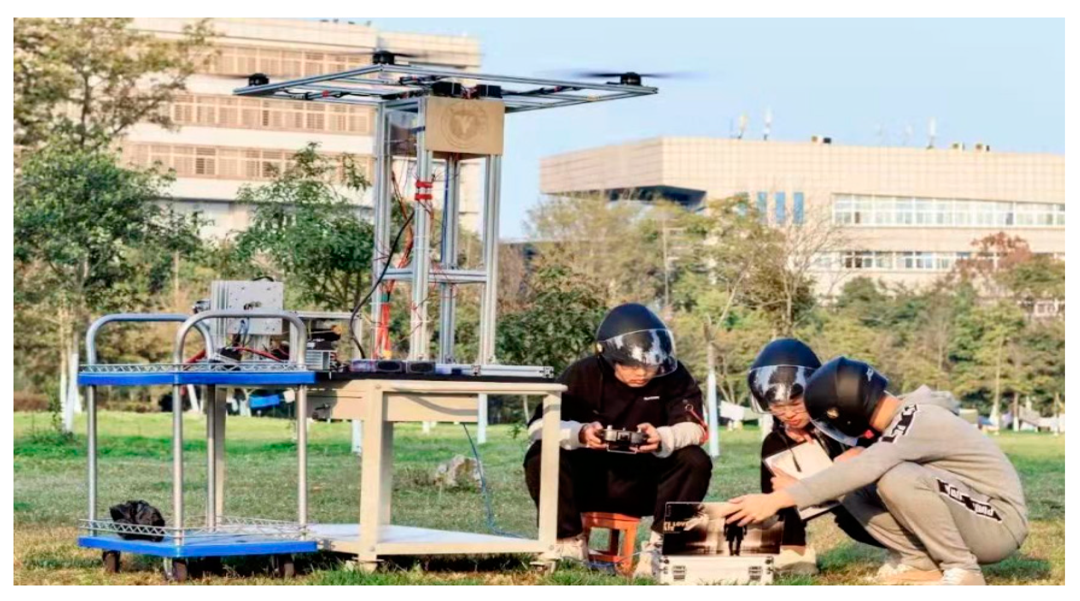
Before conducting the flight experiment of the improved series hybrid power architecture on the compound-wing VTOL, it is necessary to perform a ground performance experiment to verify the overall system stability. Therefore, a ground test bench has been assembled as depicted in Figure 17. Additionally, some parameters of the ground test bench are presented in Table 4.
The ground test bench features the same main structure as that installed on the compound-wing VTOL. The VPP, ICE, and PMSM are securely mounted on an aluminum frame, similar to their installation on the VTOL. The rectifier is connected to the PMSM and Li-Po battery package, ensuring stable installation on the bench. A rigid foursquare frame with a motor and 32-inch paddle at each vertex serves as the rotary subsystem of the VTOL. To monitor fuel consumption throughout the process, a fuel tank equipped with a weighting device is utilized. The throttle and load signals during ground testing perfectly mirror those set in the flight profile. Given that both experiment environments are grounded and configurations are similar, conducting ground experiments provides a safer means of assessing hybrid power system performance while facilitating faster implementation and verification of any design improvements or changes.
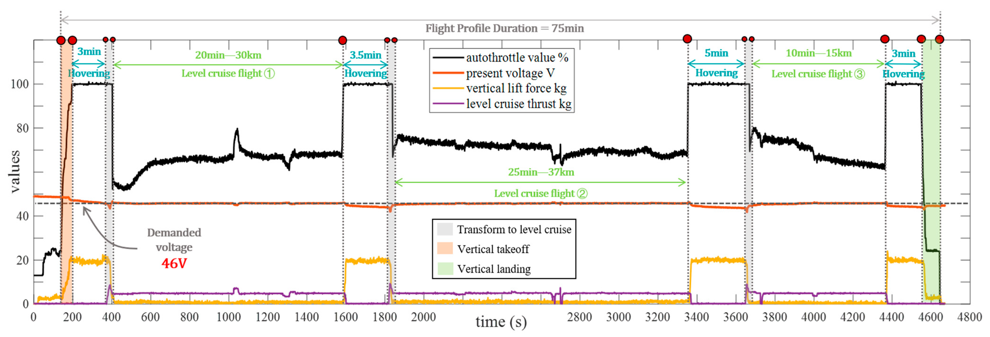
The endurance time and stability are two crucial standard test parameters in the performance experiment. The length of hovering endurance time, which serves as a fundamental indicator to validate the performance of the hybrid power system in the compound-wing VTOL, should be conducted initially. In hybrid compound-wing VTOLs equipped with a hybrid power system, the power requirement during hovering mode is typically higher than other modes. Therefore, conducting a hovering endurance experiment can also assess stability under heavy-load conditions. Some environmental parameters and settings for the hovering experiment are presented in Table 5, while Figure 18 illustrates the experimental setup. The data obtained from the ground test is displayed in Figure 19. As shown in Figure 19, three consecutive hover-to-level flight tests were successfully completed, and the total hover time was close to 15 min. When hovering, the system performs sub-optimally due to the need to counteract gravity, insufficient voltage (below 46 V) and maximum power output from the internal combustion engine. During level flight, the battery voltage serves as a reference point for adjusting the engine’s power output (as indicated by the autothrottle value percentage in the graph). After successfully transitioning to level flight for the first time, there is a sharp increase in autothrottle value accompanied by a drop-in system voltage below 46 V. Additionally, there is a peak in horizontal cruise thrust. In subsequent level flights, as battery charge exceeds 46 V, there is a gradual decrease in autothrottle value for the entire internal combustion engine along with an increase in level flight speed. These findings validate the feasibility of the hybrid power system.
Based on the aforementioned calculation, the lift rotors are set to provide a lift force of 22 kg, which corresponds to the typical total weight of the flight prototype. The VPP, positioned at a fixed angle, is installed in front of the ICE to facilitate cooling for both the ICE and PMSM. The total power required by the load exceeds 2.5 kW. Since this surpasses the maximum output power of the ICE for most of the experiment duration, a battery serves as an auxiliary power supply to bridge the energy gap between rotary requirements and PMSM operation. The results demonstrate that compared with an electrical configuration, utilizing hybrid compound-wing VTOL extends hovering endurance time from 5 min to over 25 min.
The load performance of the VPP can also be evaluated through ground testing, as depicted in Figure 20. Comparing Figure 20a with Figure 14, both show a gradual increase in the maximum system traction force as the pitch angle increases at 6500 rpm. On the other hand, Figure 20b shows the delta values of the ground experimental traction data and the digital simulation traction data, and the delta values do not show a large jerk. This is a direct indication of the high degree of agreement between the digital simulation created in the previous section and the actual system built. The test data of the ground experiment shown above verify that the hybrid system is reasonable and feasible from both the numerical simulation and physical experiment perspectives.

4.3. Hovering Endurance Flight Experiment

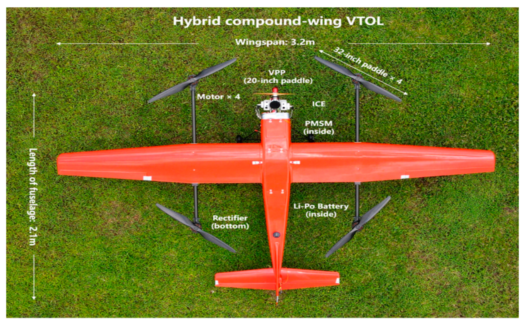
Based on the simulation results of the propulsion system and configuration topology, the first prototype is assembled, as depicted in Figure 21. The key parameters of the compound-wing VTOL are presented in Table 6. The ICE and PMSM are mounted on a fire-proof structure at the nose of the fuselage, while a 20-inch VPP installed in front of the ICE provides forward thrust during level flight mode. To ensure weight balance, a Li-Po battery and rectifier are integrated into the rear section of the fuselage. The entire hybrid power system is implemented on this VTOL prototype similar to its installation on the ground test bench, enabling flight testing.
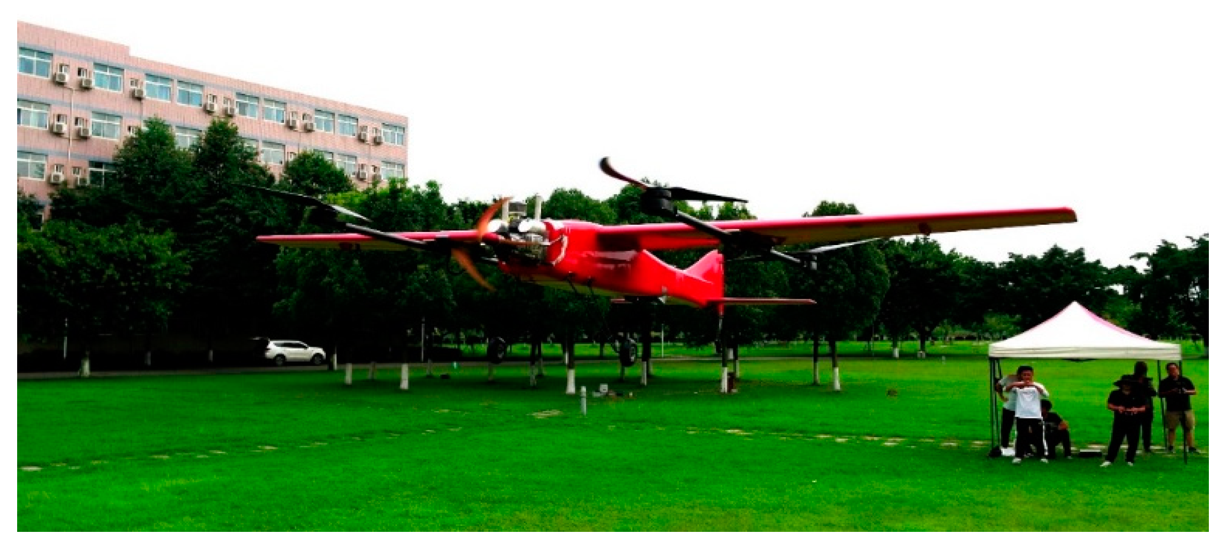
Based on the experimental results from ground experiments and the VTOL prototype, a flight experiment was conducted on the prototype. The results of the flight experiment are depicted in Figure 22.
These experimental findings are visualized in Figure 23. The provided figure depicts the power relationship among the motor, battery, and selected PMSM during the hovering test flight conducted in this paper. In the hybrid system, the power generated by the permanent magnet synchronous motor and the charging/discharging power of the battery are approximately equal to the load power of the motor. Throughout the hovering period, a constant level of load power is maintained for the motor. Whenever there is a need for battery-powered supply or charging within the system, it leads to a corresponding decrease or increase in power generated by the permanent magnet synchronous motor. This entire process has been demonstrated to last over 25 min, thereby confirming that this series hybrid system can fulfill multiple take-offs and landings as per target requirements. Moreover, this substantiates its applicability to this 25 kg compound-wing VTOL.

5. Conclusions

In order to augment the vertical flight endurance and optimize the compound-wing VTOL’s capacity for complex missions, the present paper introduces a design for a hybrid power system on compound-wing VTOL, comprising a variable pitch propeller, an internal combustion engine, a permanent magnet synchronous motor, a rectifier, a Li-Po battery, and a motor. The variable pitch propeller is driven by the internal combustion engine to generate forward thrust during horizontal flight phase. During vertical take-off and landing phase, the engine powers the permanent magnet synchronous motor to produce electricity, which is then rectified and combined with battery power to propel the aircraft during vertical take-off.
By incorporating a variable pitch propeller, it becomes feasible to maintain the internal combustion engine’s operation within the optimal range during both hovering and level flight, thereby enhancing fuel efficiency. The rationality of VPP was verified through comparison with both simulation and ground tests.
By implementing a dual-directional energy flow system in series, the aircraft is capable of achieving multiple take-offs and landings as well as extended hovering time. The feasibility was validated in a step-by-step manner through software simulations, ground tests, and flight tests. Based on the established mathematical model, simulations were conducted followed by the execution of the designated flight profile. The SOC was effectively replenished after hovering, while maintaining a consistent rotational speed of the ICE. Ground tests were performed based on a multi-destination flight profile, with a total hovering duration of 15 min and an approximate voltage remaining around 46 V. In the physical flight experiment, the integration of a hybrid power system enabled an extension in hover endurance time exceeding 25 min. Consequently, successful demonstration is achieved regarding the feasibility of implementing a series hybrid power system in a 25 kg compound-wing VTOL.
The findings of this study can serve as a reference and provide support for the power design of compound-wing aircrafts and UAVs. However, further investigation and study are necessary to enhance the reliability of this power system and identify the influencing factors, considering the limitations in terms of conducted experiments and available time.

Author Contributions

Conceptualization, S.A.; methodology, S.A.; software, S.A.; validation, M.D. and G.C.; formal analysis, M.D.; data curation, G.C.; writing—original draft preparation, S.A.; supervision, X.P.; project administration, S.A.; funding acquisition, X.P. and G.Y. All authors have read and agreed to the published version of the manuscript.

Funding

This work research was funded in part by Sichuan Provincial Science and Technology Plan Project foundation 2021YJ0064 and CAFUC science foundation under grants J2023-022, J2023-023 and CZKY2024031.

Data Availability Statement

In view of the fact that a substantial proportion of the data will also be employed to underpin future research, it has been decided that the data will not be made public.

Acknowledgments

The UAPL laboratory at the author’s university provided comprehensive support and oversaw the operations of this work. The dedicated colleagues and members in UAPL have made significant contributions to the development and experimentation of the VTOL.

Conflicts of Interest

The authors declare no conflicts of interest.

References

  1. Chen, H.B.; Lan, Y.B.; Fritz, B.K.; Hoffmann, W.C.; Liu, S. Review of agricultural spraying technologies for plant protection using unmanned aerial vehicle (UAV). Int. J. Agric. Biol. Eng. 2021, 14, 38–49. [Google Scholar] [CrossRef]
  2. Guan, S.Y.; Zhu, Z.; Wang, G. A Review on UAV-Based Remote Sensing Technologies for Construction and Civil Applications. Drones 2022, 6, 117. [Google Scholar] [CrossRef]
  3. Mangewa, L.J.; Ndakidemi, P.A.; Munishi, L.K. Integrating UAV Technology in an Ecological Monitoring System for Community Wildlife Management Areas in Tanzania. Sustainability 2019, 11, 6116. [Google Scholar] [CrossRef]
  4. Yang, Z.Y.; Yu, X.Y.; Dedman, S.; Rosso, M.; Zhu, J.; Yang, J.; Xia, Y.; Tian, Y.; Zhang, G.; Wang, J. UAV remote sensing applications in marine monitoring: Knowledge visualization and review. Sci. Total Environ. 2022, 838, 155939. [Google Scholar] [CrossRef] [PubMed]
  5. Granados-Bolanos, S.; Quesada-Roman, A.; Alvarado, G.E. Low-cost UAV applications in dynamic tropical volcanic landforms. J. Volcanol. Geotherm. Res. 2021, 410, 107143. [Google Scholar] [CrossRef]
  6. Ozdemir, U.; Aktas, Y.O.; Vuruskan, A.; Dereli, Y.; Tarhan, A.F.; Demirbag, K.; Erdem, A.; Kalaycioglu, G.D.; Ozkol, I.; Inalhan, G. Design of a Commercial Hybrid VTOL UAV System. J. Intell. Robot. Syst. 2014, 74, 371–393. [Google Scholar] [CrossRef]
  7. Wang, Y.; Zhu, H.; Zhao, Z.; Zhang, C.; Lan, Y. Modeling, System Measurements and Controller Investigation of a Small Battery-Powered Fixed-Wing UAV. Machines 2021, 9, 333. [Google Scholar] [CrossRef]
  8. Capello, E.; Scola, A.; Guglieri, G.; Quagliotti, F. Mini Quadrotor UAV: Design and Experiment. J. Aerosp. Eng. 2012, 25, 559–573. [Google Scholar] [CrossRef]
  9. Chiang, W.C.; Li, Y.Y.; Shang, J.; Urban, T.L. Impact of drone delivery on sustainability and cost: Realizing the UAV potential through vehicle routing optimization. Appl. Energy 2019, 242, 1164–1175. [Google Scholar] [CrossRef]
  10. Cao, J.; Anvar, A. Design, Modelling and Simulation of Maritime UAV-VTOL Flight Dynamics. Appl. Mech. Mater. 2012, 152–154, 1533–1538. [Google Scholar] [CrossRef]
  11. Cetinsoy, E.; Dikyar, S.; Hancer, C.; Oner, K.; Sirimoglu, E.; Unel, M.; Aksit, M. Design and construction of a novel quad tilt-wing UAV. Mechatronics 2012, 22, 723–745. [Google Scholar] [CrossRef]
  12. Cakir, H.; Kurtulus, D.F. Design and aerodynamic analysis of a VTOL tilt-wing UAV. Turk. J. Electr. Eng. Comput. Sci. 2022, 30, 767–784. [Google Scholar] [CrossRef]
  13. Czyba, R.; Lemanowicz, M.; Gorol, Z.; Kudala, T. Construction Prototyping, Flight Dynamics Modeling, and Aerodynamic Analysis of Hybrid VTOL Unmanned Aircraft. J. Adv. Transp. 2018, 2018, 7040531. [Google Scholar] [CrossRef]
  14. Zhang, B.W.; Song, Z.X.; Zhao, F.; Liu, C. Overview of Propulsion Systems for Unmanned Aerial Vehicles. Energies 2022, 15, 455. [Google Scholar] [CrossRef]
  15. Panigrahi, S.; Krishna, Y.S.S.; Thondiyath, A. Design, Analysis, and Testing of a Hybrid VTOL Tilt-Rotor UAV for Increased Endurance. Sensors 2021, 21, 5987. [Google Scholar] [CrossRef]
  16. Thibbotuwawa, A.; Nielsen, P.; Zbigniew, B.; Bocewicz, G. Energy Consumption in Unmanned Aerial Vehicles: A Review of Energy Consumption Models and Their Relation to the UAV Routing. Adv. Intell. Syst. Comput. 2019, 853, 173–184. [Google Scholar]
  17. Xiong, Z.J.; Xu, Y.M.; Wang, Z.Y.; Pian, X.; Wang, Y. Preliminary Design Method and Prototype Testing of a Novel Rotors Retractable Hybrid VTOL UAV. IEEE Access 2021, 9, 161141–161160. [Google Scholar] [CrossRef]
  18. Panagiotou, P.; Tsavlidis, I.; Yakinthos, K. Conceptual design of a hybrid solar MALE UAV. Aerosp. Sci. Technol. 2016, 53, 207–219. [Google Scholar] [CrossRef]
  19. Zong, J.A.; Zhu, B.J.; Hou, Z.X.; Yang, X.; Zhai, J. Evaluation and Comparison of Hybrid Wing VTOL UAV with Four Different Electric Propulsion Systems. Aerospace 2021, 8, 256. [Google Scholar] [CrossRef]
  20. Matlock, J.; Sharikov, P.; Warwick, S.; Richards, J.; Suleman, A. Evaluation of energy efficient propulsion technologies for unmanned aerial vehicles. Trans. Can. Soc. Mech. Eng. 2019, 43, 481–489. [Google Scholar] [CrossRef]
  21. Özbek, E.; Yalin, G.; Ekici, S.; Karakoc, T.H. Evaluation of design methodology, limitations, and iterations of a hydrogen fuelled hybrid fuel cell mini UAV. Energy 2020, 213, 118757. [Google Scholar] [CrossRef]
  22. Pugi, L.; Berzi, L.; Franchi, L.; Casazza, A.; Mattei, G.; Fiorenzan, R.; Domina, I. Preliminary Design and Simulation of an Hybrid-Parallel, Fixed-Wing UAV with Eight-Rotors VTOL System. In Proceedings of the 2022 IEEE International Conference on Environment and Electrical Engineering and 2022 IEEE Industrial and Commercial Power Systems Europe (EEEIC/I&CPS Europe), Prague, Czech Republic, 28 June–1 July 2022. [Google Scholar]
Figure 1. Two typical configurations of the UAV.
Drones 08 00634 g001
Figure 2. Typical multi-points flight mission profile.
Drones 08 00634 g002
Figure 3. (a) Typical configuration of the compound-wing VTOL; (b) 25 kg MTOW compound-wing VTOL prototype.
Drones 08 00634 g003
Figure 4. The improved series hybrid architecture and three different energy paths of the hybrid power system under different thrust modes. (a) The diagram illustrates the bidirectional flow path of energy throughout the hybrid system; (b) energy flow path in the full thrust mode, illustrates that in the case of vertical lift; (c) illustrates the energy flow path in cruise mode, in which the UAV is airborne; (d) energy flow path in the emergency thrust mode, shows the emergency mode.
Drones 08 00634 g004
Figure 5. Selecting or designing the five main components of the system, the second floor of the diagram shows the main factors to consider and the third floor shows the main system components.
Drones 08 00634 g005
Figure 6. (a) Piston ICE that drives a propeller in the cruise mode to provide the forward thrust for the aircraft. It also drives the PMSM to generate AC, which is passed through a rectifier to charge the batteries used in the drogue phase; (b) the Li-Po battery used in drones is designed as a single unit, usually a single unit with a voltage of 3.8 V to 4.2 V. The power system battery is made up of 12 pieces connected in parallel to ensure that the dropping voltage reaches 48 V and above.
Drones 08 00634 g006
Figure 7. (a) This is a multi-rotor brushless DC motor. It is DC powered to generate the upward lift; (b) this is a permanent magnet synchronous motor (PMSM), which is driven by an internal combustion engine for the generation of AC; (c) this is a three-phase bridge rectifier in the VTOL, which is a device that is used to convert AC to DC.
Drones 08 00634 g007
Figure 8. The general character map of the ICE.
Drones 08 00634 g008
Figure 9. The R-int model of battery.
Drones 08 00634 g009
Figure 10. (a) Shows five connections. The lower three interfaces in the diagram access the three-phase AC generated by the synchronous motor and the DC is connected via the upper two connectors; (b) shows the rectifier circuit working principle.
Drones 08 00634 g010
Figure 11. The schematic diagram of VPP.
Drones 08 00634 g011
Figure 12. The thrust performance of the 17-inch, 20-inch, and 22-inch propellers.
Drones 08 00634 g012
Figure 13. The simulation configuration of VPP.
Drones 08 00634 g013
Figure 14. (a) The output thrust character (2D) of VPP; (b) the output thrust character (3D) of VPP.
Drones 08 00634 g014
Figure 15. (a): Simulation thrust from VPP compared with demanded thrust; (b): simulation electric load that represents the lift on rotor.
Drones 08 00634 g015
Figure 16. Simulation of ICE rotational speed, SOC, throttle opening, and generated power versus time.
Drones 08 00634 g016
Figure 17. The specifically made ground test bench.
Drones 08 00634 g017
Figure 18. The ground experiment of the entire hybrid power system.
Drones 08 00634 g018
Figure 19. Flight profile data from ground experiment.
Drones 08 00634 g019
Figure 20. (a) The output thrust character of the VPP (ground experiment); (b) difference between measured data from the ground experiment and numerically simulated values.
Drones 08 00634 g020
Figure 21. The configuration of the hybrid compound-wing VTOL.
Drones 08 00634 g021
Figure 22. The hovering experiment of compound-wing VTOL.
Drones 08 00634 g022
Figure 23. The flight data based on the hovering experiment of compound-wing VTOL.
Drones 08 00634 g023
Table 1. The ICE’s parameters.
ItemParameter
Displacement60 mL
LayoutOpposed
Number of pistons2
Static thrust15.2 kg
CarburetorWapbro
Performance5 kW/8500 RPM
Compression ratio7:1
Diameter × Stroke36 mm × 30 mm
Weight1950 g
Lubrication ratio30:1
Spark plugNGK CM6
Table 2. The parameters of the PMSM.
ItemValue
Rated power2.5 kW
Number of modes3
Rated frequency1353 Hz
Rated voltage (mode to mode)48 V
Connection typeConnection
Number of slots/pole pairs24/14
Diameter of armature101.2 mm
Length of iron core47 mm
Dimension of NdFe3542 mm × 20 mm × 4 mm
Table 3. The parameters of the rectifier.
Item Value
Reverse repetitive maximum voltage600–200 V
Reverse unrepeated maximum voltage1700 V
DC output current150 A
Forward surge current1500 A
Surge current squared time product11,400 A2S
Threshold voltage0.8 V
Slope resistance3.8 mΩ
Forward maximum voltage1.5 V
Isolation voltage2500 V
Storage temperature−40–125 °C
Weight425 g
Table 4. The parameters of ground test bench.
ItemParameter
Size1350 mm × 850 mm × 1950 mm
Weight92 kg
Type of communication2.4 GHz wireless
MonitorIntegrated industrial computer
Time between overhaul>30 working hours
Table 5. The hovering experiment parameters.
ItemParameter
Temperature30 °C
Altitude>450 m (QNE)
Wind rating>8 m/s
Humidity60%
MTOW25 kg
Cooling typeAir cooling
Table 6. The compound-wing VTOL basic parameters.
ItemParameter
Wingspan3.2 m
Total length2.1 m
MTOW25 kg
Fuselage weight<19 kg
Battery capacity5200 mAH
Connection type of cells12S1P
Size of rotary paddle32 inches
Size of VPP’s paddle20 inches
Disclaimer/Publisher’s Note: The statements, opinions and data contained in all publications are solely those of the individual author(s) and contributor(s) and not of MDPI and/or the editor(s). MDPI and/or the editor(s) disclaim responsibility for any injury to people or property resulting from any ideas, methods, instructions or products referred to in the content.