Article

Performance Analysis of UAV RF/FSO Co-Operative Communication Network with Co-Channel Interference

Information and Navigation College, Air Force Engineering University, Xi’an 710077, China
*
Author to whom correspondence should be addressed.
Drones 2024, 8(3), 70; https://doi.org/10.3390/drones8030070
Submission received: 23 January 2024 / Revised: 17 February 2024 / Accepted: 19 February 2024 / Published: 20 February 2024

Abstract

:
The unmanned aerial vehicle (UAV) communication network has emerged as a promising paradigm capable of independent operation and as a relay to enhance communication coverage and efficiency. However, densely distributed terrestrial base stations with shared communication frequencies inevitably generate co-channel interference (CCI). The interference effect can be effectively eliminated by implementing free-space optical (FSO) communication in the UAV communication network. This paper proposes a solution for the UAV communication network to address interference effectively, specifically by employing a hybrid millimeter-wave radio frequency (RF)/FSO communication system. The RF links serve as the primary means of communication, while the FSO links act as a backup means of communication in the case of CCI. The exact outage probability (OP) and average symbol error rate (SER) expressions are derived for the hybrid RF/FSO communication network. The decision to switch between them depends on the signal-to-interference-plus-noise ratio (SINR). Furthermore, the SINR switching threshold value, which satisfies the target SER, has been calculated numerically for the proposed model. Simulation results indicate that the proposed network notably enhances the OP and attains a signal-to-noise ratio gain of approximately 4.6 dB in the average SER, particularly in scenarios where the RF links are subjected to severe interference or adverse weather conditions, as opposed to a pure RF communication network.

1. Introduction

1.1. Background

As an emerging technology, unmanned aerial vehicles (UAVs) are penetrating various fields such as courier transport, area reconnaissance [1,2], disaster search and rescue [3], and smart agriculture, as a result of their small size, low operation and maintenance costs, and low operational hazards [4]. By aggregating UAVs with different functions, the UAV communication network supported by artificial intelligence and big data is developing with a high degree of autonomous control, decision-making, and learning capabilities, and this has become a mainstream trend for future development [5]. However, interference is becoming increasingly prominent among UAV communication’s significant challenges. Since the main frequency range utilized for UAVs falls within the microwave spectrum, typically ranging from 300 MHz to 3000 GHz, there is overlap with the mobile communication band. The transmitted signals are inevitably interfered with by base stations, especially in communication-intensive areas. As the interference signals intensify, the UAV’s received signals will be seriously degraded, resulting in a substantial increase in the packet loss probability and bit error rate (BER) of the transmitted data. Thus, it negatively impacts the effective range of information communication and, in severe cases, results in a loss of connection among the UAVs. Therefore, improving the reliability of UAV communication has become a pressing issue [6].
Traditional anti-interference methods, such as the sequence-based frequency hopping spread spectrum (FHSS) and direct sequence spread spectrum (DSSS), are unable to adapt to dynamic spectral states and interference patterns due to their preset and fixed transmission patterns [7]. Millimeter-wave radio frequency (MMW RF)/free-space optical (FSO) co-operative communication provides a new concept with which to improve the anti-interference capability of UAV communication networks. Compared to MMW RF communication, FSO communication offers advantages such as high security, license-free spectrum, and immunity to electromagnetic interference [8]. FSO can serve as a backup option for RF communication, effectively countering strong electromagnetic interference while meeting high-speed and large bandwidth transmission requirements. FSO and MMW RF also exhibit differences in the impact of weather conditions on communication, with MMW RF communication (around 60 GHz band) being sensitive to oxygen absorption and rain. In contrast, FSO communication is highly susceptible to fog [9]. Co-operative communication based on FSO and MMW RF means can alleviate the drawbacks of homogeneous communication methods and improve the rate and reliability of communication by fully exploiting their complementary characteristics.

1.2. Related Works

Currently, the co-operative form of two communication means can be classified into two categories: the mixed RF/FSO communication system and hybrid RF/FSO communication system [10]. A mixed RF/FSO communication system can effectively enhance communication coverage, typically using FSO to address the last-mile access issue between users and core networks. In [11,12,13,14,15,16], the detailed performance analysis is presented for the mixed RF/FSO communication system under interference. The performance of a mixed RF/FSO communication system using amplify-and-forward (AF) relaying is analyzed in [11,12], where the received RF signals are affected by co-channel interference (CCI). Closed-form expressions for the system’s outage probability (OP) and bit error probability (BEP) are derived in [13] under the assumption that the effect of CCI is considered at both the relay and destination. In addition, ref. [14] presents the OP, average BER, and outage capacity of a two-way mixed RF/FSO communication system. Distinguished from the single-relay communication model, the performance of a multi-branch dual-hop (DH) system is investigated, considering both CCI and self-interference at the relay [15]. A mixed RF/FSO communication system with multiple branches/relays under the effects of CCI has been investigated in [16]. Research on mixed RF/FSO communication systems has focused on analyzing system performance based on various system and channel models.
The research on hybrid RF/FSO communication systems focuses on the co-operation mechanisms of the two communication means, broadly categorized as hard and soft switching. The hard-switching mechanism operates on the principle that only one mean is active at a time [17,18,19,20,21], while the soft-switching mechanism requires the joint coding of RF and FSO signals [22,23]. Hard-switching has garnered more attention due to its straightforward structure and easy implementation. The performance of a hybrid RF/FSO communication system in both single-threshold and double-threshold cases, including OP, average BER, and ergodic capacity (EC), has been analyzed in [17]. A new switching scheme is proposed [18], in which a single threshold is set for RF communication while a double threshold is set for FSO communication. Closed-form expressions for the OP and BER of the system are derived. Unlike the single-link structure described above, the OP and EC of a multi-hop (MH) hybrid RF/FSO communication system with a decode-and-forward (DF) scheme for relaying were analyzed in [19]. The results indicated that the MH hybrid communication system can handle adverse weather conditions and strong pointing errors. A selective DF scheme is proposed in [20], and the performance (OP and average symbol error rate (SER)) of a hybrid RF/FSO communication system, which includes both direct and DH links, is analyzed. A hybrid RF/FSO communication system typically uses RF communication as a backup means to overcome the effects of atmospheric turbulence and other factors on the FSO links. In summary, Table 1 provides a broad overview of the mixed and hybrid FSO/RF systems research, including channel modeling details.

1.3. Motivations and Contributions

The dense distribution of base stations and limited RF communication bands create the potential for interference to impact the performance of multiple links simultaneously. Compared with the mixed RF/FSO communication system, the hybrid RF/FSO communication system can effectively deal with communication interference. To the best of the authors’ knowledge, current research focuses on terrestrial networks, using FSO communication as the preferred means of communication and switching the means of communication according to a predetermined signal-to-noise ratio (SNR) threshold. Nevertheless, the high-frequency vibration of UAVs presents a challenge to the acquisition, tracking, and pointing (ATP) of FSO communication. It is feasible to realize FSO communication between UAVs through advances in visual-tracking and beam-tracking technologies. However, the link reliability is relatively low compared to the realization of MMW RF communication based on multiple-input-multiple-output techniques, and thus, FSO communication is more suitable for emergencies. Motivated by this, the main contributions of our work are summarized as follows:
  • In contrast to most of the literature, oriented toward single-hop models, we propose an MMW RF/FSO communication network model that includes three nodes. The proposed model comprises direct and DH links, employing a selective DF scheme for the relay. The multi-node model aligns better with the characteristics of the UAV network as a centerless, self-organized network.
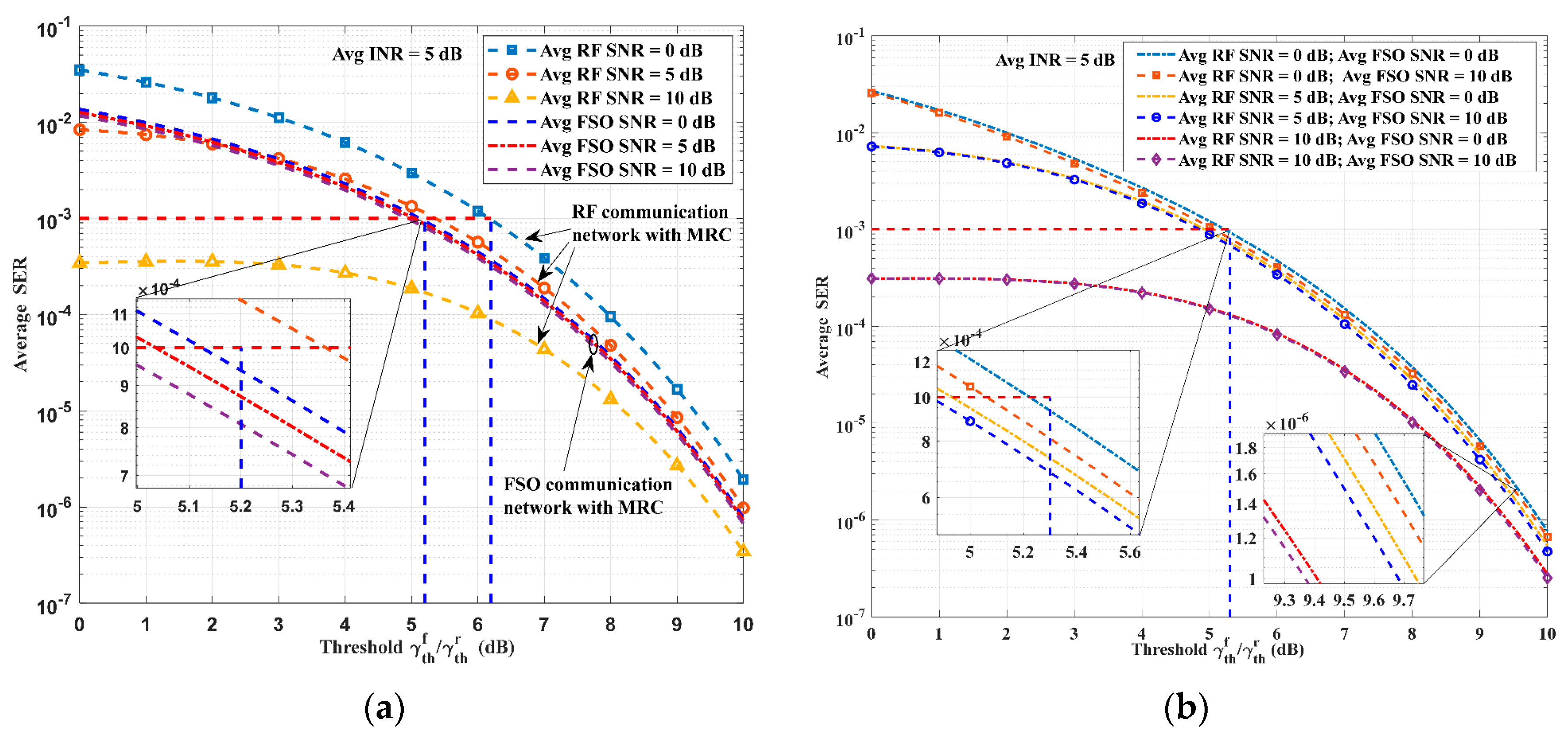
  • We propose the ideal switching signal-to-interference-plus-noise ratio (SINR) values by plotting the average SER with respect to SINR threshold values. The ideal value is chosen to satisfy the target average SER value. The SINR value is determined based on the worst-case scenario to ensure it can fulfill communication requirements across different interference levels.
  • We derive closed-form expressions for the OP and the average SER for the hybrid MMW RF/FSO communication network in the presence of CCI. RF and FSO links are analyzed using Nakagami-m and Μalaga models, respectively. Additionally, path loss and pointing error factors are considered, enhancing the models’ overall applicability. The exact expressions were verified using the Monte Carlo method.
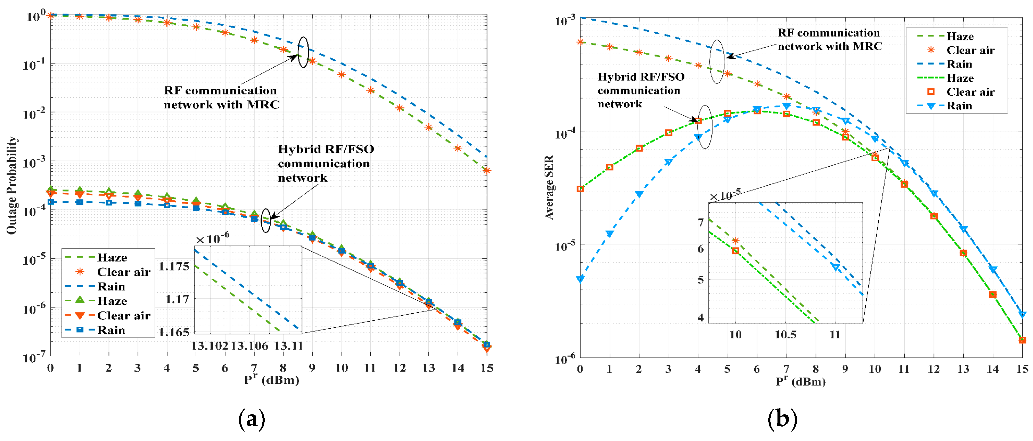
  • We evaluated the effectiveness of a hybrid MMW RF/FSO communication network under various levels of interference, weather conditions, and turbulence. The simulation results indicate that the hybrid network can significantly improve overall performance when the RF link quality is less than optimal compared to a pure RF communication network.
The remaining parts of the paper are divided into six sections. Section 2 describes the network and channel models of MMW RF and FSO links. Additionally, the statistical characteristics of these links are presented in this section. Section 3 and Section 4 analyze the OP and average SER of the hybrid RF/FSO co-operative communication network, respectively. Additionally, we derive closed-form expressions for each performance metric. Section 5 is dedicated to discussing the numerical results, followed by concluding remarks and an outlook in Section 6.

2. Network and Channel Models

The switching-based UAV MMW RF/FSO co-operative communication network is shown in Figure 1. The proposed model consists of a source (S), a relay (R), a destination (D), and interferers ( I l ), l = 1 , 2 , , L , where L denotes the number of interferers. The relay uses a selective DF scheme which only forwards signals if it decodes the received signals successfully [24]. In addition, the destination combines the two-phase received signals obtained through the S-D and R-D links applying maximum-ratio combining (MRC). Both the relay and the destination are subjected to CCI.
The mechanism of switching between MMW RF and FSO links among UAVs is illustrated in Figure 2. As for the RF/FSO co-operative communication network, UAVs transmit information over MMW RF links when the instantaneous SINR at D exceeds the threshold γ t h r . If the instantaneous SINR deteriorates, the FSO transmission is activated using a single-bit feedback signal. When the RF links become available for communication, the system will resume using them to maintain communication. In other words, only one means is active at a time. Moreover, if the instantaneous SNR of the FSO links at D drops below the threshold γ t h f , the co-operative communication network experiences an outage.

2.1. MMW RF Channel Model

For the case of MMW RF links, the received signals at R and D can be represented separately as follows:
S R   link : y S R r = P S R r g S R r h S R r x r + l = 1 L P l I g l R I h l R I s l + n S R r S D   link : y S D r = P S D r g S D r h S D r x r + l = 1 L P l I g l D I h l D I s l + n S D r R D   link : y R D r = P R D r g R D r h R D r x r ^ + l = 1 L P l I g l D I h l D I s l + n R D r
where P j r , j { S R , S D , R D } , and P l I are the transmitted powers of the source, relay, and l t h interferer, respectively; n j r is the additive white Gaussian noise (AWGN) with zero mean and variance σ r 2 ; h j r and h z I , z { l R , l D } are the channel gains of the MMW RF links, which are modeled using Nakagami-m distribution. This means both desired and interfering signals suffer from quasi-static flat Nakagami fading. g j r and g z I denote the average power gains of the RF links, calculated specifically as follows [25]:
g = G t + G r 20 log 10 ( 4 π L j / λ r ) ( α o x y + α r a i n ) L j
where G t and G r are the transmit and receive antenna gains, respectively; λ r is the wavelength of MMW RF signals; L j is the distance between the transmitter and the receiver; and α o x and α r a i n denote the attenuation caused by oxygen absorption and rain, separately. In addition, x r , x r ^ , and s l are the transmitted symbols with unit power, respectively.
The instantaneous SNR γ j r and the average SNR γ j r ¯ of the links for the desired signals are, respectively, given by:
γ j r = γ j r ¯ | h j r | 2 ,   γ j r ¯ = P j r g j r / σ r 2
Since the channel gains of fading links h j r have a Nakagami-m distribution with fading severity factor m j r , | h j r | 2 undergoes a Gamma distribution with E [ | h j r | 2 ] = Ω j r , where E [ · ] is the expectation operator. The probability density function (PDF) of γ j r for a single-hop link is given by:
f γ j r ( γ r ) = ( ω j r γ j r ¯ ) m j r ( γ r ) m j r 1 Γ ( m j r ) exp ( ω j r γ r γ j r ¯ ) ,   ω j r = m j r / Ω j r
where Γ ( · ) is the Gamma function. Similarly, the PDF of the instantaneous interference-to-noise ratio (INR) γ z I for a single-hop interference link is:
f γ z I ( γ I ) = ( ω z I γ z I ¯ ) m z I ( γ I ) m z I 1 Γ ( m z I ) exp ( ω z I γ I γ z I ¯ ) , ω z I = m z I / Ω z I
where γ z I = γ z I ¯ | h z I | 2 and γ z I ¯ = P l I g z I / σ r 2 denote instantaneous INR and average INR, respectively.

2.2. FSO Channel Model

We are assumed to adopt subcarrier intensity modulation/direct detection (IM/DD) for the FSO links. For the case of FSO links, the received signals at R and D can be given separately by:
S R   link : y S R f = η P S R f h S R f x f + n S R f S D   link : y S D f = η P S D f h S D f x f + n S D f R D   link : y R D f = η P R D f h R D f x f ^ + n R D f
where η is the optical-to-electrical conversion coefficient; P j f is the optical power transmitted by the source or relay; n j f denotes the AWGN with zero mean and variance σ f 2 ; and x f and x f ^ are the transmitted symbols with unit power. The FSO links’ channel gains h j f are modeled using a generalized Malaga distribution with pointing errors and path loss. Therefore, the channel gain h j f can be expressed as follows: h j f = h j a h j l h j p , where h j a , h j l , and h j p represent the atmospheric turbulence, path loss, and pointing errors, respectively. Due to the generality of the Malaga turbulence model [26,27], the atmospheric turbulence-induced fading h j a is assumed to follow the generalized Malaga distribution. Based on the determined weather conditions, the path loss h j l is constant, given by h j l = exp ( α w L j ) , where α w is the weather-related attenuation coefficient [23]. Furthermore, the high-frequency vibration of the UAV can cause misalignment r = X 2 + Y 2 between the beam and the detector center, resulting in signal attenuation at the receiver. It is assumed that the displacement along the horizontal and elevation axis is a Gaussian random variable with mean and variance of 0 and σ u 2 [28].
The instantaneous SNR γ j f and the average SNR γ j f ¯ at the output of the FSO receiver are given by:
γ j f = η 2 ( P j f ) 2 | h j f | 2 / σ f 2 ,   γ j f ¯ = η 2 ( P j f ) 2 E [ | h j f | ] 2 / σ f 2
where E [ | h j f | ] = A 0 , j h l ς j 2 ( p j + Ω j * ) / ( 1 + ς j 2 ) . The PDF of γ j f is:
f γ j f ( γ f ) = ς j 2 A j 4 γ f m = 1 β j b j , m G 1 , 3 3 , 0 ( κ j γ f γ j f ¯ | ς j 2 + 1 ς j 2 , α j , m )
where:
A j = 2 α j α j / 2 p j 1 + α j / 2 Γ ( α j ) ( p j β j p j β j + Ω j * ) β j + α j / 2 ,   κ j = ς j 2 α j β j ( p j + Ω j * ) ( 1 + ς j 2 ) ( p j β j + Ω j * ) b j , m = ( β j 1 m 1 ) ( p j β j + Ω j * ) 1 + α j / 2 ( m 1 ) ! ( Ω j * p j ) m 1 ( α j ) α j / 2 ( β j ) ( α j / 2 + m )
G p   q m   n ( · ) denotes the Meijer G-function [29], and the remaining parameters are given in Table 2.

3. Outage Probability Analysis

Concerning a pure MMW RF or FSO communication network, the network encounters an outage when the instantaneous SINR/SNR at D after MRC falls below a predetermined threshold. However, the MMW RF/FSO co-operative communication network will experience a communication outage when both communication means are unable to reach the threshold value. Thus, the expression for the outage probability of the RF/FSO co-operative communication network is as follows:
P o u t = F γ M R C r ( γ t h r ) F γ M R C f ( γ t h f )
where F γ M R C r ( γ t h r ) and F γ M R C f ( γ t h f ) denote the cumulative distribution functions (CDFs) of the instantaneous SINR/SNR at D after MRC of the MMW RF and FSO links, respectively.

3.1. MMW RF Communication Subsystem

In the scenario where information is transmitted over MMW RF links, the instantaneous SINR γ M R C r of the received signals at the destination is given by:
γ M R C r = k P k l = 1 L P l D + σ r 2 = k γ k r l = 1 L γ l D I + 1 = γ S N R γ I N R + 1
where P k is the received power of the desired signals transmitted over the S-R-D or S-D link, while P l D is the received power of the interfering signals transmitted by the l t h interference, and γ S N R and γ I N R are the combined SNR and INR of all links, respectively.
The MMW RF links will encounter the outage under the condition that the output SINR at D falls below the threshold γ t h r . Therefore, the outage probability can be expressed as:
F γ M R C r ( γ t h r ) = 1 P [ γ S N R γ t h r ( γ I N R + 1 ) ] = 1 0 γ t h r ( γ I + 1 ) f γ I N R ( γ I ) f γ S N R ( γ r ) d γ r d γ I
The PDFs of the combined SNR f γ S N R ( γ r ) and combined INR f γ I N R ( γ I ) can be derived using the moment-generating function (MGF)-based approach. The MGF for the single link can be represented as:
M γ j r ( t ) = ( 1 α j r t ) m j r , α j r = γ j r ¯ / ω j r M γ z I ( t ) = ( 1 α z I t ) m z I , α z I = γ z I ¯ / ω z I
Assuming the links are mutually independent, the MGF of the combined SNR or INR is equal to the product of the individual MGF. For the MMW RF links, the PDF of the combined SNR can be obtained by using the inverse Laplace as follows:
f γ S N R ( γ r ) = 1 [ k M γ k r ( t ) ]
The relay can decode the signals successfully only if the SINR/SNR of the S-R link is greater than γ t h T , T { r , f } [24]. Therefore, whether it is MMW RF or FSO links, the PDF of the SINR/SNR of the signals transmitted over the S-R-D link f γ S R D T ( γ T ) is given by:
f γ S R D T ( γ T ) = F γ S R T ( γ t h T ) δ ( γ T ) + { 1 F γ S R T ( γ t h T ) } f γ R D T ( γ T )
where F γ S R T ( γ t h T ) denotes the probability that the relay fails to decode, and δ ( · ) is the impulse function. The MGF of f γ S R D r ( γ r ) can be expressed as:
M γ S R D r ( t ) = F γ S R r + ( 1 F γ S R r ) M γ R D r ( t )
Using Equation (16), the MGF of the combined SNR is given by:
k M γ k r ( t ) = F γ S R r M γ S D r ( t ) + ( 1 F γ S R r ) M γ S D r ( t ) M γ R D r ( t )
The product of the individual MGF can be represented as a sum of partial fractions as follows:
i = 1 N ( 1 α i t ) m i = i = 1 N j = 1 m i β i j ( t 1 / α i ) j
Its coefficients β i j can be determined by:
β i j = 1 ( m i j ) ! lim t ( 1 / α i ) { d m i j d t m i j [ ( t 1 α i ) m i ( k = 1 N ( 1 α k t ) m k ) ] }
The exact expression of β i j can be derived by:
β i j = ( 1 α i ) m i τ ( i , j ) k = 1 , k i N ( m k + q k 1 q k ) ( α k ) q k ( 1 α k / α i ) m k + q k
where τ ( i , j ) = { ( q 1 , q 2 , q N ) | k = 1 N q k = ( m i j ) ,   q i = 0 } is a set of N-dimensional vectors, and q k is a non-negative integer. Taking the inverse Laplace transform of the second half of Equation (17) expressed in the form of a series, we can obtain the following expression:
1 [ M γ S D r ( t ) M γ R D r ( t ) ] = μ = 1 2 ν = 1 m μ r ( 1 ) ν β μ ν r Γ ( ν ) ( γ r ) ν 1 exp ( γ r α μ r )
Moreover, the Laplace transform of M γ S D r ( t ) is exactly the PDF of γ S D r . Therefore, the PDF of the combined SNR can be obtained as:
f γ S N R ( γ r ) = F γ S R r ( γ t h r ) ( ω S D r γ S D r ¯ ) m S D r ( γ r ) m S D r 1 Γ ( m S D r ) exp ( ω S D r γ r γ S D r ¯ ) + ( 1 F γ S R r ( γ t h r ) ) μ = 1 2 ν = 1 m μ r ( 1 ) ν β μ ν r Γ ( ν ) ( γ r ) ν 1 exp ( γ r α μ r )
Since the interfering signals received by the destination are independent of each other, the derivation of f γ I N R ( γ I ) is similar to Equation (21), which is given by:
f γ I N R ( γ I ) = μ = 1 L ν = 1 m μ I ( 1 ) ν β μ ν I Γ ( ν ) ( γ I ) ν 1 exp ( γ I α μ I )
The expression for the SINR of the signals received by the relay is similar to Equation (11). The denominator part remains unchanged, representing the combined INR from L-interferers. However, the numerator part represents the SNR of the S-R link. Therefore, by substituting Equations (4) and (23) into (12), we can obtain F γ S R r ( γ t h r ) . Using [30], Equation (8.350.2), the inner integral can be expressed as the incomplete Gamma function. Then the remaining integral is solved by using [30], Equation (8.352.4), and [30], Equation (8.310.1), to obtain the exact expression as:
F γ S R r ( γ t h r ) = 1 μ = 1 L ν = 1 m μ I n = 0 m S R r 1 exp ( ω S R r γ t h r γ S R r ¯ ) ( ω S R r γ t h r γ S R r ¯ ) n ( 1 ) ν β μ ν I Γ ( n + 1 ) k = 0 n ( n k ) ( 1 α μ I + ω S R r γ t h r γ S R r ¯ ) ( ν + k ) Γ ( ν + k ) Γ ( ν )
The CDF of the instantaneous SINR γ M R C r at D after MRC can be obtained by substituting Equations (22) and (23) into (12). Using the derivation procedure consistent with F γ S R r ( γ t h r ) , we can obtain the closed expression as follows:
F γ M R C r ( γ t h r ) = 1 μ = 1 L ν = 1 m μ I ( 1 ) ν β μ ν I { F γ S R r ( γ t h r ) exp ( γ t h r ω S D r γ S D r ¯ ) a = 0 m S D r 1 ( γ t h r ω S D r γ S D r ¯ ) a 1 Γ ( a + 1 ) b = 0 a ( a b ) ( 1 α μ I + γ t h r ω S D r γ S D r ¯ ) ( b + ν ) Γ ( b + ν ) Γ ( ν ) + ( 1 F γ S R r ( γ t h r ) ) λ = 1 2 ρ = 1 m λ r ( 1 ) ρ β λ ρ r ( α λ r ) ρ exp ( γ t h r α λ r ) c = 0 ρ 1 ( γ t h r α λ r ) c 1 Γ ( c + 1 ) d = 0 c ( c d ) ( 1 α μ I + γ t h r α λ r ) ( d + ν ) Γ ( d + ν ) Γ ( ν ) }

3.2. FSO Communication Subsystem

If information is transmitted through FSO links, the CDF of γ M R C f is as follows:
F γ M R C f ( γ f ) = 0 γ f 0 γ f γ 2 f γ S R D f ( γ 1 ) f γ S D f ( γ 2 ) d γ 1 d γ 2
Substituting Equation (15) into (26) can give the following expression:
F γ M R C f ( γ f ) = F γ S R f ( γ t h f ) F γ S D f ( γ f ) + ( 1 F γ S R f ( γ t h f ) ) 0 γ f 0 γ f γ 2 f γ R D f ( γ 1 ) f γ S D f ( γ 2 ) d γ 1 d γ 2 F γ D f
Using Equation (8) and [29], Equation (07.34.21.0084.01), the CDF of γ j f for a single link is:
F γ j f ( γ f ) = ς j 2 A j 2 m = 1 β j b j , m G 2 , 4 3 , 1 ( κ j γ f γ j f ¯ | 1 , ς j 2 + 1 ς j 2 , α j , m , 0 )
For the second half of Equation (27), the inner integral can be solved using [29], Equation (07.34.21.0084.01), and the result can be further simplified using [31], Equation (6.11.1.1). Finally, the remaining integral is solved using [29], Equation (07.34.21.0084.01), to obtain the exact expression as follows:
F γ D f = m = 1 β R D n = 1 β S D A R D , m A S D , n b R D , m b S D , n c = 0 Γ ( 1 + ς R D 2 / 2 ) c ! G 3 , 7 6 , 1 ( κ R D 2 r f 16 γ R D f ¯ | 1 , ς R D 2 + 1 2 , ς R D 2 + 2 2 S 1 ) G 3 , 7 6 , 1 ( κ S D 2 r f 16 γ S D f ¯ | 1 c , ς S D 2 + 1 2 , ς S D 2 + 2 2 S 2 )
where A R D , m , A S D , n , S 1 , and S 2 are given in Table 3. Substituting Equations (28) and (29) into (27), we can obtain F γ M R C f ( γ t h f ) , and, substituting F γ M R C f ( γ t h f ) and F γ M R C r ( γ t h r ) into Equation (10), the outage probability of the UAV RF/FSO co-operative communication network is obtained.

4. Average SER Analysis

With regard to the UAV RF/FSO co-operative communication network, the calculation of the average SER is given by:
S E R ¯ M R C = B M R C r ( γ t h r ) + F γ M R C r ( γ t h r ) B M R C f ( γ t h f ) 1 P o u t
where B M R C r ( γ t h r ) and B M R C f ( γ t h f ) denote the average SER of the MMW RF and FSO links, respectively, under non-outage conditions. Therefore, B M R C T ( γ t h T ) can be expressed as:
B M R C T ( γ t h T ) = γ t h T p ( e | γ T ) f γ M R C T ( γ T ) d γ T
where p ( e | γ T ) = Q ( 2 γ T ) is the conditional SER based on the assumption that BPSK modulation is used for the transmitted data, and Q ( · ) denotes the Gaussian Q-function. Equation (31) can be expressed in CDF-based form, as follows:
B M R C T ( γ t h T ) = 1 2 2 π 2 γ t h T 1 γ T exp ( γ T 2 ) F γ M R C T ( γ T 2 ) d γ T B e , T F γ M R C T ( γ t h T ) Q ( 2 γ t h T )
The solution for B e , T is represented by Equation (33):
B e , T = 1 2 2 π 0 1 γ T exp ( γ T 2 ) F γ M R C T ( γ T 2 ) d γ T B e , T 1 2 2 π 0 2 γ t h T 1 γ T exp ( γ T 2 ) F γ M R C T ( γ T 2 ) d γ T B e , T γ
The F γ M R C T ( γ T / 2 ) can be calculated by replacing γ T / 2 with γ t h T in F γ M R C T ( γ t h T ) . By substituting F γ M R C T ( γ T / 2 ) into Equations (32) and (33), we can obtain B M R C r ( γ t h r ) and B M R C f ( γ t h f ) . Appendix A and Appendix B provide the closed expressions for B e , r and B e , f for the MMW RF and FSO links, respectively, along with the detailed derivation process. Substituting B M R C r ( γ t h r ) , B M R C f ( γ t h f ) , F γ M R C r ( γ t h r ) , and P o u t into Equation (30), the average SER of the UAV RF/FSO co-operative communication network is obtained.

5. Numerical Results and Discussions

In terms of the distance between UAVs, to mitigate the effects of long distances on FSO communications, it is assumed that L S R = L S D = L R D = 1   km . In addition, the distance from each interference to R or D is set to be approximately 5 km, based on realistic conditions. Without special remarks, the number of interferences defaults to one and the average INR of individual interference γ z I ¯ is set to 5 dB. We assume m j r = 3 , m z I = 2 , and Ω j r = Ω z I = 1 in the Nakagami-m distribution to model the fading of the MMW RF links. With respect to atmospheric turbulence in the FSO links, we assume the strong turbulence case ( C n 2 = 1 × 10 12 m 2 / 3 , α j = 2 , β j = 1 , and ρ j = 0.9 ). The values of FSO and RF parameters used in the simulations are given in Table 4. The summation limit parameter in Equation (29) and (A6) can be truncated to c = 50 and k = 50 without affecting the fifth decimal figure of the outage probability values. The convergence of the equations has been demonstrated in Appendix C. For all plots, we assume clear air as the default weather condition, unless otherwise specified.

5.1. SINR Switching Threshold

To determine the ideal SINR switching threshold value for the UAV RF/FSO co-operative communication network, we have analyzed the average SER of the pure RF and FSO networks through extensive simulations. Figure 3a shows the average SER performance versus the SINR/SNR threshold γ t h for different values of the average SNR of the RF and FSO links. It can be seen that the average SER is a decreasing function with respect to γ t h . There is no optimal switching threshold. Therefore, the SINR and SNR values that satisfy the target SER of 10 3 are selected as the RF subsystem switching threshold and FSO subsystem outage threshold, which are 6.2 dB and 5.2 dB, respectively. These values are obtained by considering the average SINR/SNR values corresponding to the worst-case performances of FSO and RF communication networks. In the case of an RF communication network, the average SER performance is analyzed under the three scenarios of strong interference ( γ r ¯ = 0 dB ), moderate interference ( γ r ¯ = 5 dB ), and weak interference ( γ r ¯ = 10 dB ) of the desired signal, with the average INR γ I ¯ fixed at 5 dB. For the FSO communication network, based on the strong turbulence condition, the average SER performance of the network is analyzed for different average SNRs. For the switching-based hybrid RF/FSO communication network, Figure 3b shows the average SER performance curves with respect to the identical SINR/SNR threshold for different values of the average SNR of RF and FSO links, respectively. The figure demonstrates that the SINR/SNR threshold value to satisfy the target SER is observed to be 5.3 dB. The SNR threshold value is obtained by considering the worst case, which is noticed at γ r ¯ = 0 dB and γ f ¯ = 0 dB .
It can be found that the performance improvement of the hybrid communication network is more obvious as the SINR switching threshold increases. RF links deteriorate as the threshold value increases. Thus, the hybrid RF/FSO communication network gives priority to FSO links. This is further supported by the fact that the average SER curve slopes of the RF/FSO hybrid communication network are essentially identical to those of the pure FSO communication network. Specifically speaking, in the scenario where γ r ¯ = 0   or   5 dB , the performance improvement due to the FSO links becomes evident only when the SINR threshold is approximately equal to the average SNR of the RF link. In both cases, the average SER limits achievable under FSO-links-assisted conditions are very close to those of the FSO communication network. In the case of γ r ¯ = 10 dB , due to the superior communication performance of the RF links, the performance improvement of the FSO links Is not significant.
The performance of the average SER and improvement of the communication network for the mentioned scenarios is displayed in Table 5.
To choose between the different values or a common value of the threshold, we have plotted the average SER curves with respect to the average SNR of RF links in Figure 4. A hybrid RF/FSO communication network with different thresholds ( γ t h r = 6.2 dB , γ t h f = 5.2 dB ) demonstrates superior performance, especially when the average SNR of the RF links is in the middle to high region (4–10 dB). This is because a higher SINR switching threshold γ t h r increases the probability that the network uses the FSO links for communication and ensures that the instantaneous SNR is better in non-outage situations to effectively resist interference effects. Therefore, we have used the different threshold values for further analysis of the hybrid RF/FSO communication network. Figure 4 also compares the performance of the hybrid RF/FSO communication network with the pure RF communication network. It can also be inferred that the SNR gains of 4.6 dB are obtained by the hybrid RF/FSO communication network over the pure RF communication network to attain the average SER of 8 × 10 4 for γ t h r = 6.2   dB . With the average SNR of RF links increasing, the enhancement in the communication performance of RF links diminishes the impact of FSO links. As a result, the average SER curve of the hybrid RF/FSO communication network gradually aligns with the performance curve of the RF communication network.

5.2. Network Performance Analysis

We simulate and analyze the performance of a hybrid RF/FSO communication network under different channel conditions and levels of interference, and compare it with other network models. Figure 5a,b show the outage probability and average SER curves with respect to the average SNR of RF links, respectively. The analytical results of the outage probability and average SER are matching with the Monte Carlo simulations, which validate the accuracy of our derived expressions. As can be seen from the figure, the hybrid RF/FSO co-operative communication network is superior to the pure RF communication network due to the complementary characteristics of FSO and RF links. The SNR gains of 4.9 dB and 5.3 dB are obtained by the hybrid RF/FSO communication network over the pure RF communication network to achieve an outage of 10 1 and the average SER of 8 × 10 4 for m j r = 3 ,   L = 1 , respectively. Furthermore, Figure 5a,b illustrate the network communication performance under different channel conditions and the number of interferences. An adverse channel condition ( m r = 2 ) or an increase in interferences ( L = 2 ,   γ I ¯ = 5 dB ) for the RF links leads to a deterioration in the performance of the communication network. While the impact of increased interferences diminishes as the average SNR of the RF links rises, the effect of unfavorable channel conditions remains. This is evidenced by the intersection of the two curves around γ r ¯ = 13.5 dB in Figure 5a,b.
Moreover, it can be observed in Figure 5b that the average SER curves for the three scenarios of the hybrid RF/FSO communication network are closer to each other compared to those of the pure RF communication network when the average SNR of the RF links is below 5 dB. This is because the network communicates primarily over FSO links.
Figure 6a,b compares the outage probability and average SER versus the average SNR of RF links, respectively, for the hybrid RF/FSO communication network, RF communication network, and mixed RF/FSO communication network [14]. The mixed RF/FSO communication network exhibits a lower outage probability and average SER performance compared to the other networks, as it cannot mitigate the impact of interference on communication quality. Moreover, the fixed average SNR of the FSO link in the mixed RF/FSO communication network restricts the network’s communication quality, resulting in the outage probability and average SER stabilizing as the average SNR of the RF link increases. The RF communication network can enhance communication quality to a certain extent through the use of the MAC technique. The hybrid RF/FSO communication network excels in terms of both outage probability and average SER performance.

5.3. Effect of Weather Conditions on Performance

To assess the impact of weather conditions on performance, we simulate network performance in this section under various meteorological conditions and atmospheric turbulence levels. Figure 7a,b show the outage probability and average SER with respect to the RF transmit power for different weather conditions. The transmit power of the interfering signals is fixed at 5 dBm. For a pure RF communication network, the performance of the network in clear air and haze conditions outperforms rain conditions. This is because α r a i n is low for clear air and haze conditions (Table 4). From the plots, it is observed that the hybrid RF/FSO communication network in rainy conditions outperforms the clear air and haze conditions in the low-power region. The negative impact of rain on RF links makes the hybrid RF/FSO communication network prefer FSO links for communication. Meanwhile, lower refractive index structural parameters in rainy conditions make FSO links more beneficial. Nonetheless, as the RF transmit power increases, the network’s performance advantages and disadvantages are ranked in the order of clear air, haze, and rain. This is because the gain of the FSO links is not sufficient to compensate for the weakening of the communication performance of the RF links due to rain. The lower path loss of FSO links in clear air conditions improves the system performance compared to haze conditions.
The reason for the existence of a pole in the average SER curve in a hybrid RF/FSO communication network is that, when the transmit power of the RF links brings the average SNR close to the switching threshold, the instantaneous SNR hovers near the threshold. The hybrid RF/FSO communication network adjusts the transmission links based on feedback information, resulting in frequent switching between the FSO and RF links. This, in turn, affects the SER performance of the network.
Figure 8a,b show the variation of the outage probability and average SER with respect to the RF transmit power under different turbulence conditions. From the plots, it is evident that, in the weak turbulence condition ( C n 2 = 3.8 × 10 14 m 2 / 3 , α j = 5 , β j = 3 , and ρ j = 0.25 ), the hybrid RF/FSO communication network surpasses the moderate ( C n 2 = 5.3 × 10 13 m 2 / 3 , α j = 3 , β j = 2 , and ρ j = 0.75 ) and strong turbulence conditions in terms of both the outage probability and the average SER metrics. The power gains of 6 dBm and 4.7 dBm are obtained by the hybrid RF/FSO communication network to achieve an outage of 10 1 and the average SER of 3.6 × 10 4 under strong turbulence conditions, respectively. As the transmit power of the RF links increases, the average SER for various turbulence scenarios gradually converges to the average SER curve of a pure RF communication network. This convergence occurs because the gain effect associated with the FSO links weakens relative to the improved communication performance of the RF links.

6. Conclusions

In this paper, we propose a novel model of the UAV MMW RF/FSO co-operative communication network in the presence of interference. RF links are the preferred means of communication, while FSO links serve as an alternative means to respond to interference effectively. We investigated the performance of the communication network by deriving the outage probability and the average SER closed-form expressions. A more generalized SINR switching threshold is obtained based on the worst communication condition. Simulation results show that the hybrid RF/FSO communication network can guarantee reliability and effectiveness when the RF link’s quality is unsatisfactory. Specifically, the hybrid RF/FSO communication network can attain about 5 dB SNR gain in the outage probability and average SER in clear air conditions compared to the pure RF communication network, and the improvement is more pronounced in adverse weather. However, the average SER metric decreases as the average SNR of RF links approaches the switching threshold. Therefore, further research on the switching mechanism needs to be carried out subsequently.

Author Contributions

Formal analysis, S.Z.; data curation, X.L.; writing—original draft preparation, X.S.; and writing—review and editing, X.W. and Q.T. All authors have read and agreed to the published version of the manuscript.

Funding

This research was funded by the Natural Science Basic Research Pan in Shaanxi Province of China, grant number No. 2023-JC-QN-0084.

Data Availability Statement

The data are contained within the article.

Conflicts of Interest

The authors declare no conflicts of interest.

Appendix A

In Appendix A, we provide a detailed derivation of the closed expression for B e , r and B e , r γ . After substituting the constant term of F γ M R C r ( γ r / 2 ) into Equation (33), it can be simplified as follows:
Q ( 2 γ t h r ) = 1 2 2 π 2 γ t h r 1 γ T exp ( γ T 2 ) d γ T
With respect to the B e , r term, we can transform the binomial term and partial exponential function into the Meijer G-function using [29], Equation (07.34.03.0271.01), and [29], Equation (07.34.03.0228.01), respectively. Then, we use [30], Equation (9.301), to expand the Meijer G-function. The integral can be solved using [30], Equation (8.310.1), and the final expression can be transformed into the form of a generalized Meijer G-function of two variables [32] as follows:
B e , r = μ = 1 L ν = 1 m μ I ( 1 ) ν + 1 β μ ν I 2 π { F γ S R r a = 0 m S D r 1 1 Γ ( a + 1 ) b = 0 a ( a b ) ( ω S D r γ S D r ¯ ) a ( α μ I ) b + v Γ ( ν ) G 1 , 0 ; 0 , 1 ; 1 , 1 1 , 0 ; 1 , 0 ; 1 , 1 [ a + 1 / 2 | 0 | 1 b v 0 | ω S D r γ S D r ¯ , α μ I ω S D r γ S D r ¯ ] + ( 1 F γ S R r ) λ = 1 2 ρ = 1 m λ r ( 1 ) ρ β λ ρ r ( α λ r ) ρ c = 0 ρ 1 1 Γ ( c + 1 ) d = 0 c ( c d ) ( 1 α λ r ) c ( α μ I ) d + v Γ ( ν ) G 1 , 0 ; 0 , 1 ; 1 , 1 1 , 0 ; 1 , 0 ; 1 , 1 [ c + 1 / 2 | 0 | 1 d v 0 | 1 α λ r , α μ I α λ r ] }
With respect to B e , r γ term, the binomial term and exponential functions are transformed using a similar approach to that used in Equation (A2). We use [30], Equation (9.301), to expand the Meijer G-function. The integral can be solved using [30], Equation (3.191.1), and the Beta function is transformed with reference to [29], Equation (06.18.02.0001.01). The final expression can be transformed into the form of a generalized Meijer G-function of two variables [32], as follows:
B e , r γ = μ = 1 L ν = 1 m μ I ( 1 ) ν + 1 β μ ν I γ t h r 2 π { F γ S R r a = 0 m S D r 1 1 Γ ( a + 1 ) b = 0 a ( a b ) ( ω S D r γ t h r γ S D r ¯ ) a ( α μ I ) b + v Γ ( ν ) G 1 , 1 ; 0 , 1 ; 1 , 1 1 , 0 ; 1 , 0 ; 1 , 1 [ a + 1 / 2 a + 3 / 2 | 0 | 1 b v 0 | ( 1 + ω S D r γ S D r ¯ ) γ t h r , α μ I ω S D r γ t h r γ S D r ¯ ] + ( 1 F γ S R r ) λ = 1 2 ρ = 1 m λ r ( 1 ) ρ β λ ρ r ( α λ r ) ρ c = 0 ρ 1 1 Γ ( c + 1 ) d = 0 c ( c d ) ( γ t h r α λ r ) c ( α μ I ) d + v Γ ( ν ) G 1 , 1 ; 0 , 1 ; 1 , 1 1 , 0 ; 1 , 0 ; 1 , 1 [ c + 1 / 2 c + 3 / 2 | 0 | 1 d v 0 | ( 1 + 1 α λ r ) γ t h r , α μ I γ t h r α λ r ] }

Appendix B

In Appendix B, we detail the derivation of the closed expression for B e , f . Using [29], Equation (07.34.03.0955.01), Equation (8) can be rearranged in the form of simple hypergeometric functions, which facilitates the derivation of closed expressions, and the transformed f γ j f ( γ f ) is given by:
f γ j f ( γ f ) = ς j 2 A j 4 γ f m = 1 β j b j , m π 2 { B 1 ( κ j γ f γ j f ¯ ) ς j 2 F ˜ 2 1 ( 0 ; ς j 2 α j + 1 , ς j 2 m + 1 ; κ j γ f γ j f ¯ ) + B 2 ( κ j γ f γ j f ¯ ) α j F ˜ 2 1 ( α j ς j 2 ; 1 + α j ς j 2 , α j m + 1 ; κ j γ f γ j f ¯ ) + B 3 ( κ j γ f γ j f ¯ ) m F ˜ 2 1 ( m ς j 2 ; m ς j 2 + 1 , m α j + 1 ; κ j γ f γ j f ¯ ) }
where F ˜ 2 1 ( a 1 ; b 1 , b 2 ; z ) is a regularized generalized hypergeometric function [29], Equation (07.32.02.0001.01), and B 1 , B 2 , and B 3 are given in Table 3. Using [29], Equation (07.32.02.0001.01), Equation (A4) can be expressed as a power series as follows:
f γ j f ( γ f ) = ς j 2 A j π 2 4 m = 1 β j b j , m k = 0 i = 1 3 H j k , i ( γ f ) ψ j k , i 1
where H j k , i and ψ j k , i are given in Table 3. Substituting Equations (8) and (A5) into (27), we can obtain an alternative representation of F γ D f . The inner integral can be solved using [29], Equation (07.34.21.0084.01), and the result can be further simplified using [31], Equation (6.11.1.1). Finally, the remaining integral is solved using [30], Equation (8.380.1), to obtain the exact expression as:
F γ D f = m = 1 β R D n = 1 β S D A R D , m ς S D 2 A S D π 2 4 b R D , m b S D , n c = 0 1 c ! G 3 , 7 6 , 1 ( κ R D 2 r f 16 γ R D f ¯ | 1 , ς R D 2 + 1 2 , ς R D 2 + 2 2 S 3 ) × k = 0 i = 1 3 H S D k , i B ( c + ψ S D k , i , ς R D 2 / 2 + 1 ) ( γ f ) ψ S D k , i
where B ( x , y ) is the Beta function. By substituting Equations (28) and (A6) into (27), we can obtain an alternative expression for F γ M R C f ( γ f ) , which is, then, substituted into Equation (33). With respect to the B e , f term, the exponential function can be transformed into the Meijer G-function by applying [29], Equation (07.34.03.0228.01). Afterwards, the integral can be solved using [29], Equation (07.34.21.0013.01), resulting in the following closed expression:
B e , f = F γ S R f ( γ t h f ) × l = 1 β S D A S D , l b S D , l 2 π G 5 , 8 6 , 3 ( κ S D 2 16 γ S D f ¯ | 1 2 , 1 , ς S D 2 + 1 2 , ς S D 2 + 2 2 , 1 2 S 4 ) + ( 1 F γ S R f ( γ t h f ) ) × m = 1 β R D n = 1 β S D A R D , m ς S D 2 A S D π 2 8 π b R D , m b S D , n c = 0 1 c ! k = 0 i = 1 3 H S D k , i × B ( c + ψ S D k , i , ς R D 2 / 2 + 1 ) G 4 , 7 6 , 2 ( κ R D 2 16 γ R D f ¯ | 1 , ς R D 2 + 1 2 , ς R D 2 + 2 2 , 1 2 ψ S D k , i S 3 )
With respect to the B e , f γ term, the expression is derived using a similar approach to that used in Equation (A3). The final expression for B e , f γ is given by:
B e , f γ = F γ S R f ( γ t h f ) × l = 1 β S D A S D , l b S D , l γ t h f 2 π G 1 , 1 ; 0 , 1 ; 3 , 7 1 , 0 ; 1 , 0 ; 6 , 1 [ 1 / 2 3 / 2 | 0 | 1 , ς S D 2 + 1 2 , ς S D 2 + 2 2 S 5 | γ t h f , κ S D 2 γ t h f 16 γ S D f ¯ ] + ( 1 F γ S R f ( γ t h f ) ) × m = 1 β R D n = 1 β S D A R D , m ς S D 2 A S D π 2 8 π b R D , m b S D , n c = 0 1 c ! k = 0 i = 1 3 H S D k , i ( γ t h f ) ψ S D k , i + 1 / 2 × B ( c + ψ S D k , i , ς R D 2 / 2 + 1 ) G 1 , 1 ; 0 , 1 ; 3 , 7 1 , 0 ; 1 , 0 ; 6 , 1 [ ψ S D k , i + 1 / 2 ψ S D k , i + 3 / 2 | 0 | 1 , ς R D 2 + 1 2 , ς R D 2 + 2 2 S 3 | γ t h f , κ R D 2 γ t h f 16 γ R D f ¯ ]
where S 3 , S 4 , and S 5 are given in Table 3.

Appendix C

In Appendix C, we have confirmed the convergence of Equations (29) and (A6).

Appendix C.1. Convergence Test for Equation (29)

In this section, a Cauchy ratio test is performed on the infinite series given in Equation (29) to test its convergence. According to the Cauchy ratio test, the convergence condition for the series k = 0 x k to be completely convergent is:
lim k | x k + 1 x k | < 1
For the infinite series given in Equation (29), the power series coefficients can be chosen as:
x c = 1 c ! G 3 , 7 6 , 1 ( κ R D 2 r f 16 γ R D f ¯ | 1 , ς R D 2 + 1 2 , ς R D 2 + 2 2 S 1 ) G 3 , 7 6 , 1 ( κ S D 2 r f 16 γ S D f ¯ | 1 c , ς S D 2 + 1 2 , ς S D 2 + 2 2 S 2 )
Further, by using Equations (A9) and (A10), the ratio of series coefficients can be written as:
| x c + 1 x c | = 1 c + 1 | u ( c + 1 ) u ( c ) |
where u ( c ) = G 3 , 7 6 , 1 ( κ R D 2 r f 16 γ R D f ¯ | 1 , ς R D 2 + 1 2 , ς R D 2 + 2 2 S 1 ) G 3 , 7 6 , 1 ( κ S D 2 r f 16 γ S D f ¯ | 1 c , ς S D 2 + 1 2 , ς S D 2 + 2 2 S 2 ) . Referring to [10], Equation (79), | u ( c + 1 ) u ( c ) | is a constant for all c . By applying the limit c , the expression in Equation (29) will be tending to zero. Hence, it is clear that F γ D f is absolutely convergent.

Appendix C.2. Convergence Test for Equation (A6)

The convergence test for Equation (A6) can be initiated similarly to the Cauchy ratio test performed for Equation (29). The power series coefficient can be obtained as:
x c , k = 1 c ! G 3 , 7 6 , 1 ( κ R D 2 r f 16 γ R D f ¯ | 1 , ς R D 2 + 1 2 , ς R D 2 + 2 2 S 3 ) i = 1 3 H S D k , i B ( c + ψ S D k , i , ς R D 2 / 2 + 1 ) ( γ f ) ψ S D k , i
Further, the ratio of the series coefficients is given by:
| x c + 1 , k + 1 x c , k | = | 1 c + 1 × g ( c + 1 ) g ( c ) × h ( c + 1 , k + 1 ) h ( c , k ) |
where g ( c ) = G 3 , 7 6 , 1 ( κ R D 2 r f 16 γ R D f ¯ | 1 , ς R D 2 + 1 2 , ς R D 2 + 2 2 S 3 ) , and, with the help of [29], Equation (06.18.02.0001.01), the transformation of the function yields h ( c , k ) as follows:
h ( c , k ) = i = 1 3 B i ( x i ) k ( κ j / γ j f ¯ ) y i + k k ! Γ ( k + z i ) Γ ( k + v i ) × Γ ( c + y i + k 2 ) Γ ( ς R D 2 2 + 1 ) Γ ( c + y i + k + ς R D 2 2 + 1 ) × ( γ f ) y i + k 2
where x i , y i , z i , and v i are constants for the corresponding positions, respectively. Therefore:
| h ( c + 1 , k + 1 ) h ( c , k ) | i = 1 3 ( x i + k ) ( κ j / γ j f ¯ ) ( k + 1 ) ( k + z i ) ( k + v i ) × c + y i + k + 1 2 c + 1 + y i + k + 1 + ς R D 2 2 × ( γ f ) 1 2
By applying the limits c and k , the expression in Equation (A6) will be tending to zero. Hence, it is clear that F γ D f is absolutely convergent.

References

  1. Zhou, L.; Chen, X.; Hong, M.; Jin, S.; Shi, Q. Efficient Resource Allocation for Multi-UAV Communication Against Adjacent and Co-Channel Interference. IEEE Trans. Veh. Technol. 2021, 70, 10222–10235. [Google Scholar] [CrossRef]
  2. Zaheer, Z.; Usmani, A.; Khan, E.; Qadeer, M.A. Aerial surveillance system using UAV. In Proceedings of the 2016 Thirteenth International Conference on Wireless and Optical Communications Networks (WOCN), Hyderabad, India, 21–23 July 2016. [Google Scholar] [CrossRef]
  3. Waharte, S.; Trigoni, N. Supporting Search and Rescue Operations with UAVs. In Proceedings of the 2010 International Conference on Emerging Security Technologies, Canterbury, UK, 6–7 September 2010. [Google Scholar] [CrossRef]
  4. Rovira-Sugranes, A.; Razi, A.; Afghah, F.; Chakareski, J. A Review of AI-enabled Routing Protocols for UAV Networks: Trends, Challenges, and Future Outlook. Ad Hoc Netw. 2022, 130, 102790. [Google Scholar] [CrossRef]
  5. Mohsan, S.A.H.; Khan, M.A.; Noor, F.; Ullah, I.; Alsharif, M.H. Towards the Unmanned Aerial Vehicles (UAVs): A Comprehensive Review. Drones 2022, 6, 147. [Google Scholar] [CrossRef]
  6. Wang, H.; Wang, J.; Chen, J.; Gong, Y.; Ding, G. Network-Connected UAV Communications: Potentials and Challenges. China Commun. 2018, 15, 111–121. [Google Scholar]
  7. Wang, X.; Wang, J.; Xu, Y.; Chen, J.; Jia, L.; Liu, X.; Yang, Y. Dynamic Spectrum Anti-Jamming Communications: Challenges and Opportunities. IEEE Commun. Mag. 2020, 58, 79–85. [Google Scholar] [CrossRef]
  8. Liu, Y.C.; Wu, Z.Y.; Song, P.C. Online Trajectory Optimization for UAV-Assisted Hybrid FSO/RF Network with QoS-Guarantee. IEEE Commun. Lett. 2023, 27, 1357–1361. [Google Scholar] [CrossRef]
  9. Ge, X.; Tu, S.; Mao, G.; Wang, C.X.; Han, T. 5G Ultra-Dense Cellular Networks. IEEE Wirel. Commun. 2016, 23, 72–79. [Google Scholar] [CrossRef]
  10. Vishwakarma, N.; Swaminathan, S. On the maximal-ratio combining of FSO and RF links over generalized distributions and its applications in hybrid FSO/RF systems. Opt. Commun. 2022, 520, 128542. [Google Scholar] [CrossRef]
  11. Petkovic, M.I.; Cvetkovic, A.M.; Djordjevic, G.T.; Karagiannidis, G.K. Outage Performance of the Mixed RF/FSO Relaying Channel in the Presence of Interference. Wirel. Pers. Commun. 2017, 96, 2999–3014. [Google Scholar] [CrossRef]
  12. Trigui, I.; Cherif, N.; Affes, S.; Wang, X.; Leung, V.; Stephenne, A. Interference-limited mixed Málaga-M and generalized-K dual-hop FSO/RF systems. In Proceedings of the 2017 IEEE 28th Annual International Symposium on Personal, Indoor, and Mobile Radio Communications (PIMRC), Montreal, QC, Canada, 8–13 October 2017. [Google Scholar] [CrossRef]
  13. Soleimani-Nasab, E.; Uysal, M. Generalized Performance Analysis of Mixed RF/FSO Cooperative Systems. IEEE Trans. Wirel. Commun. 2016, 15, 714–727. [Google Scholar] [CrossRef]
  14. Wang, Z.; Shi, W.; Liu, W. Two-Way Mixed RF/FSO Relaying System in the Presence of Co-channel Interference. IEEE Photonics J. 2019, 11, 1–16. [Google Scholar] [CrossRef]
  15. Upadhya, A.; Meenalakshmi, M.; Chaturvedi, S.; Dwivedi, V.K. Full duplex mixed FSO/RF relaying systems with self-interference and outdated CSI. Opt. Quantum Electron. 2023, 55, 3. [Google Scholar] [CrossRef]
  16. Balti, E.; Guizani, M. Mixed RF/FSO Cooperative Relaying Systems with Co-Channel Interference. IEEE Trans. Commun. 2018, 66, 4014–4027. [Google Scholar] [CrossRef]
  17. Usman, M.; Hong-Chuan, Y.; Alouini, M.S. Practical Switching-Based Hybrid FSO/RF Transmission and Its Performance Analysis. IEEE Photonics J. 2014, 6, 1–13. [Google Scholar] [CrossRef]
  18. Shrivastava, S.K.; Sengar, S.; Singh, S.P. A new switching scheme for hybrid FSO/RF communication in the presence of strong atmospheric turbulence. Photonic Netw. Commun. 2019, 37, 53–62. [Google Scholar] [CrossRef]
  19. Alathwary, W.A.; Altubaishi, E.S. On the Performance Analysis of Decode-and-Forward Multi-Hop Hybrid FSO/RF Systems with Hard-Switching Configuration. IEEE Photonics J. 2019, 11, 1–12. [Google Scholar] [CrossRef]
  20. Sharma, S.; Madhukumar, A.S.; Swaminathan, R. Switching-based cooperative decode-and-forward relaying for hybrid FSO/RF networks. J. Opt. Commun. Netw. 2019, 11, 267. [Google Scholar] [CrossRef]
  21. Shrivastava, S.K.; Sengar, S.; Singh, S.P. On the Effect of Incorrect Channel Condition Information on Modified Switching Scheme of Hybrid FSO/RF System. IEEE Trans. Cogn. Commun. Netw. 2019, 5, 1208–1217. [Google Scholar] [CrossRef]
  22. Zhang, W.; Hranilovic, S.; Shi, C. Soft-switching hybrid FSO/RF links using short-length raptor codes: Design and implementation. IEEE J. Sel. Areas Commun. 2009, 27, 1698–1708. [Google Scholar] [CrossRef]
  23. He, B.; Schober, R. Bit-interleaved coded modulation for hybrid RF/FSO systems. IEEE Trans. Commun. 2009, 57, 3753–3763. [Google Scholar] [CrossRef]
  24. Laneman, J.N.; Tse, D.N.C.; Wornell, G.W. Cooperative diversity in wireless networks: Efficient protocols and outage behavior. IEEE Trans. Inf. Theory 2004, 50, 3062–3080. [Google Scholar] [CrossRef]
  25. Chatzidiamantis, N.D.; Karagiannidis, G.K.; Kriezis, E.E.; Matthaiou, M. Diversity Combining in Hybrid RF/FSO Systems with PSK Modulation. In Proceedings of the 2011 IEEE International Conference on Communications (ICC), Kyoto, Japan, 5–9 June 2011. [Google Scholar] [CrossRef]
  26. Jurado-Navas, A.; Garrido-Balsells, J.M.; Paris, J.F.; Castillo-Vázquez, M.; Puerta-Notario, A. Impact of pointing errors on the performance of generalized atmospheric optical channels. Opt. Express 2012, 20, 12550. [Google Scholar] [CrossRef] [PubMed]
  27. Ansari, I.S.; Yilmaz, F.; Alouini, M.S. Performance Analysis of Free-Space Optical Links Over Málaga Turbulence Channels with Pointing Errors. IEEE Trans. Wirel. Commun. 2016, 15, 91–102. [Google Scholar] [CrossRef]
  28. Farid, A.A.; Hranilovic, S. Outage Capacity Optimization for Free-Space Optical Links with Pointing Errors. J. Light. Technol. 2007, 25, 1702–1710. [Google Scholar] [CrossRef]
  29. The Wolfram Functions Site [Online]. Available online: https://functions.wolfram.com/ (accessed on 5 September 2023).
  30. Gradshteyn, I.S.; Ryzhik, I.M. Table of Integrals, Series, and Products, 7th ed.; Academic: San Diego, CA, USA, 2007. [Google Scholar]
  31. Prudnikov, A.; Brychkov, Y.; Marichev, O. Volume 3: More Special Functions. In Integrals and Series; CRC Press: Boca Raton, FL, USA, 1999. [Google Scholar]
  32. Ansari, I.; Al-Ahmadi, S.; Yilmaz, F.; Alouini, M.S.; Yanikomeroglu, H. A New Formula for the BER of Binary Modulations with Dual-Branch Selection over Generalized-K Composite Fading Channels. IEEE Trans. Commun. 2011, 59, 2654–2658. [Google Scholar] [CrossRef]
Figure 1. MMW RF/FSO co-operative communication network model.
Drones 08 00070 g001
Figure 2. RF/FSO hard-switching mechanism.
Drones 08 00070 g002
Figure 3. Average SER versus the SINR/SNR threshold. (a) the pure RF and FSO communication network; and (b) the hybrid RF/FSO communication network.
Drones 08 00070 g003
Figure 4. Average SER versus the average SNR of RF links.
Drones 08 00070 g004
Figure 5. Performance versus average SNR of RF links for different conditions: (a) outage probability; and (b) average SER.
Drones 08 00070 g005
Figure 6. Performance versus average SNR of RF links for different models: (a) outage probability; and (b) average SER.
Drones 08 00070 g006
Figure 7. Performance versus RF transmit power in different weather conditions: (a) outage probability; and (b) average SER.
Drones 08 00070 g007
Figure 8. Performance versus RF transmit power under different turbulence conditions: (a) outage probability; and (b) average SER.
Drones 08 00070 g008
Table 1. Comparison of related works on mixed RF/FSO and hybrid RF/FSO system models.
TypeRef.ModelFSORFInterferenceMetrics
Mixed RF/FSO
system
[11]DH (RF-FSO)Gamma-GammaNakagami-mRelayOP
[12]DH (FSO-RF)Malagageneralized-κDestinationOP, BER, EC
[13]DH (RF-FSO)
Direct link (RF)
Double GGNakagami-mRelay, DestinationOP, BEP
[14]Two-way DH (RF-FSO)Gamma-GammaNakagami-mRelay, DestinationOP, BER
[15]Multi-relay DH (FSO-RF)Malagaα-μRelayOP, BER, EC
[16]Multi-branch DH (RF-FSO)Double GGNakagami-mRelayOP, BEP, EC
Hybrid RF/FSO system[17]Single-linkLog-normalNakagami-mNot includedOP, BER, EC
[18]Single-linkNegative
exponential
RayleighNot includedOP, BER,
[19]MHGamma-GammaNakagami-mNot includedOP, EC
[20]DH and direct linksGamma-GammaNakagami-mNot includedOP, SER
Table 2. Parameters related to the FSO links.
ParametersProperties
α j Large-scale fading parameter, α j > 0
β j Small-scale fading parameter, β j > 0
Ω j * Ω j * = Ω j + 2 b 0 , j ρ j + 2 2 b 0 , j Ω j ρ j cos ( φ A , j φ B , j )
Ω j The average power of the line of sight (LOS) term
p j The average power of the scattering component received by off-axis eddies, p j = 2 b 0 , j ( 1 ρ j )
2 b 0 , j The average power of the total scatter components
ρ j Factor expressing the amount of scattering power coupled to the LOS component, ρ j [ 0 , 1 ]
φ A , j Deterministic phases of the LOS terms
φ B , j Deterministic phases of the coupled-to-LOS scatter terms
A 0 , j Fraction of the collected power at r = 0
ς j Pointing error coefficient, ς j = w L e q , j / ( 2 σ u )
w L e q , j Equivalent beam waist
Table 3. Notations used in outage probability and average SER of the FSO links.
S 1 = ς R D 2 2 + c , ς R D 2 + 1 2 , α R D 2 , α R D + 1 2 , m 2 , m + 1 2 , 0 A S D , n = ς S D 2 A S D 4 · 2 α S D + n 4 π
S 2 = ς S D 2 2 , ς S D 2 + 1 2 , α S D 2 , α S D + 1 2 , n 2 , n + 1 2 , ( c + ς R D 2 2 ) A R D , m = ς R D 2 A R D 4 · 2 α R D + m 4 π
B 1 = csc ( π ( α j ς j 2 ) ) csc ( π ( m ς j 2 ) ) Γ ( 1 ) H j k , 1 = B 1 ( 0 ) k ( κ j / γ j f ¯ ) ς j 2 + k k ! Γ ( k + ς j 2 α j + 1 ) Γ ( k + ς j 2 m + 1 )
B 2 = csc ( π ( ς j 2 α j ) ) csc ( π ( m α j ) ) Γ ( ς j 2 + 1 α j ) H j k , 2 = B 2 ( α j ς j 2 ) k ( κ j / γ j f ¯ ) α j + k k ! Γ ( k + 1 + α j ς j 2 ) Γ ( k + α j m + 1 )
B 3 = csc ( π ( ς j 2 m ) ) csc ( π ( α j m ) ) Γ ( ς j 2 + 1 m ) H j k , 3 = B 3 ( m ς j 2 ) k ( κ j / γ j f ¯ ) m + k k ! Γ ( k + m ς j 2 + 1 ) Γ ( k + m α j + 1 )
S 4 = ς S D 2 2 , ς S D 2 + 1 2 , α S D 2 , α S D + 1 2 , l 2 , l + 1 2 , 0 , 1 2 S 3 = ς R D 2 2 + c , ς R D 2 + 1 2 , α R D 2 , α R D + 1 2 , m 2 , m + 1 2 , 0
S 5 = ς S D 2 2 , ς S D 2 + 1 2 , α S D 2 , α S D + 1 2 , l 2 , l + 1 2 , 0 ψ j k , 1 = ς j 2 + k 2 ,   ψ j k , 2 = α j + k 2 ,   ψ j k , 3 = m + k 2
Table 4. Parameters of FSO and RF links.
RF ParameterSymbolValue
Carrier frequency f r 60 GHz
Transmit antenna gain G t 44 dBi
Receive antenna gain G r 44 dBi
Attenuation (oxygen) α o x y 15.1 dB/km
Noise variance σ r 2 10 7
FSO ParameterSymbolValue
Wavelength λ f 1550 nm
Noise variance σ f 2 10 7
Responsivity η 0.5 A/W
Average power (total scatter) b 0 , j 0.1079
Average power (LOS) Ω j 1.3265
Phase difference φ A , j φ B , j π / 2
Jitter variance σ u 0.3 m
Laser beam waist ω 0 0.025 m
Receiver aperture radius r 0 0.1 m
Weather-dependent parameters of FSO and RF channels
Weather conditions α w (dB/km) α r a i n (dB/km) C n 2 ( m 2 / 3 )
Clear air0.430 5 × 10 14
Haze4.20 1.7 × 10 14
Rain5.85.6 5 × 10 15
Table 5. Average SER for different communication networks.
RF Communication Network vs. Hybrid RF/FSO Communication Network ( γ f ¯ = 0 dB )
γ t h r = 0 dB γ r ¯ = 0 dB 3.49 × 10 2 2.68 × 10 2 23.2%
γ r ¯ = 5 dB 8.35 × 10 3 7.24 × 10 3 13.3%
γ r ¯ = 10 dB 3.44 × 10 4 3.12 × 10 4 8.7%
γ t h r = 5 dB γ r ¯ = 0 dB 2.96 × 10 3 1.22 × 10 3 58.8%
γ r ¯ = 5 dB 1.33 × 10 3 9.47 × 10 4 28.8%
γ r ¯ = 10 dB 1.87 × 10 4 1.54 × 10 4 17.6%
γ t h r = 10 dB γ r ¯ = 0 dB 1.92 × 10 6 7.68 × 10 7 60.0%
γ r ¯ = 5 dB 9.79 × 10 7 5.42 × 10 7 44.6%
γ r ¯ = 10 dB 3.44 × 10 7 2.76 × 10 7 19.8%
Disclaimer/Publisher’s Note: The statements, opinions and data contained in all publications are solely those of the individual author(s) and contributor(s) and not of MDPI and/or the editor(s). MDPI and/or the editor(s) disclaim responsibility for any injury to people or property resulting from any ideas, methods, instructions or products referred to in the content.

