Article

Analysis of Coverage and Capacity for UAV-Aided Networks with Directional mmWave Communications †

College of Communication Engineering, Army Engineering University of PLA, Nanjing 210007, China
*
Author to whom correspondence should be addressed.
This paper is an extended version of our paper published in IEEE WCSP 2023, Hangzhou, China, 2–4 November 2023.
Drones 2024, 8(4), 152; https://doi.org/10.3390/drones8040152
Submission received: 20 March 2024 / Revised: 8 April 2024 / Accepted: 12 April 2024 / Published: 15 April 2024

Abstract

:
Millimeter wave (mmWave) unmanned aerial vehicle (UAV)-aided networks have enormous application potential due to their large bandwidth and ultra-high speed, being regarded as an effective technology for improving the reliability of military and civilian fields. However, due to their complex electromagnetic spectrum environment and the sensitivity of mmWaves to blocking effects, its performance analysis faces certain difficulties. This article investigates the coverage and network capacity of mmWave UAV-aided networks under significant blocking effects and complex electromagnetic environments; for this purpose, we equipped each UAV with mmWave antennas featuring adjustable beamwidth and direction. A Matérn hard-core point process (MHCPP) with repulsion constraints was also employed to reflect the minimum distance constraints to isolate the mutual interference between UAVs. Then, using a stochastic geometric analysis, we derived the coverage and capacity characteristics and further obtained a closed-form expression for the network coverage probability. Finally, the simulation results showed that the network throughput could reach 86% when the density of UAVs was half of that of ground base stations (GBSs) in the city center, validating the efficiency and accuracy of our theoretical derivations.

1. Introduction

Unmanned Aerial Vehicles (UAVs), due to their rapid on-demand deployment capability and controllable maneuverability, play a crucial role in special applications such as military operations or disaster relief [1]. By utilizing UAVs as aerial base stations (ABSs) or relay nodes, UAV-aided networks can reduce the challenges of high flexibility, mobility, and stability in wireless communication in combination with ground base stations (GBSs), overcoming the signal coverage issues of traditional terrestrial networks [2]. Additionally, UAV-aided networks offer larger coverage areas and higher opportunities for line-of-sight (LOS) links [3], which are considered to have tremendous application potential in improving communication quality in both military and civilian domains [4].
Millimeter wave (mmWave) communications, with their advantages of wide bandwidth, high data rates, low latency, and small antenna size, provide promising solutions for supporting 5G and beyond 5G (B5G) wireless communications in dynamic conditions, especially in disaster relief and military operations [5]. At present, mmWave communications have been widely used at fixed base stations (BSs), but the high path loss of wireless channels poses severe challenges in providing reliable mmWave connections for highly dynamic scenarios [6]. In order to ensure the quality of service (QoS), it is crucial to establish a suitable antenna model to ensure the performance of mmWave UAV-aided networks [7]. Moreover, due to the high-frequency characteristics of mmWave antennas, signals are more susceptible to obstructions and attenuation. Therefore, focusing on the performance of mmWave antennas in UAV-aided networks is helpful for better expanding the potential applications of mmWave in mobile wireless networks [8].
Stochastic geometry has been considered as a necessary theoretical tool for modeling and analyzing wireless networks due to the metrics for wireless network performances primarily depending on the spatial distribution of network nodes and wireless channel performance [9]. Appropriate modeling of UAV deployment locations can improve network data transmission rates, reduce latency, and expand network coverage [10,11]. Most existing literature studies rely on Poisson point processes (PPPs) or binomial point processes (BPPs) to capture and characterize network topologies, assuming UAVs are spatially independent points with no locational relationship to each other. However, in mmWave wireless networks, to avoid interference between mobile base stations and reduce signal fading, UAVs typically need to maintain a certain safety distance [12]. The Matérn hard-core point process (MHCPP) applies a protective ball b ( x , δ ) around each UAV x in the network, where no other UAV is allowed to be within the ball with radius δ . It represents the minimum safe distance between UAVs and also reduces mutual interference between them, and it is considered to be the most suitable model for representing the minimum distance constraints between UAVs [13]. However, the tractable probability generating functionals (PGFLs) and closed-form distance distributions of such repulsive point processes remain an open problem.
For the analysis and modeling of UAV-aided network performance optimization in fading channels, most studies use the distance between nodes as the key indicator [14]. However, for actual mmWave wireless networks, due to the diversity of channel fading and sensitivity to blockage effects, various signal attenuations, including free-space path loss, multipath fading, shadow effects, and weather conditions, significantly affect the received signal power at GUs. This significantly impacts network performance and channel selection in UAV-aided networks [15]. Therefore, professional analysis of UAV-aided network performance under the mmWave condition, especially in networks with both air-to-ground (A2G) and ground-to-ground (G2G) channels, are particularly important. We have analyzed the performance of directional antenna UAV-aided networks in our preliminary work [16] but overlooked the characteristic of high path loss in mmWave communications. On this basis, this article improves the channel selection strategy for calculating network coverage and capacity and further conducts a more accurate and comprehensive performance analysis of it.

1.1. Related Works

In mobile networks, appropriate directional antennas can reduce interference and enhance network performance. In addition, through mmWave antenna configuration and beamforming technology, the impact of the Doppler frequency shift on achieving optimal network capacity can be suppressed to a certain extent [17]. The conical directional antenna model mentioned in [18] features a fixed vertical beam direction by receiving and transmitting signals in specific directions, which mitigates interference from other directions to a certain extent. The multiple-input multiple-output (MIMO) antenna presented in [19] effectively increases the system’s channel capacity and communication reliability by utilizing multiple transmitting and receiving antennas; however, it does not take into account the scale of antennas and transmission delays. MmWave antennas are characterized by high rates and low latencies; with the development of 5G and B5G technologies, mmWaves have been widely applied for their high speeds and large bandwidth. In [20], UAVs were deployed at the edge of cells to assist with mmWave downlink transmissions, considering the interference between ground base stations (GBSs) and ABSs, but the UAV base stations were modeled with a PPP distribution without considering minimum distance constraints between them. In [21], cellular mmWave MIMO uplink communications are considered to serve multiple UAVs under the coverage of GBSs, achieving optimized mmWave beam alignment, but this study did not consider scenarios involving GUs. The antenna model in [22] can adjust the beam direction and width according to communication needs and environmental conditions with the aim of reducing system complexity and computational load and adapting to the needs of mmWave UAV-aided networks, but there is still limited research on its application in highly mobile UAV-aided networks.
Stochastic geometry has been regarded as a necessary theoretical tool for the modeling, analysis, characterization, and design of wireless networks for decades [23]. Due to the relative ease of dealing with PPP or BPP distributions, most literature studies are based on the assumption that all BSs follow these two types of distributions [22,24]. With a PPP-based random distribution model, [25] describes the randomness of UAV node layouts in wireless communication networks but did not consider the limitations on the number of UAVs in the community. Authors in [26] modeled A2G cellular networks as an overlay of PPP and BPP, considering the limitations on the number of ABSs, but not the minimum distance and interference between ABSs. The β -GPP distribution in [27] controls the density and spatial distribution of UAVs by adjusting the parameter β to meet different needs and application scenarios. However, the author only considered pure UAV networks without considering the collaborative communication with GBSs. The literature study [13], which modeled UAVs based on the MHCPP distribution and analyzed network performance in optimizing coverage probability and energy consumption, did not consider the impact of UAV antenna configurations on network performance. Therefore, exploring network performance when UAVs follow an MHCPP distribution presents a question worth intensive research.
Coverage probability and network capacity are key metrics for assessing UAV network performance, and they are typically analyzed based on the distance between nodes. Specifically, in rural areas, the scarcity of high-rise buildings results in relatively lower path loss, with signals usually propagating in line-of-sight (LOS) [28]. Conversely, in dense urban areas, the presence of high-rise buildings can lead to a higher probability of non-line-of-sight (NLOS) links, where signals will experience greater path loss. Therefore, users should choose the BS that can provide the best communication performance, not just the closest one [29]. In [2], to enhance network coverage in A2G networks, ABSs are added at cell edges to assist GBSs. Ref. [30] assesses the average achievable data rate (AADR) in UAV communications under a 3D channel model, and a closed form expression for the tight lower bound of AADR was derived. However, for mmWave networks, due to the high sensitivity of mmWave networks to obstacles and shadowing effects, as well as significant path losses, the signal strength received by GBSs and ABSs in UAV-aided networks have significant differences in various scenarios [31]. Considering only the distance factor may not accurately describe the coverage performance of mmWave UAV-aided network networks.
A comparison between our study and the existing surveys on UAV networks analyzed using stochastic geometry methods in recent years is presented in Table 1. Taking into account factors such as antenna models, node distribution models, small-scale fading models, performance indicators, and whether power correlation probabilities are considered, it is not difficult to see that most of the literature studies using Nakagami-m fading do not use the MHCPP distribution model [20,23,26,27,28]; literature studies using the MHCPP node distribution model do not consider the use of mmWave antennas [13,32,33,34] and often use Rayleigh fading to characterize small-scale fading. In the analysis of network capacity, the changes in the three indicators achievable throughput (ATH), average spectral efficiency (ASE), and average ergodic rate (AER) are not comprehensively considered, and the received power at GU’s location is usually not taken into account [13,20,23,26,27,32,33,34].

1.2. Contributions

In this paper, the performance trade-offs related to the configuration of mmWave antenna, UAV deployment, network coverage probability, and capacity are studied. In order to simulate the real mmWave UAV-aided network, the coverage probability and capacity of mmWave UAV-aided network under significant blocking effects and complex electromagnetic environments are considered. Balancing both relevance and practicality, we equip each UAV with mmWave antenna featuring adjustable beamwidth and direction, and an MHCPP model with repulsion constraints is employed to isolate the mutual interference. By using stochastic geometric analysis, we derive the coverage and capacity characteristics and further obtain a closed-form expression for the network coverage probability. The main contributions of our work can be summarized as follows:
  • This paper focuses on a promising networking paradigm where mmWave communications are utilized in mobile UAV-aided environments. To attempt to model the UAV-aided network via repulsive point process, UAVs are randomly deployed at a fixed altitude and modeled as MHCPP type-II to assist GBS. To approximately derive the coverage probability and network capacity expressions in mmWave UAV-aided networks, stochastic geometry is used for examination as an efficient method. Extensive numerical results are provided to validate the developed framework and how network parameter settings affect these performance metrics.
  • A more realistic angle-dependent mmWave antenna array is considered to model the 3D antenna beamforming gain in mmWave links between BSs and GUs, which meets the actual dense or sparse GU distribution requirements. The experiments show that by dynamically adjusting the antenna direction factor ω , the coverage probability and capacity of the mmWave network can be significantly expanded. In addition, the Nakagami-m model is used to characterize the small-scale fading; by flexibly adjusting parameter m, the influence of obstacles such as urban buildings and natural terrain are more accurately simulated.
  • According to the obstruction effect of mmWave, an innovative method is provided to measure the coverage probability of the mmWave mobile network. Specifically, the coverage probability is fully considering the weighted sum of both the distance between BS–GU under three channel conditions and the associative probability based on received power at the typical GU, which makes the trade-off of mmWave network performance more reasonable and accurate.
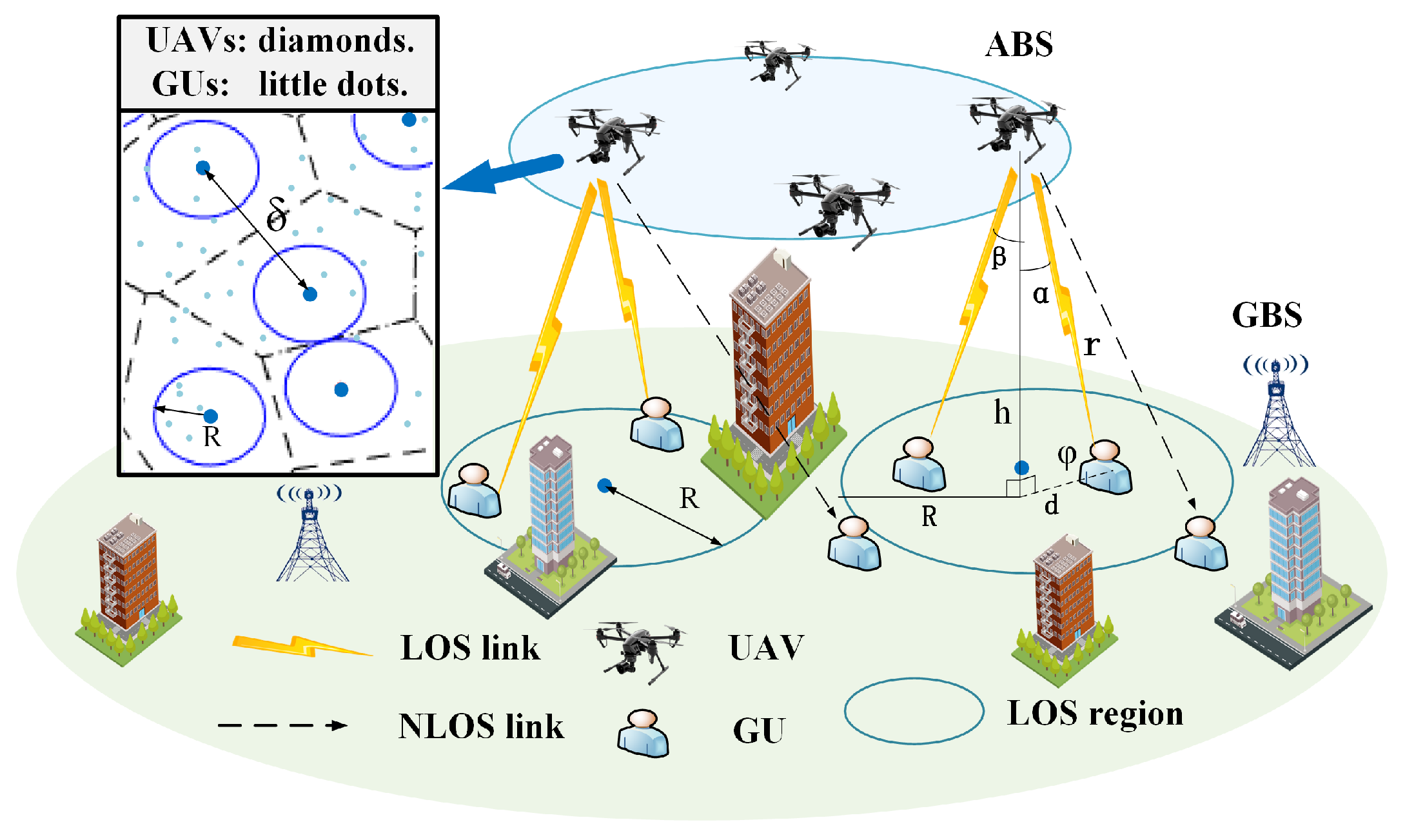
The rest of this article is organized as follows. Section 2 describes the system model. Section 3 provides the coverage probability and network capacity of mmWave UAV-aided network and derives an approximate expression for the coverage probability. Some numerical results are discussed in Section 4. Finally, Section 5 summarizes this article and looks forward to the application of the results.

2. System Model

As shown in Figure 1, we consider a mmWave UAV-aided network consisting of GBSs and rotary-wing UAVs as ABSs, GUs randomly distributed on the ground, and provided data services through LOS or NLOS channels by GBS or ABS. It is assumed that the UAVs hover at the same altitude with transmit power P t U . Due to the minimum distance constraint between UAVs, The locations of ABSs are modeled as an MHCPP Φ m with density λ u , as such, all ABSs have a guaranteed minimum distance δ between each other. The distribution of GUs and GBSs follow PPP Φ p with density λ p , and the UAVs are equipped with mmWave directional atennas to enhance the efficiency of network communication and isolate interference.
For the downlink of the G2G channel between GBS and GU, a standard large-scale path loss function ζ g ( r ) = T 1 r β is used, where T and β represent the additional path loss and path loss exponent for the G2G channel and r is the propagation distance.
Considering the characteristics of the A2G channel, we adopt a LOS/NLOS probability-based path loss model for UAV networks [35]:
ξ μ ( r ) = η μ r α μ / 2 = η μ d 2 + h 2 α μ / 2
where d is the horizontal distance between a typical GU and the target UAV, h represents the UAV altitude, and η μ and α μ ( μ { L , N } ) represent the additional path loss and path loss exponent for the LOS and NLOS channels, respectively. The probability that an A2G channel maintains LOS or NLOS connections is given by A L ( r ) = 1 / 1 + a e 180 π b θ + a b and A N ( r ) = 1 A L ( r ) [36], where a and b are the environment-related parameters and θ = arctan ( h / d ) is the elevation angle in degrees. For the proposed network, we can easily derive that the typical GU is located in the LOS region with a probability ε L = π R L 2 λ u , and in the NLOS region with a probability ε N = 1 ε L . To avoid strong LOS signal interference between neighboring UAVs, we set the guaranteed minimum distance δ 2 R L ; we further have ε N = ε N ( 1 ) + ε N ( 2 ) , where ε N ( 1 ) = λ u π δ 2 / 4 π R L 2 and ε N ( 2 ) = ε N ε N ( 1 ) .
In reality, the antennas of GBS usually tilt downwards to cover more GUs. Therefore, this paper uses multiple sector antennas to optimize the radiation range of GBS and assume that the antenna radiation direction of GBS is vertically oriented and horizontally omnidirectional.
To enhance network coverage performance and mitigate mutual interference, each UAV is equipped with a variable beamwidth conical antenna model to boost signal strength in specific directions. According to [22], the gain of a mmWave antenna array can be expressed as
G u ( φ ) = D o ( ω ) cos ( φ )
where D o ( ω ) represents the maximum directivity of the UAV antenna array, ω is the directivity parameter of the antenna array, cos ( φ ) represents the radiation efficiency of the antenna array, and φ [ 0 , π / 2 ] is the incident angle shown in Figure 1. The array gain G D A ( φ ) depends on the directivity parameter ω and radiation angle, and it is symmetric along the vertical direction. The maximum directivity of the UAV antenna array D o ( ω ) is
D o ( ω ) = 4 π Ω A ( ω )
where the beam solid angle of the antenna array Ω A ( ω ) is determined as
Ω A ( ω ) = 0 2 π 0 π U ω ( ρ ) sin ( ρ ) d ρ d τ = 0 2 π 0 π 2 cos ( ρ ) ω sin ( ρ ) d ρ d τ = π 2 ω
where U ω ( ρ ) = cos ( ρ ) / ω represents the normalized radiation intensity of the antenna array at ABS. Therefore, we can observe that a larger ω leads to a higher directivity of the antenna array, corresponding to a smaller half-power beamwidth. Consequently, it allows for the focusing of the radiated power within a smaller area. For the sake of simplicity, here we have ignored the influence of the effect on the antenna pattern and radio propagation caused by the airframe of the UAV [37].
Both the A2G and G2G channels are described by the Nakagami-m fading model to account for small-scale fading effects. Nakagami-m fading covers a wide range of fading scenarios in realistic wireless applications via parameter m, which includes the Rayleigh fading (m = 1) as a special case. Thus, the channel gain G c is a gamma random variable with a distribution of
f G ( g ) = g m ϑ 1 m ϑ m ϑ Γ m ϑ exp g m ϑ
where m ϑ , ϑ L , N , G represents the Nakagami-m fading parameter for the LOS A2G, NLOS A2G, and G2G channels, respectively. Therefore, the received power of a typical GU from the corresponding GBS and UAV can be expressed as
P r G = G c P t G ζ g ( r )
P r μ = G c P t μ ξ μ ( r ) D o ( ω ) cos ( φ )
where μ { L , N } represents the LOS or NLOS channel, r is the propagation distance between the UE and the server device, and P t μ ( μ { L , N } ) and P t G are the transmitting power for UAV and GBS, respectively.
Most research studies model the UAV positions as PPPs due to the ease of handling. In this paper, we model the UAVs as ABSs according to MHCPP distribution, which is denoted by Φ m with density λ u . For the PPP case, regarding a parent PPP Φ p , λ p is the density, so the probability that R > r simply equals the null probability of a PPP can be given by
F G ( r ) = 1 exp λ p π r 2
Accordingly, the probability density function (PDF) can be obtained as
f G ( r ) = d F G ( r ) d r = 2 π λ g r exp λ p π r 2
where the MHCPP type-II can be obtained by assigning a random mark uniformly distributed in [ 0 , 1 ] to each parent of Φ p [34]. Accordingly, the density of the UAV distributed of MHCPP can be derived as
λ u = 1 exp λ p π δ 2 π δ 2
where δ is a guaranteed minimum distance between ABSs, that is, the hard-core parameter in the MHCPP distribution.
However, for networks modeled using MHCPP, there is currently no known closed-form expression for the PDF of the nearest distance r between two nodes [38]. Due to the repulsion properties within MHCPP points, the calculation of interference is also very cumbersome. A simple approximate expression has been derived in [33]. Specifically, the distribution of MHCPP is approximated by the interference-to-signal ratio (ISR) distribution of PPP using the gain-based method based on ISR, given by
G m = M I S R p M I S R m
where MISR E ( ISR ) = E ( 1 / SIR ) represents the interference-to-signal ratio and G m represents the MISR gain when nodes are distributed by MHCPP.
Due to the ABSs being deployed according to MHCPP, if the distance between the typical GU and the server BS is r, there is no interfering BS that is closer to the typical GU [39]. The PDF of r is the underlying spatial distribution of the empty space in MHCPP. Using Campbell’s theorem, the PDF and cumulative distribution function (CDF) under an approximate distance-based MHCPP model can be approximated as [40]
f M ( r ) = f M 1 ( r ) = 2 π λ m r , 0 r δ / 2 f M 2 ( r ) = 2 π λ m r 2 r δ β 2 × exp 2 π λ m δ 2 β 4 π λ m δ 2 1 2 r δ β , r > δ / 2
F M ( r ) = F M 1 ( r ) = π λ m r 2 , 0 r δ / 2 F M 2 = 1 4 π λ m δ 2 4 × exp 2 π λ m δ 2 β 4 π λ m δ 2 1 2 r δ β , r > δ / 2
where r is the distance between the typical GU and the server BS, λ m represents the density of UAVs based on MHCPP, and β is a positive real parameter.

Interference Characteristics

For the cumulative interference, in this paper, we modeled them by the distance between two nodes. In other words, for a typical GUi, the interference of it can be represented as [41]:
I μ i = i Φ { o } P t μ G c ξ μ D B S G U
I G i = i Φ { o } P t G G c ζ μ D B S G U
where μ L , N represents the LOS and NLOS propagation through UAV, respectively. Φ R denotes the set of all transmitting nodes; o represents the typical GU; P t L , P t N , and P t G are the transmitting powers of UAV or GBS; and ξ μ ( r ) , ζ μ ( r ) represent the path loss function, assumed to depend only on the distance D B S _ G U from BS to typical GU. As UAV systems are usually interference-limited, we ignore the Gaussian noise.

3. Performance Analysis

In order to investigate the performance of mmWave UAV-aided networks, the coverage probability is obtained by using the Laplace transform of the interference, and the network achievable throughput and average ergodic rate are further derived in this section. Due to the characteristics such as the obstruction effect of mmWave, the path loss calculation methods are not the same in the three channel models, namely the G2G channel, A2G LOS channel, and A2G NLOS channel. Therefore, network performance under the above three channel conditions are comprehensively considered and carry out the weighted average so as to deduce the performance evaluation results of mmWave UAV-aided network more accurately.

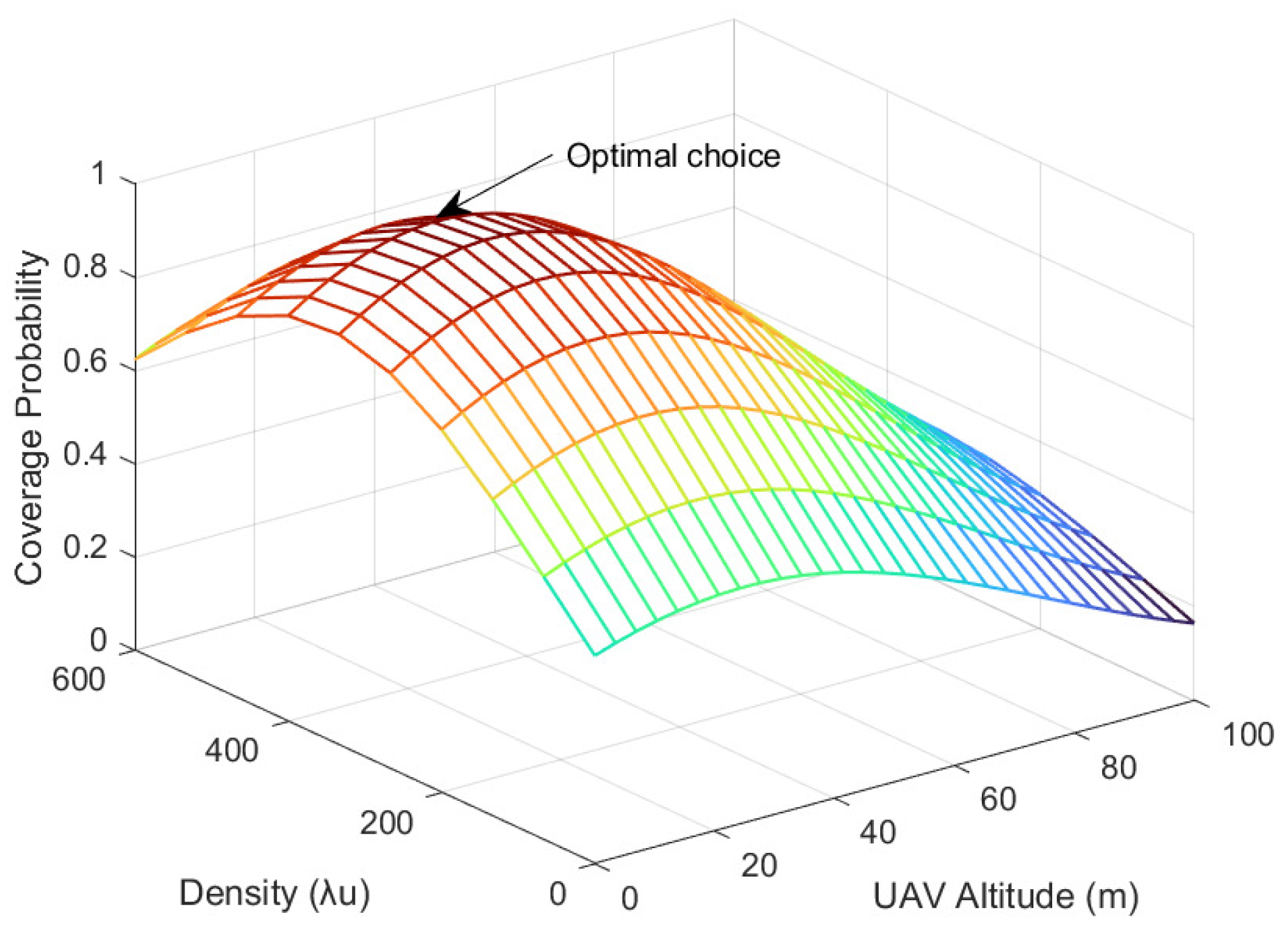
3.1. Coverage Probability

The coverage probability is calculated based on the distance between the ABS or GBS and the typical GU and the weighted sum of the association probability based on the received power of the GU under three channel conditions to comprehensively measure the total network coverage probability. Through this approach, the coverage probability P c o v is defined as the probability that a specific GU can achieve an SIR threshold Θ . In other words, the coverage probability of the network is the complementary cumulative distribution function (CCDF) of SIR. Considering the interference-limited network scenario, the CCDF of SIR is a crucial factor in analyzing network performance. Because the model in this paper represents a typical interference-limited network, we neglect the Gaussian noise. Therefore, the total coverage probability P c o v can be expressed as P S I R > Θ .
  • The SIR when a typical GU is associated with a UAV can be represented as:
    S I R μ i = G c D o ( ω ) cos ( φ ) P t μ ξ μ ( r ) I L i + I N i + I G i
    where μ { L , N } represents the LOS and NLOS channel, respectively, ξ μ ( r ) represents the distance-dependent path loss under different channel conditions, D o ( ω ) cos ( φ ) represents the directional antenna gain, and I g , I u , L and I u , N represent the interference from the GBS, LOS UAV, and NLOS UAV, respectively.
  • The SIR when the typical GU is associated with a GBS can be represented as:
    S I R G i = G c G g P t G ζ g ( r ) I L i + I N i + I G i
    where P t G is the transmit power of the GBS, G c represents the Rayleigh fading of the G2G channel, and G g is the antenna gain of the main lobe of GBS. We present I L i + I N i + I G i of I r for the total interference of our network in the following paper briefly.
Considering the properties of MHCPP, and to avoid strong LOS signal interference between neighboring UAVs, we set the minimum distance between ABSs as δ 2 R L , so R L = h tan θ represents the LOS coverage radius of each UAV on the ground.
Due to the sensitivity of mmWave networks to obstacles, when a typical GU selects the server BS, it is essential to consider not only the signal coverage range but also the size of received power at the typical GU after channel attenuation. Therefore, the coverage probability of a mmWave UAV-aided network can be represented as the weighted sum of the coverage probability under three channel conditions, taking into account both the signal coverage range and the typical GU’s received power, expressed as
P c o v = P σ · G σ , σ { A , G }
where P σ , σ { A , G } are the distance-based coverage probabilities and G σ , σ { A , G } are the power-based association probabilities on the condition that the serving node is ABS or GBS. The derivation process of their specific expression are provided in the following two sections.

3.1.1. Distance-Based Coverage Probability

In the A2G channel, the distribution for UAVs as ABSs in a mmWave UAV-aided network satisfies the MHCPP distribution. So, the system average coverage probability for the A2G channel from the nearest UAV to LOS and NLOS channel can be expressed as
P A = ε L P A L + ε N ( 1 ) P A ( N 1 ) + ε N ( 2 ) P A ( N 2 )
where P A L and P A N ( P A N { P A N 1 , P A N 2 } ) represent the coverage probabilities for the typical GU located in the LOS and NLOS regions expressed in (20), (22) and (23).
When r r L , the A2G channel corresponds to the LOS network, and the coverage probability can be derived as
P A L = 0 r L P [ S I R L > Θ r ] f M 1 ( r ) d r = 0 r L P [ S I R L > Θ r ] f M 1 ( r ) d r = ( a ) 0 r L exp Θ r α L / 2 P t L η L G u ( φ ) D o ( ω ) cos ( φ ) I r f M 1 ( r ) d r = ( b ) 0 r L L I L ( z 1 r ) L I N ( z 1 r ) L I G ( z 1 r ) f M 1 ( r ) d r
where z 1 = Θ r α L / 2 / P t L η L D o ( ω ) cos ( φ ) ; (a) follows the fact that G i exp ( 1 ) ; and (b) follows the independence of interference from GBS, LOS UAV, and NLOS UAV. The expressions of the Laplace transform L I L ( z 1 r ) , L I N ( z 1 r ) and L I G ( z 1 r ) are given in Equation (21) at the top of the next page, and the proof of them is in Appendix A Equation (A1).
When r L r δ / 2 , the A2G channel depends on the NLOS channel, so we can further obtain
L I L ( z r ) = exp 2 π λ u r t G L t 2 h 2 · 1 1 + z P t L D 0 ( ω ) h ω η L 1 m L t β L + ω m L d t L I N ( z r ) = exp 2 π λ u r t G N t 2 h 2 · 1 1 + z P t N D 0 ( ω ) h ω η N 1 m N t β N + ω m N d t L I G ( z r ) = exp 2 π λ m Δ r g _ r L z P t G G g T 1 t β 1 + z P t G G g T 1 t β t d t
P A ( N 1 ) = r L δ 2 P [ S I R N 1 > Θ r ] f M 1 ( r ) d r = r L δ 2 L I L z 2 r L I N z 2 r L I G z 2 r f M 1 ( r ) d r
where z 2 = Θ r α N / 2 / P t N η N D o ( ω ) cos ( φ ) .
In the case of r > δ / 2 , the A2G channel also depends on the NLOS channel, but the coverage region becomes irregular and is hard to be analyzed via conventional methods. In turn, we try to employ the method developed in [32] to solve the problem. We use the PDF of distance r derived from PPP model f G ( r ) to approximately calculate the second integral of Equation (19). Then, we have
P A ( N 2 ) = δ 2 P [ S I R N 2 > Θ r ] f M 2 ( r ) d r ( a ) δ 2 P r > δ 2 S I R N 2 > Θ * r f M 2 ( r ) d r ( b ) δ 2 P r > δ 2 G c G u ( φ ) P t N ξ N ( r ) σ I r > Θ * f M 2 ( r ) d r
= δ 2 exp σ Θ * r α N / 2 P t N η L D o ( ω ) cos ( φ ) I r f M 2 ( r ) d r = δ 2 L I L z 3 r L I N z 3 r L I G z 3 r f M 2 ( r ) d r
where z 3 = σ Θ * r α N / 2 / P t u η N D o ( ω ) cos ( φ ) , I r = I L + I N + I G represents the total network interference. Step (a) uses the substitution Equation (11) in Θ * = M I S R m = Θ / G m . Recent studies have shown that the network coverage probability based on non-PPP models can be approximately obtained by adjusting the SIR threshold of the corresponding networks via PPP models with the same density according to ASAPP [42]. Such a method is called ASAPPP, and the adjustment factor is named as the MSIR gain. So, we use this method to offset the SIR threshold. In step (b), we set σ = 1 dB according to the fact that the excess interference for the network modeled by MHCPP type-II compared with that by PPP never exceeds 1 dB [43].
Therefore, the probability of coverage through the LOS UAV can be further expressed as
P A L = ε L 0 r L P r R L S I R L > Θ f M 1 ( r ) d r
The probability of coverage through the NLOS UAV can be further expressed as
P A N = ε N ( 1 ) r L δ 2 P r L < r δ 2 S I R N 1 > Θ f M 1 ( r ) d r + ε N ( 2 ) δ 2 P r > δ 2 S I R N 2 > Θ f M 2 ( r ) d r δ 2 f M 2 ( r ) d r
We use f M 2 ( r ) , the PDF of distance r derived from the PPP model, to approximately calculate the second integral of Equation (25). Thus, we further utilize δ 2 f M 2 ( r ) d r to adjust the deviation brought by f M 2 ( r ) .
In the G2G channel, the coverage probability of a typical GU associated with GBS under the distribution of PPP can be expressed as
P G = 0 P G c > Θ T r β P t G G m I r · f G ( r ) d r = ( a ) 0 E I r exp Θ T r β P t G G m I r · f G ( r ) d r = 0 E I r exp Θ T r β P t G G m I L + I N + I G · f G ( r ) d r = ( b ) 0 L I L ( z r ) L I N ( z r ) L I G ( z r ) · f G ( r ) d r
where z = Θ T r β / P t G G m , P t G represents the transmitting power of GBS, T 1 r β represents the path loss function of the G2G channel, and f G ( r ) is the PDF of distance between the GU and the server BS that is based on the property of PPP. (a) follows the fact that G c exp ( 1 ) , and (b) follows the independence of interference from GBS, LOS UAV, and NLOS UAV.

3.1.2. Power-Based Association Probability

Based on the receiving power of the GU, the probability of the typical GU being connected to the NLOS UAV can be expressed as
G N = P ( E r N > E r L ; E r N > E r G ) = ( a ) P ( E r N > E r L ) × P ( E r N > E r G ) = P P t N D o ( ω ) cos ( φ ) η N r N α N > P t L D o ( ω ) cos ( φ ) η L r L α L · P P t N D o ( ω ) cos ( φ ) η N r N α N > P t G T r G β = ( b ) P ( r L > r N β N + m β + m ( η N η L ) 1 β L + m ) · P ( r g > r N α N + m β ( P t G η N P t N D o ( ω ) h m T ) 1 β ) = ( c ) h ( 1 F M 1 ( Δ r L r N ) f M 2 ( r ) d r · h ( 1 F G ( Δ r G r N ) f M 2 ( r ) d r
where P t N , P t L , P t G represent the received power from three channels, which are NLOS A2G, LOS A2G, and G2G; r N , r L , r G are the distance between the server BS and the GU under three channel conditions, respectively. (a) reflects the independent distribution of two point processes, and (b) is according to the fact that the channel gain is G u ( φ ) = D o ( ω ) cos ( φ ) when the incidence angle is φ and the antenna directional factor is ω . (c) is based on the definition of CDF and the average value on r N .
For simplicity, Δ r L r N Δ r G r N are used to represent the distance between the GU to the nearest LOS UAV (or GBS) except the server BS, while the distance between GU and its NLOS server BS is r (as expressed in the matrix on the top of the next page). Similarly, it can be concluded that the power-based probabilities for LOS UAV and GBS can be given by
G L = h 1 F M 2 Δ r N r L f M 1 ( r ) d r · h 1 F G Δ r L r N f M 1 ( r ) d r
G G = 0 1 F M 1 Δ r L r G f G ( r ) d r · h 1 F M 2 Δ r N r G f G ( r ) d r
Δ r N r N Δ r N r L Δ r N r G Δ r L r N Δ r L r L Δ r L r G Δ r G r N Δ r G r L Δ r G r G = r r α L + ω α N + ω η L η N 1 α N + ω r β α N + ω P t G D o ( ω ) h ω T P t N η N 1 α N + ω r α N + ω α L + ω η N η L 1 α L + ω r r β α L + ω P t G D o ( ω ) h ω T P t L η L 1 α L + ω r α N + m β P t G η N P t N D o ( ω ) h m T 1 β r α L + m β P t G η L P t L D o ( ω ) h m T 1 β r
To this extent, the total coverage probability of the system can be easily calculated following Equation (18).

3.2. Network Capacity

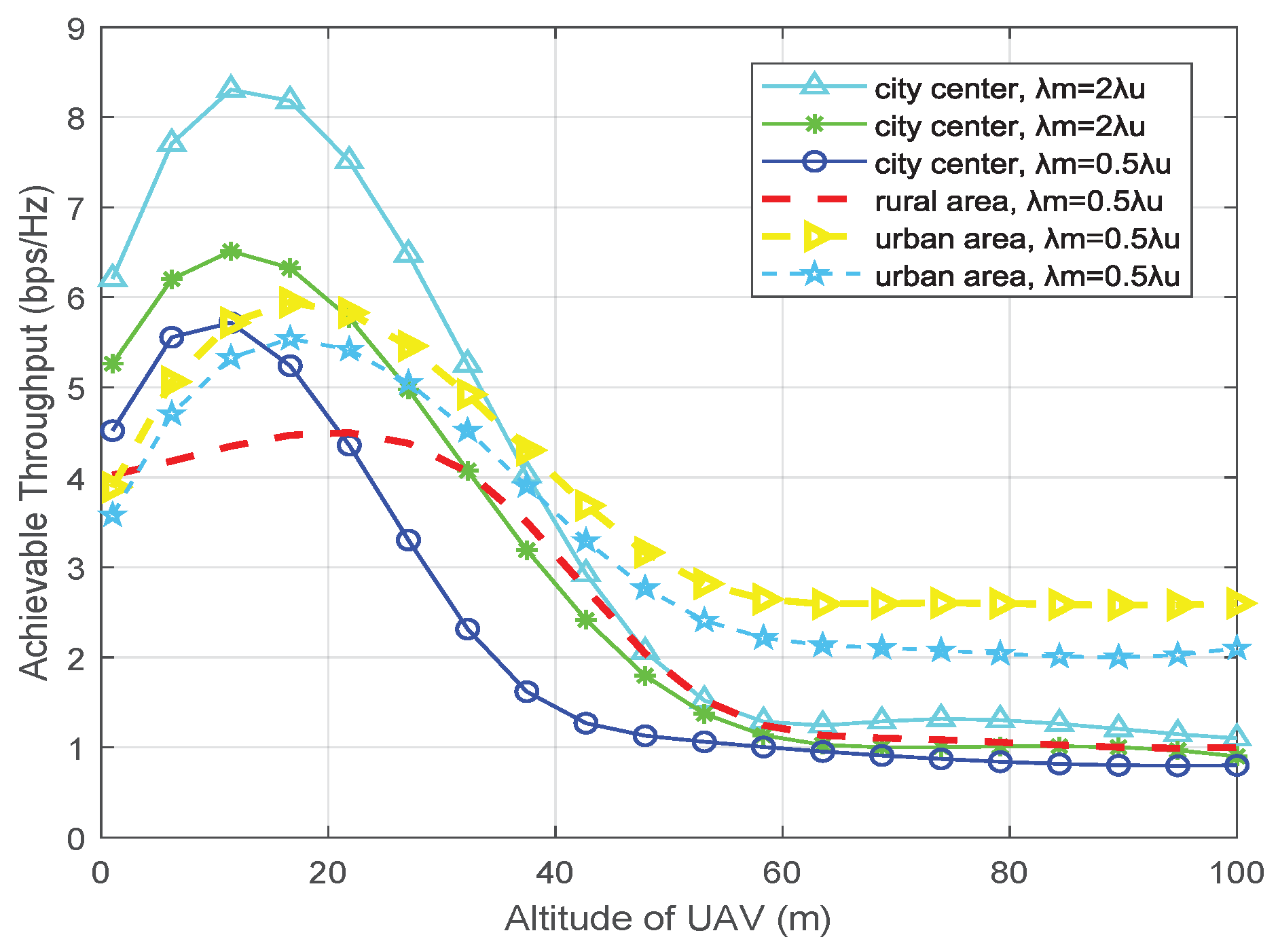
3.2.1. Achievable Throughput (ATH)

Considering an adaptive modulation and coding scheme, the network achievable throughput is the network channel capacity representing the highest bit rate that the typical GU could obtain, which can be derived from Shannon’s formula as
R E log 2 ( 1 + SIR ) ( b p s / Hz )
where the channel capacity R quantifies performance based on average throughput, while the coverage probability focuses on outcomes such as GU connection failures and other impacts related to service quality and link reliability. Therefore, R and P cov are complementary perspectives for evaluating the link quality between the server BS and the typical GU in the UAV-aided network.

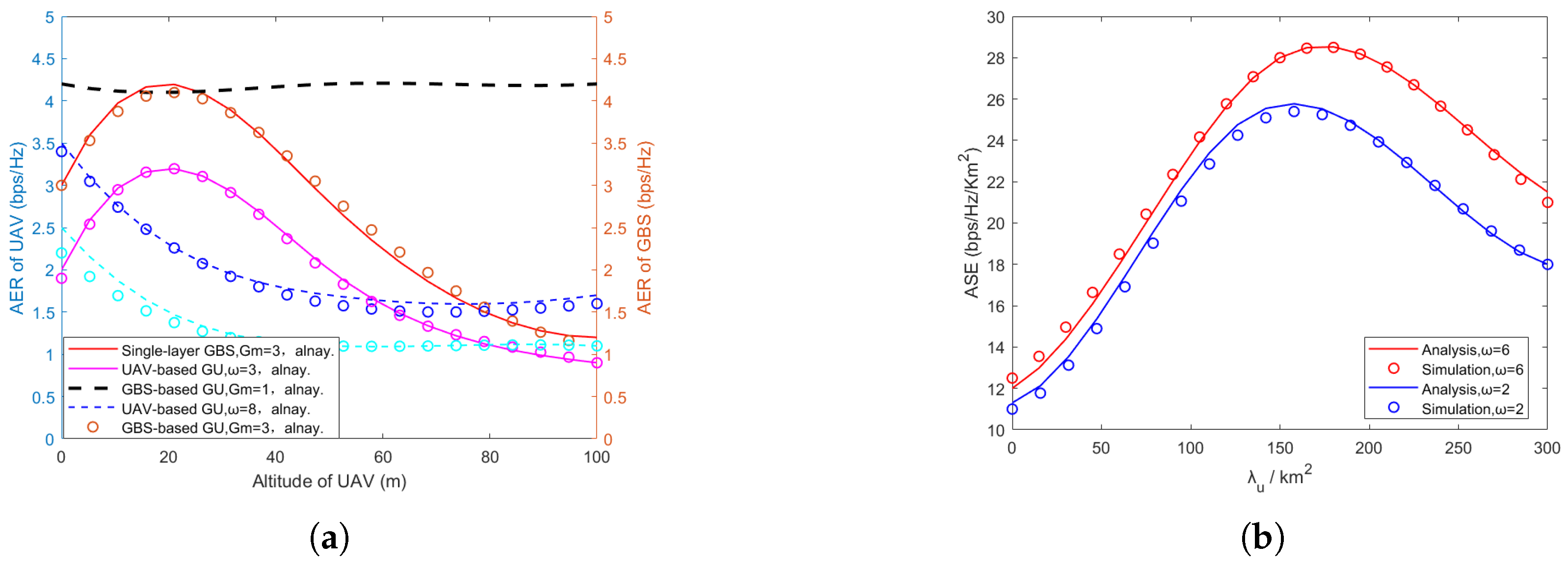
3.2.2. Average Ergodic Rate (AER)

Under the condition that the typical GU is associated with the server BS, the system AER can be expressed as [44]
R δ = E r E SIR δ log 2 1 + SIR δ ( b p s / Hz )
where δ { L , N , G } , r is the typical link between the GU and its server BS and E [·] is the average value of the received SIR distribution and the link length distribution. Thus, the specific expression of AER can be calculated.
Lemma 1.
The AER of a typical GU associated with the server GBS from the G2G channel is
R G = r G 0 q = 0 m g 1 ( t ) q q ! d q d z q L I G z 1 r · L I L z 1 r z 1 = Θ m L T r β P t G f G ( r ) d u d r
The AER of a typical GU associated with the server ABS from the A2G channel is given by
R A = R μ · G μ , μ { L , N }
where G μ ( μ { L , N } ) represents the association probability in the LOS and NLOS UAV channel based on the received power in Equations (27) and (28), respectively. R L , R N are derived as
R L = r L 0 q = 0 m L 1 ( t ) q q ! d q d z 2 q L I G z 2 r · L I L z 2 r z 2 = η Θ m L r β L 2 P t L f M 1 ( r ) d u d r
R N = r N 0 q = 0 m N 1 ( t ) q q ! d q d z 3 q L I G z 3 r · L I N z 3 r z 3 = η Θ m N r β N 2 P t N f M 1 ( r ) d u d r
the Laplace transform L I L z r , L I N z r and L I G z r are given by Equation (21); f M ( r ) ( M { M 1 , M 2 } ) are given by Equation (12).
Proof. 
Firstly, we consider the case where the typical mobile user is associated with the LOS UAV, and the AER can be derived as
R L = r L E SIR L log 2 1 + SIR L f M 1 ( r ) d r
where f M 1 ( r ) is given in Equation (12). Because E [ X ] = 0 P [ X > x ] d x for X > 0 , we further have
E L log 2 1 + SIR L = 0 P SIR L > Θ d u = ( a ) 0 E Φ m , Φ p G i > m L Θ r α s L P t L I L + I N d u = 0 E Φ m , Φ p exp I L + I N · l = 0 m L 1 m L Θ r α s L P t U q I L + I N q q ! d u = 0 q = 0 m L 1 ( t ) q q ! d q d z 2 q L I G z 2 r · L I L z 2 r z 2 = η Θ m L r α L 2 P t A f M 1 ( r ) d u
where the Laplace transforms are given by Equation (21) and d u is the integral calculus of SIR. Furthermore, we can derive the AER, which are represented as R N , R L , and R G , given by Equations (33), (35) and (36), respectively. □
Using the expressions of AER derived from the above three channels, we define R ergo = R N + R L + R G as the total AER of the typical GU, in which R N + R L represents the AER of the A2G channel and R G of the G2G channel, respectively.

3.2.3. Average Spectral Efficiency (ASE)

Average spectral efficiency (ASE) refers to the average amount of data or information that the system can transmit under a given spectrum resource. A higher average spectral efficiency means that the system can use the limited spectrum resources more effectively and achieve a higher data transmission rate. The key to calculating ASE is to calculate R L , R N , and R G to represent the AER. Let us denote λ m and λ g as the density of ABS and GBS; then, we can calculate the ASE using the following equation
A μ λ m ( R N + R L ) + λ p R G ( b p s / Hz / km 2 )
where R L , R N , and R G correspond to the AER of a typical GU associated with the server LOS UAV, NLOS UAV, or GBS.
Through analyzing the ASE, we aim to quantify the impact of adding ABSs to a mmWave network and investigate how the overall spectrum efficiency is affected when network resources are shared between ground and aerial BSs.

4. Simulation and Analysis

In this section, the numerical results along with Monte Carlo simulations are performed to verify the correctness of the theoretical analysis. We set the parameters of UAVs similar to [11,23], and the detailed parameter settings are in Table 2.

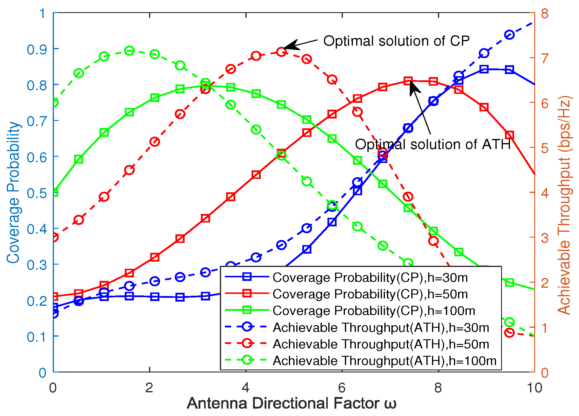
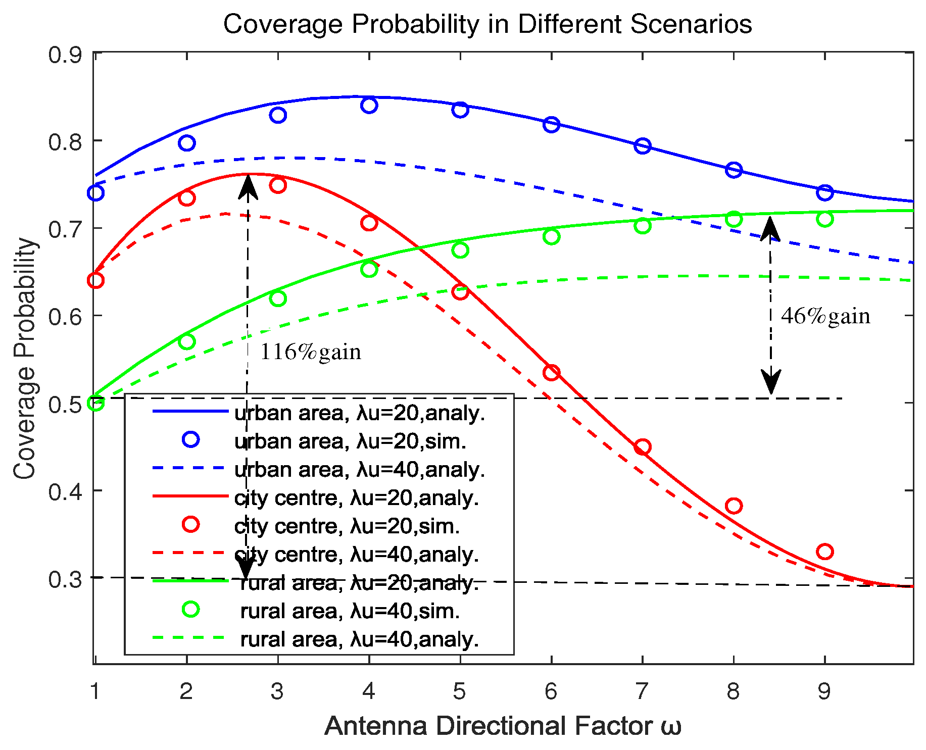
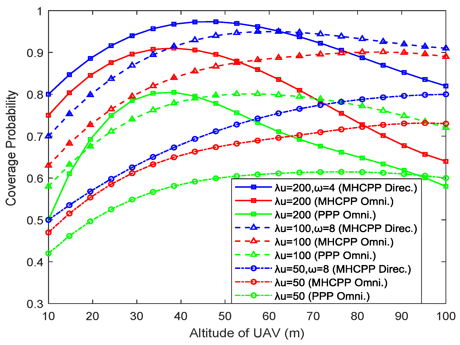
4.1. Coverage Probability

Figure 2 takes the impact of UAV density and antenna direction factor ω into consideration. Obviously, the network coverage probability is relatively highest in urban areas, and with the increase in ω , the trend of network changes in the city center scenario becomes more apparent; the experiments show that the simulation results when λ u = 40 are basically consistent with the trend of change at λ u = 20. This is because city centers always have many high-rise buildings, making the difference between the maximum and minimum coverage probability reach 116%. It can also be noticed that, in rural areas, with the higher altitude of UAVs promoting higher LOS communication links, a larger ω means a larger coverage probability, which can increase by almost 46%.
As shown in Figure 3, the coverage probability will reach its peak as ABS altitude h increases and then begin to decrease. This is because the probability of the A2G link maintaining the LOS connection increases, and an increase in distance will increase path loss and reduce signal power. Compared with traditional PPP distribution networks, the MHCPP distribution and mmWave antennas significantly isolate interference by maintaining the minimum safe distance δ and selecting the appropriate ω , resulting in a maximum increase of 28% in network coverage probability. In addition, the optimal beamwidth of mmWave antennas decrease with the increase in ABS density. In sparse network scenarios, a larger antenna directional factor ω should be given priority consideration. There are different optimal ABS altitudes under different ABS densities. In future research, we will focus on solving the optimization problem of network performance under constraints such as the beamwidth, altitude, and density of ABSs.
Figure 4 shows the joint impact of UAV altitude h and density λ u on the coverage probability of mmWave UAV-aided networks. It is not difficult to see that the coverage probability of the typical GU first increases until reaching the upper limit of about 89 % and then decreases to about 37 % . Considering limited frequency resources or the complexity and cost of antenna design, when using the same frequency and antenna configuration at BSs, due to the obstacle effect of mmWave communications, it will lead to higher UAV density and greater co-frequency interference. At this time, the decrease in UAV density can reduce co-frequency interference to some extent, indicating that we can further study how to balance the distance and quantity between ABS and GBS and optimize algorithms to achieve optimal network performance.

4.2. Network Capacity

Figure 5a shows the average data rate for UAV users and GBS users in UAV-aided network, as well as the AER in the single-layer GBS network. It can be observed that the deployment of UAVs introduces cross-layer interference and degrades the performance of GBS users. Increasing the altitude of UAVs can mitigate interference and increase connectivity, thereby improving AER of UAVs by 47% when ω = 3. Simulation results are consistent with theoretical results, represented by circular lines in the same figure.
Figure 5b illustrates the relationship between the system ASE and UAV density. It is evident that deploying UAVs to assist GBS can effectively enhance the overall ASE of the system. However, when the UAV density becomes too high, the interference also increases. At this point, the negative impact of inter-cell interference outweighs the benefits of dense deployment, resulting in a decline in system ASE by 27% when ω = 6 . Based on these results, the UAV altitude and beamwidth in a UAV-aided network can be established as an optimization problem: the goal is to maintain a certain AER for GBS users while adjusting the UAV beamwidth and deployment height to achieve the optimal configuration of UAV parameters. This approach maximizes AER while ensuring a balanced overall system performance.
Figure 6 illustrates the impact of BS densities on network achievable throughput at different UAV altitudes. Due to the large number of high-rise buildings in city centers, the corresponding obstruction effect is significant and the coverage of GBS signals is significantly limited. When the density of UAVs is half of that of GBSs, the network achievable throughput increases to 86%. The building density in urban areas is relatively low compared with urban centers, and the impact of UAVs on throughput is not significant, indicating that the deployment of GBS basically meets the communication needs of ordinary urban areas. These results are consistent with the findings reported in [11]. In rural areas, where GBS density is low, the deployment of UAVs can be an effective means of improving network capacity. Overall, the dense distribution of UAVs can provide better network coverage and capacity support for densely populated urban areas and sparsely populated rural areas, while the deployment of GBSs plays a greater role in urban areas. In addition, due to the game between the interference isolation and expanding coverage of mmWave antennas, there is an optimal flight altitude of UAVs that maximizes the network performance.

4.3. Overall Performance

Figure 7 demonstrates that appropriately selecting the width of the UAV can significantly improve network performance. A larger UAV beamwidth reduces the possibility of having no BS within main lobe, thereby increasing both coverage probability and throughput. However, increasing the beamwidth also leads to an increase in the number of interfering BSs, resulting in performance degradation. It is observed that increasing beamwidth actually decreases the antenna gain and received signal power. A similar effect occurs on the received interference power from each interfering BS. Because the impact of desired signal and interference is proportional, the SIR remains approximately unchanged in interference-limited scenarios. It can be noticed that the optimal beamwidth for maximizing does not necessarily maximize throughput as throughput is the average value over the entire SIR distribution while coverage probability only depends on a specific SIR threshold. Therefore, an optimization design needs to find a compromise between these conflicting objectives and establish a trade-off between throughput and coverage. The results highlight the importance of selecting an appropriate beamwidth for UAV antennas to achieve optimal network performance.

5. Conclusions

In this article, by considering the repulsive relationship between UAVs, we optimized the deployment of ABSs based on MHCPP distribution and further reduced mutual interference between BSs using a mmWave antenna model with variable beam width and direction and analyzed the coverage probability and network capacity of a mmWave UAV-aided network. In addition, we proposed a method for selecting server BSs in UAV-aided networks based on distance and received power and provided an approximate expression for calculating network coverage probability. Numerical analysis and simulation results indicated that with the enhancement of antenna directionality, the coverage probability in rural areas could increase by 46%. In the city center, when the density of UAVs was half of the density of GBSs, the network throughput could reach 86%. The theoretical results are consistent with the simulation results. Future work will focus on optimizing the performance of mmWave UAV-aided networks.

Author Contributions

Conceptualization, X.W., R.X., L.P. and A.L.; methodology, X.W. and R.X.; software, X.W. and X.Y.; validation, X.W., L.P. and A.L.; writing—original draft preparation, X.W.; writing—review and editing, X.W., L.P. and A.L.; supervision, R.X. and L.P.; funding acquisition, L.P. and H.W. All authors have read and agreed to the published version of the manuscript.

Funding

This work is supported by the National Natural Science Foundation of China (No. 61671471, No. 62171465).

Data Availability Statement

The data used to support the findings of this study are available from the corresponding author upon request.

Conflicts of Interest

The authors declare no conflicts of interest.

Abbreviations

The following abbreviations are used in this manuscript:
BSBase station
GUGround user
UAVsUnmanned aerial vehicles
mmWaveMillimeter wave
MHCPPMatérn hard-core point process
IoTInternet of Things
PPPPoisson point process
GPPBinomial point processes
β -GPP β -Ginibre point process
LOSLine-of-sight
NLOSNon-line-of-sight
GBSsGround base stations
ABSsAir base stations
SBSServe base station
SIRSignal-to-interference ratio
MISRMean of interference-to-signal ratio
CCDFComplementary cumulative distribution function

Appendix A. Proof of Laplace Transform of I L, I N, I G

In the A2G channel, the Laplace transform of the interference from UAVs in the NLOS channels is derived as
L I N ( z r ) = E exp z j r j > Δ r N r x G j P t N D o ( ω ) h r ω η N r j α N = E j r j > Δ r N r x E G j exp z G j P t N D o ( ω ) h ω η N r j α N + ω = ( a ) E j r j > Δ r N r x 1 + z P t N D o ( ω ) h ω η N r j α N + ω m N m N = ( b ) exp 2 π λ u Δ r N r x t G N t 2 h 2 · 1 1 + z P t N D o ( ω ) h ω η N t α N + ω m N m N d t
where (a) is derived from the moment-generating function (MGF) of the gamma random variable G i . (b) is generated from the probability generating function (PGFL) E x Ψ f ( x ) = exp λ R 2 ( 1 f ( x ) ) d x of PPP. Next, we use the same mathematical derivation method and then conclude that the Laplace transform of the interference from LOS UAVs L I L ( z r ) and GBSs L I G ( z r ) are
L I L ( z r ) = exp 2 π λ u r t G L t 2 h 2 · 1 1 + z P t L D o ( ω ) h ω η L 1 t β L + ω m L m L d t
L I G ( z r ) = exp 2 π λ m Δ r G r L z P t G G g T 1 t β 1 + z P t G G g T 1 t β t d t

References

  1. Liu, Y.; Xiong, K.; Ni, Q.; Fan, P.; Letaief, K.B. UAV-assisted wireless powered cooperative mobile edge computing: Joint offloading, CPU control, and trajectory optimization. IEEE Internet Things J. 2019, 7, 2777–2790. [Google Scholar] [CrossRef]
  2. Chen, Z.; Zhang, H. UAV-assisted networks through a tunable dependent model. IEEE Commun. Lett. 2020, 24, 1110–1114. [Google Scholar] [CrossRef]
  3. Chen, Y.; Zhang, H. UAV networks through a spatial repulsion model. IEEE Wirel. Commun. Lett. 2021, 11, 101–105. [Google Scholar] [CrossRef]
  4. Wang, C.; Deng, D.; Xu, L.; Wang, W. Resource scheduling based on deep reinforcement learning in UAV assisted emergency communication networks. IEEE Trans. Commun. 2022, 70, 3834–3848. [Google Scholar] [CrossRef]
  5. Illian, J.; Penttinen, A.; Stoyan, H.; Stoyan, D. Statistical Analysis and Modelling of Spatial Point Patterns; John Wiley & Sons: Hoboken, NJ, USA, 2008. [Google Scholar]
  6. Stoyan, D.; Stoyan, H. On one of Matérn’s hard-core point process models. Math. Nachrichten 1985, 122, 205–214. [Google Scholar] [CrossRef]
  7. Li, J.; Niu, Y.; Wu, H.; Ai, B.; Chen, S.; Feng, Z.; Zhong, Z.; Wang, N. Mobility support for millimeter wave communications: Opportunities and challenges. IEEE Commun. Surv. Tutorials 2022, 24, 1816–1842. [Google Scholar] [CrossRef]
  8. Wang, Z.; Hall, P.S.; Kelly, J.R.; Gardner, P. Wideband frequency-domain and space-domain pattern reconfigurable circular antenna array. IEEE Trans. Antennas Propag. 2017, 65, 5179–5189. [Google Scholar] [CrossRef]
  9. Lu, X.; Salehi, M.; Haenggi, M.; Hossain, E.; Jiang, H. Stochastic geometry analysis of spatial-temporal performance in wireless networks: A tutorial. IEEE Commun. Surv. Tutorials 2021, 23, 2753–2801. [Google Scholar] [CrossRef]
  10. Ghamari, M.; Rangel, P.; Mehrubeoglu, M.; Tewolde, G.; Sherratt, R.S. Unmanned aerial vehicle communications for civil applications: A review. IEEE Access 2022, 10, 102492–102531. [Google Scholar] [CrossRef]
  11. Azari, M.M.; Rosas, F.; Pollin, S. Cellular connectivity for UAVs: Network modeling, performance analysis, and design guidelines. IEEE Trans. Wirel. Commun. 2019, 18, 3366–3381. [Google Scholar] [CrossRef]
  12. Al-Hourani, A.; Evans, R.J.; Kandeepan, S. Nearest neighbor distance distribution in hard-core point processes. IEEE Commun. Lett. 2016, 20, 1872–1875. [Google Scholar] [CrossRef]
  13. Zhang, S.; Zhu, Y.; Liu, J. Multi-UAV Enabled Aerial-Ground Integrated Networks: A Stochastic Geometry Analysis. IEEE Trans. Commun. 2022, 70, 7040–7054. [Google Scholar] [CrossRef]
  14. Peng, J.; Tang, W.; Zhang, H. Directional Antennas Modeling and Coverage Analysis of UAV-Assisted Networks. IEEE Wirel. Commun. Lett. 2022, 11, 2175–2179. [Google Scholar] [CrossRef]
  15. Wu, H.; Tao, X.; Zhang, N.; Shen, X. Cooperative UAV cluster-assisted terrestrial cellular networks for ubiquitous coverage. IEEE J. Sel. Areas Commun. 2018, 36, 2045–2058. [Google Scholar] [CrossRef]
  16. Wei, X.; Peng, L.; Xu, R.; Li, A.; Yu, X.; Xu, Z. Performance Optimization of UAV-Assisted Networks with mmWave Antennas. In Proceedings of the 2023 International Conference on Wireless Communications and Signal Processing (WCSP), Hangzhou, China, 2–4 November 2023; pp. 652–657. [Google Scholar]
  17. Ge, Y.; Zhang, W.; Gao, F.; Zhang, S.; Ma, X. Beamforming network optimization for reducing channel time variation in high-mobility massive MIMO. IEEE Trans. Commun. 2019, 67, 6781–6795. [Google Scholar] [CrossRef]
  18. Gupta, L.; Jain, R.; Vaszkun, G. Survey of important issues in UAV communication networks. IEEE Commun. Surv. Tutorials 2015, 18, 1123–1152. [Google Scholar] [CrossRef]
  19. Debogovic, T.; Perruisseau-Carrier, J.; Bartolic, J. Partially reflective surface antenna with dynamic beamwidth control. IEEE Antennas Wirel. Propag. Lett. 2010, 9, 1157–1160. [Google Scholar] [CrossRef]
  20. Guo, X.; Zhang, C.; Yu, F.; Chen, H. Coverage analysis for UAV-assisted mmwave cellular networks using poisson hole process. IEEE Trans. Veh. Technol. 2021, 71, 3171–3186. [Google Scholar] [CrossRef]
  21. Susarla, P.; Gouda, B.; Deng, Y.; Juntti, M.; Silvén, O.; Tölli, A. Learning-Based Beam Alignment for Uplink mmWave UAVs. IEEE Trans. Wirel. Commun. 2022, 22, 1779–1793. [Google Scholar] [CrossRef]
  22. Yang, B.; Taleb, T.; Shen, Y.; Jiang, X.; Yang, W. Performance, fairness, and tradeoff in UAV swarm underlaid mmWave cellular networks with directional antennas. IEEE Trans. Wirel. Commun. 2020, 20, 2383–2397. [Google Scholar] [CrossRef]
  23. Sun, H.; Ma, C.; Zhang, L.; Li, J.; Wang, X.; Li, S.; Quek, T.Q. Coverage analysis for cellular-connected random 3D mobile UAVs with directional antennas. IEEE Wirel. Commun. Lett. 2023, 12, 550–554. [Google Scholar] [CrossRef]
  24. Chang, H.; Wang, C.X.; Liu, Y.; Huang, J.; Sun, J.; Zhang, W.; Gao, X. A novel nonstationary 6G UAV-to-ground wireless channel model with 3-D arbitrary trajectory changes. IEEE Internet Things J. 2020, 8, 9865–9877. [Google Scholar] [CrossRef]
  25. Wei, Z.; Zhu, J.; Guo, Z.; Ning, F. The performance analysis of spectrum sharing between UAV enabled wireless mesh networks and ground networks. IEEE Sens. J. 2020, 21, 7034–7045. [Google Scholar] [CrossRef]
  26. Wang, X.; Zhang, H.; Tian, Y.; Leung, V.C. Modeling and analysis of aerial base station-assisted cellular networks in finite areas under LoS and NLoS propagation. IEEE Trans. Wirel. Commun. 2018, 17, 6985–7000. [Google Scholar] [CrossRef]
  27. Qin, S.; Peng, L.; Xu, R.; Wei, X.; Wei, X.; Jiang, D. Performance Analysis of Multi-Hop Flying Mesh Network Using Directional Antenna Based on β-GPP. Drones 2023, 7, 335. [Google Scholar] [CrossRef]
  28. Matracia, M.; Kishk, M.A.; Alouini, M.S. Coverage analysis for UAV-assisted cellular networks in rural areas. IEEE Open J. Veh. Technol. 2021, 2, 194–206. [Google Scholar] [CrossRef]
  29. Wang, Y.; Su, Z.; Xu, Q.; Li, R.; Luan, T.H.; Wang, P. A secure and intelligent data sharing scheme for UAV-assisted disaster rescue. IEEE/ACM Trans. Netw. 2023, 31, 2422–2438. [Google Scholar] [CrossRef]
  30. Ren, H.; Pan, C.; Wang, K.; Deng, Y.; Elkashlan, M.; Nallanathan, A. Achievable data rate for URLLC-enabled UAV systems with 3-D channel model. IEEE Wirel. Commun. Lett. 2019, 8, 1587–1590. [Google Scholar] [CrossRef]
  31. Zhang, C.; Zhang, W.; Wang, W.; Yang, L.; Zhang, W. Research challenges and opportunities of UAV millimeter-wave communications. IEEE Wirel. Commun. 2019, 26, 58–62. [Google Scholar] [CrossRef]
  32. Yang, J.; Pan, Z.; Guo, L. Coverage and energy efficiency analysis for two-tier heterogeneous cellular networks based on matérn hard-core process. Future Internet 2019, 12, 1. [Google Scholar] [CrossRef]
  33. Haenggi, M. The mean interference-to-signal ratio and its key role in cellular and amorphous networks. IEEE Wirel. Commun. Lett. 2014, 3, 597–600. [Google Scholar] [CrossRef]
  34. Chen, Y.; Zhang, H.; Xu, M. The coverage problem in UAV network: A survey. In Proceedings of the Fifth International Conference on Computing, Communications and Networking Technologies (ICCCNT), Hefei, China, 11–13 July 2014; pp. 1–5. [Google Scholar]
  35. Al-Hourani, A.; Kandeepan, S.; Jamalipour, A. Modeling air-to-ground path loss for low altitude platforms in urban environments. In Proceedings of the 2014 IEEE Global Communications Conference, Austin, TX, USA, 8–12 December 2014; pp. 2898–2904. [Google Scholar]
  36. Al-Hourani, A.; Kandeepan, S.; Lardner, S. Optimal LAP altitude for maximum coverage. IEEE Wirel. Commun. Lett. 2014, 3, 569–572. [Google Scholar] [CrossRef]
  37. Mao, K.; Zhu, Q.; Qiu, Y.; Liu, X.; Song, M.; Fan, W.; Kokkeler, A.B.; Miao, Y. A uav-aided real-time channel sounder for highly dynamic non-stationary A2G scenarios. IEEE Trans. Instrum. Meas. 2023, 72, 6504515. [Google Scholar] [CrossRef]
  38. Zhu, Y.; Zhang, S. Modeling and Analysis of Multi-UAV Networks Using Matérn Hard-Core Point Process. In Proceedings of the 2022 IEEE 23rd International Conference on High Performance Switching and Routing (HPSR), Taicang, China, 6–8 June 2022; pp. 89–94. [Google Scholar]
  39. Chen, Y.; Yang, J.; Cao, X.; Zhang, S. Energy efficiency optimization for heterogeneous cellular networks modeled by Matérn hard-core point process. China Commun. 2020, 17, 70–80. [Google Scholar] [CrossRef]
  40. Chen, C.; Elliott, R.C.; Krzymień, W.A. Empirical distribution of nearest-transmitter distance in wireless networks modeled by Matérn hard core point processes. IEEE Trans. Veh. Technol. 2017, 67, 1740–1749. [Google Scholar] [CrossRef]
  41. Haenggi, M.; Ganti, R.K. Interference in large wireless networks. Found. Trends® Netw. 2009, 3, 127–248. [Google Scholar] [CrossRef]
  42. ElSawy, H.; Hossain, E.; Haenggi, M. Stochastic geometry for modeling, analysis, and design of multi-tier and cognitive cellular wireless networks: A survey. IEEE Commun. Surv. Tutorials 2013, 15, 996–1019. [Google Scholar] [CrossRef]
  43. Haenggi, M. Mean interference in hard-core wireless networks. IEEE Commun. Lett. 2011, 15, 792–794. [Google Scholar] [CrossRef]
  44. Sun, H.; Wang, X.; Zhang, Y.; Quek, T.Q. Performance analysis and cell association design for drone-assisted heterogeneous networks. IEEE Trans. Veh. Technol. 2020, 69, 13741–13755. [Google Scholar] [CrossRef]
Figure 1. System model of the mmWave UAV-aided network.
Drones 08 00152 g001
Figure 2. Relationship between coverage probability and ω under different scenarios. The environment parameters (a, b) are set to be (5.3, 0.45), (10.12, 0.16), and (23.2, 0.07) for the rural area, urban area, and city center, respectively.
Drones 08 00152 g002
Figure 3. Relationship between coverage probabilities and UAV altitude under different UAV density λ u while d = 50 m.
Drones 08 00152 g003
Figure 4. Coverage probabilities of the typical GU as a joint function of density and altitude, with ω = 5 and d = 60 m.
Drones 08 00152 g004
Figure 5. The variation of system AER and ASE with the UAV beamwidth and deployment height. (a) AER of GUs served from ABSs and GBSs. (b) System ASE of UAV-aided network.
Drones 08 00152 g005
Figure 6. Network capacity of the typical GU at different UAV altitudes.
Drones 08 00152 g006
Figure 7. The relationship between network coverage probability, achievable throughput, and antenna directional factor ω under different UAV altitudes.
Drones 08 00152 g007
Table 1. Comparison of existing surveys.
ReferenceYearNode DistributionSmall-Scale Fading ModelAntenna ModelPower-Based Association ProbabilityPerformance Metrics
[26]2018HPPPNakagami-m--CP/ASE
[32]2019MHCPPRayleigh--CP/Energy efficiency
[33]2020MHCPPRayleigh--CP/ATH/Energy efficiency
[28]2021PPPNakagami-m-CP/Association probability
[13]2022MHCPPNakagami-m--CP/Average rate
[20]2022Poisson hole processNakagami-mmmWave antenna-CP/Distance-based association probability
[34]2022MHCPPRayleigh--CP/Average rate
[23]2023HPPPNakagami-mConical antenna-CP/Handover probability
[27]2023 β -GPP-Conical antenna-CP/Ergodic capacity
Our Paper2024MHCPPNakagami-mmmWave antennaCP/ATH/ASE/AER
Table 2. Simulation parameters.
ParameterDescriptionValue
P t μ , P t G Transmission power of BSs(23, 40) dBm
hFlight altitude of ABSs(30, 40, 50, 100) m
λ p , λ m Density of BSs(20, 200)/km2
m, m μ Paramenters of Nakagami-m fading model(1, 1.5)
α L , α N , β Path loss exponent(2.5, 3.5, 2.5)
η L , η N ,TAdditional path loss(1, 10, 1) dB
a,bEnvironmental-related parameters(10.12, 0.16)
Disclaimer/Publisher’s Note: The statements, opinions and data contained in all publications are solely those of the individual author(s) and contributor(s) and not of MDPI and/or the editor(s). MDPI and/or the editor(s) disclaim responsibility for any injury to people or property resulting from any ideas, methods, instructions or products referred to in the content.

