

Automatic Road Pavement Distress Recognition Using Deep Learning Networks from Unmanned Aerial Imagery
 ,
, 
Abstract
:1. Introduction
Pavement Distresses
- Pavement Crack Group: The crack group in this article includes transverse, longitudinal, oblique, and alligator cracks (Figure 1a). Causes of this type of distress include climatic changes (the most important cause), weak line connections, thermal expansion and contraction of the surface, and surface deviations on an unstable substrate. Alligator cracking, on the other hand, is related to asphalt concrete surface fatigue from repeated traffic loading, a weak or thin base or surface, or inadequate drainage [10].
- Repaired Segment: Repaired segments are portions of a pavement surface that are removed and replaced after construction of the original surface or on which additional material is placed (Figure 1b). To repair distresses in the road surface or to cover a utility trench, patches are generally used. This distress is caused by inadequate compaction of the patch and improper infrastructure [10].
- Delamination: This is a type of distress that occurs in different pavement layers. In this case, the asphalt layers wear away and the lower layer appears (Figure 2a). Several things can lead to this type of distress, such as the breaking of the bonds between the layers due to water seeping through the asphalt, the presence of a weak layer under the wearing surface, and an inadequate tack coat before the placement of the upper layers [43].
- Pothole: These are bowl-shaped holes in the road surface that can occur for various reasons (Figure 2b). The reasons for the formation of potholes include damage to the subgrade, base course, or pavement bed, poor drainage, movement of small pavement pieces that are not held firmly in place, and defects in the construction of the asphalt mix [10].
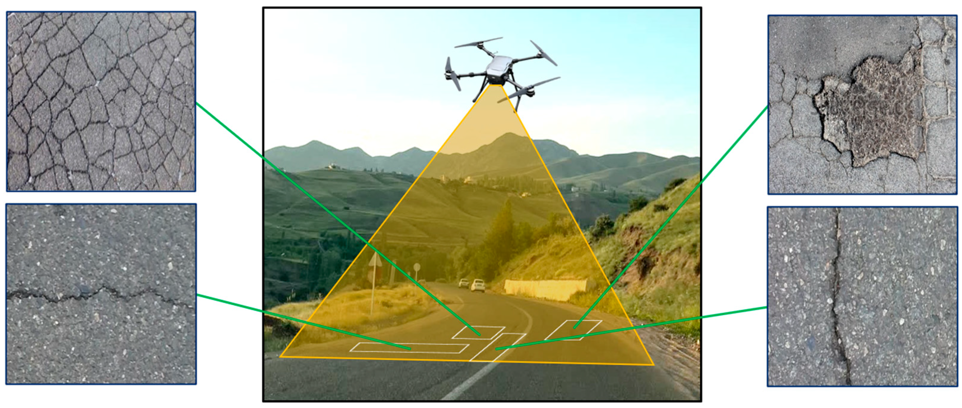
- Distresses: These have been investigated as transverse cracks, longitudinal cracks, alligator cracks, oblique cracks, potholes, repairs, and delamination.
2. Related Works
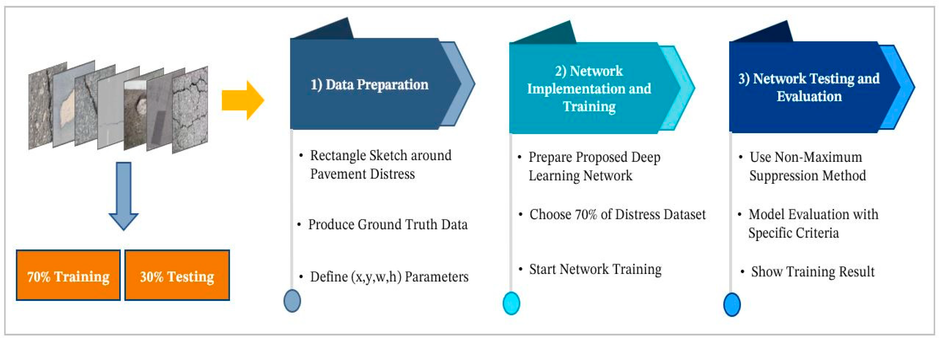
3. Methodology
3.1. Data Preparation
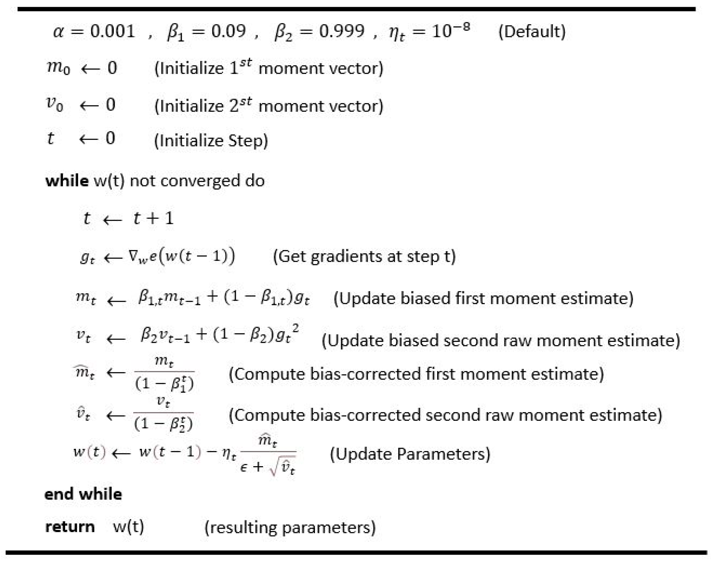
3.2. The Implementation and Training of the Network
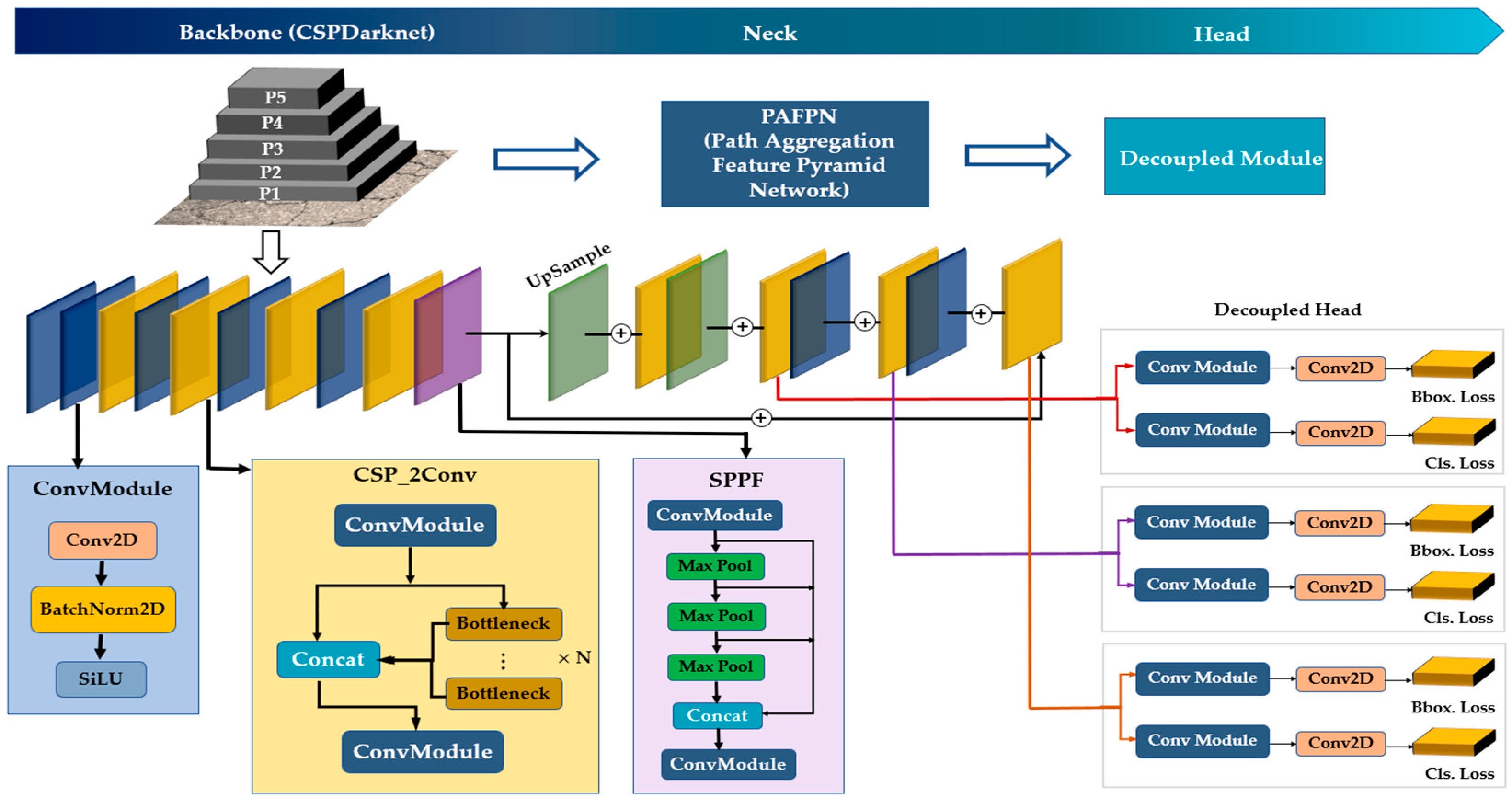
The Network Architecture
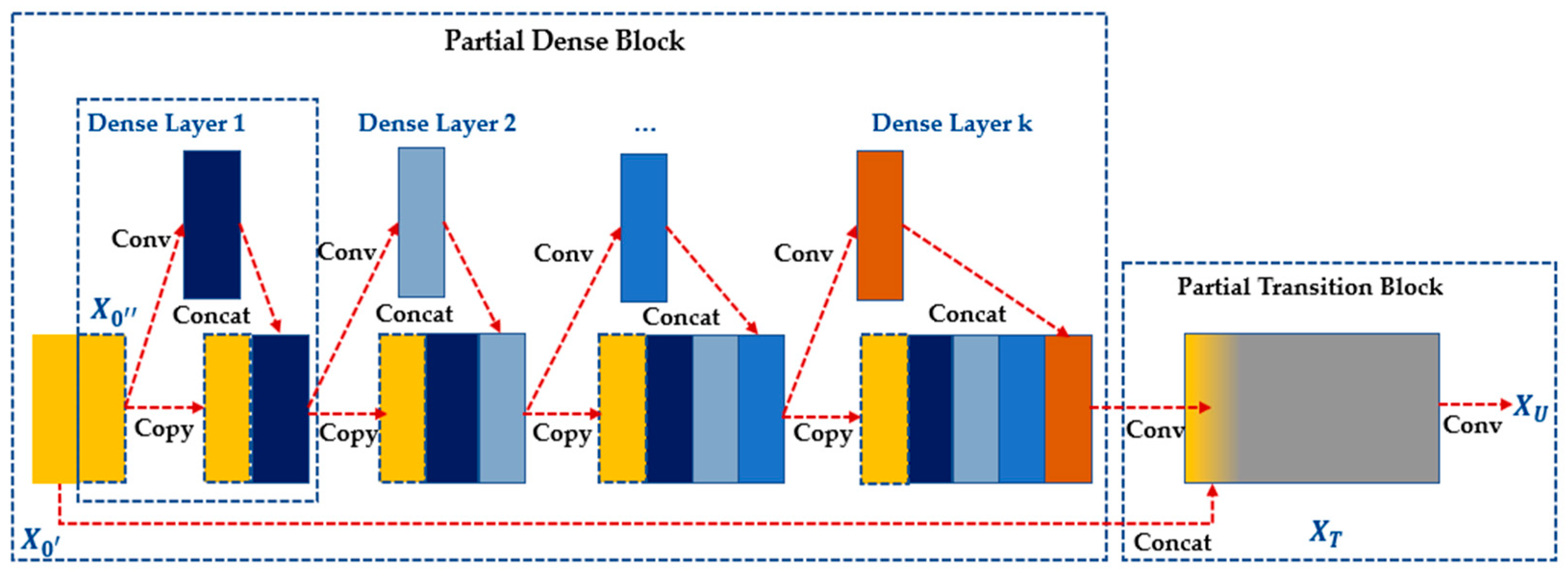
- Backbone
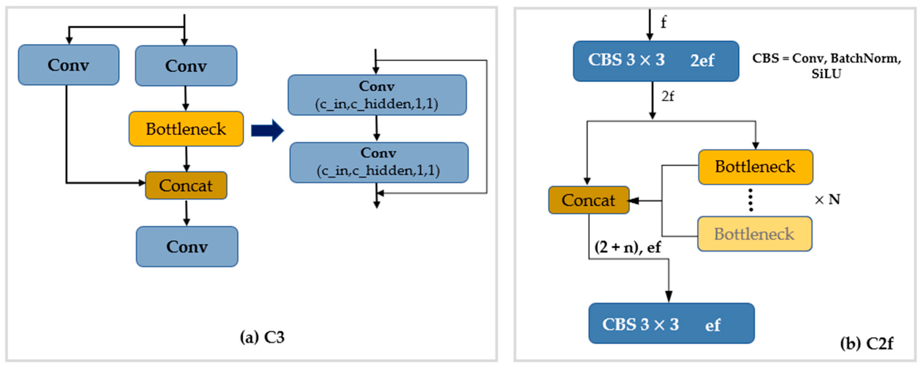
- Bottleneck CSP Module
- C2F Module
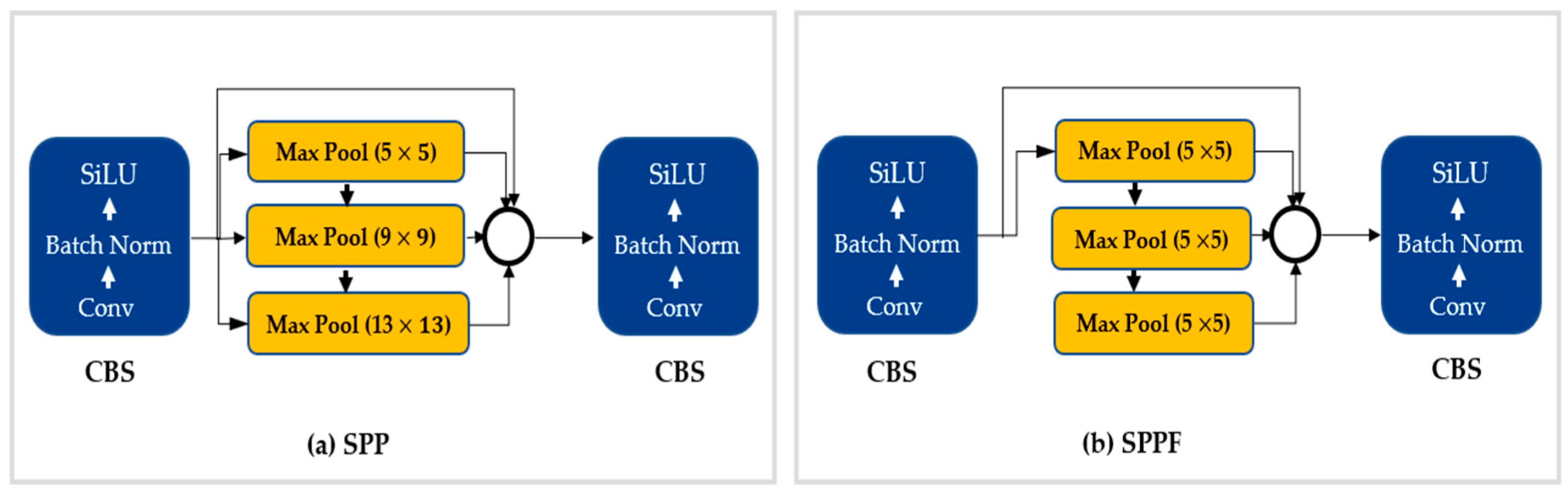
- SPPF Module
- 2.
- Neck
- 3.
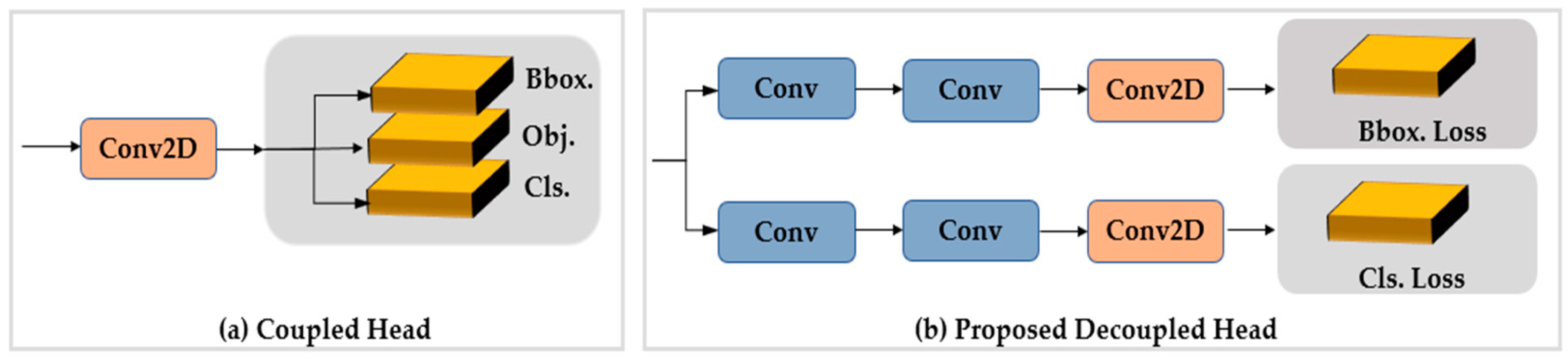
- Head
3.3. Network Testing and Evaluation
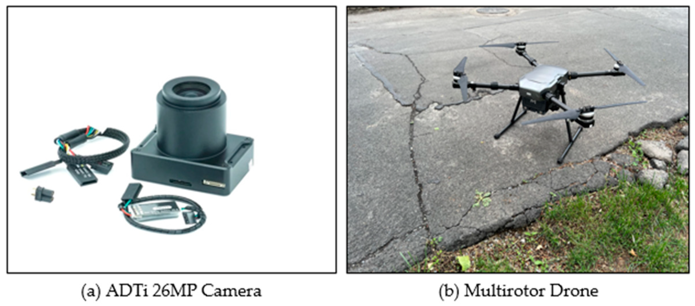
3.4. Platform and Data Acquisition
4. Experiment and Result
4.1. Data Preparation
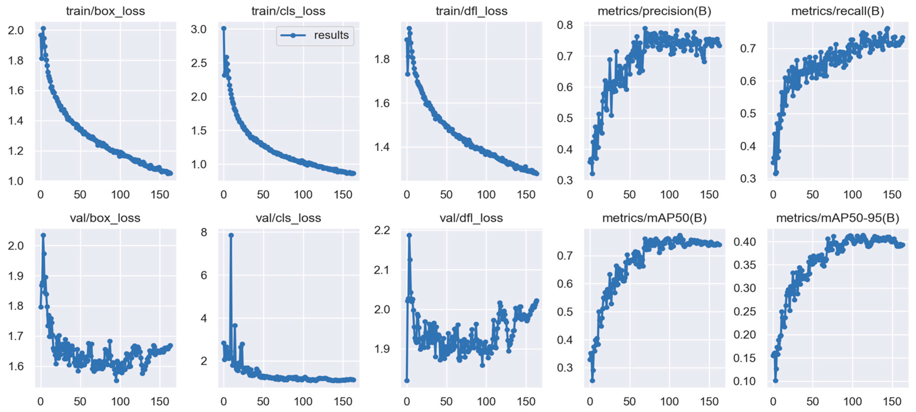
4.2. Model Implementation
4.3. Model Evaluation
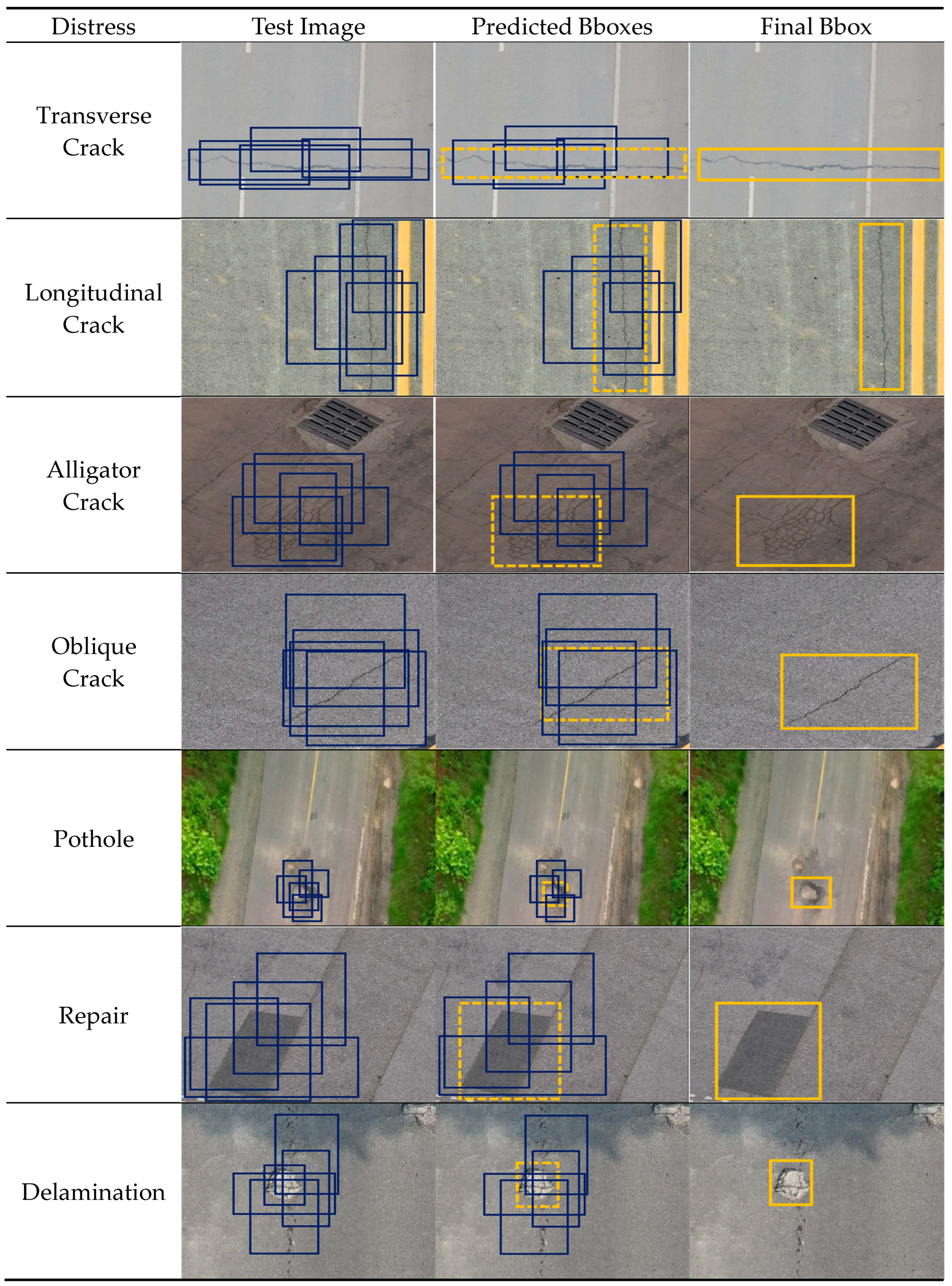
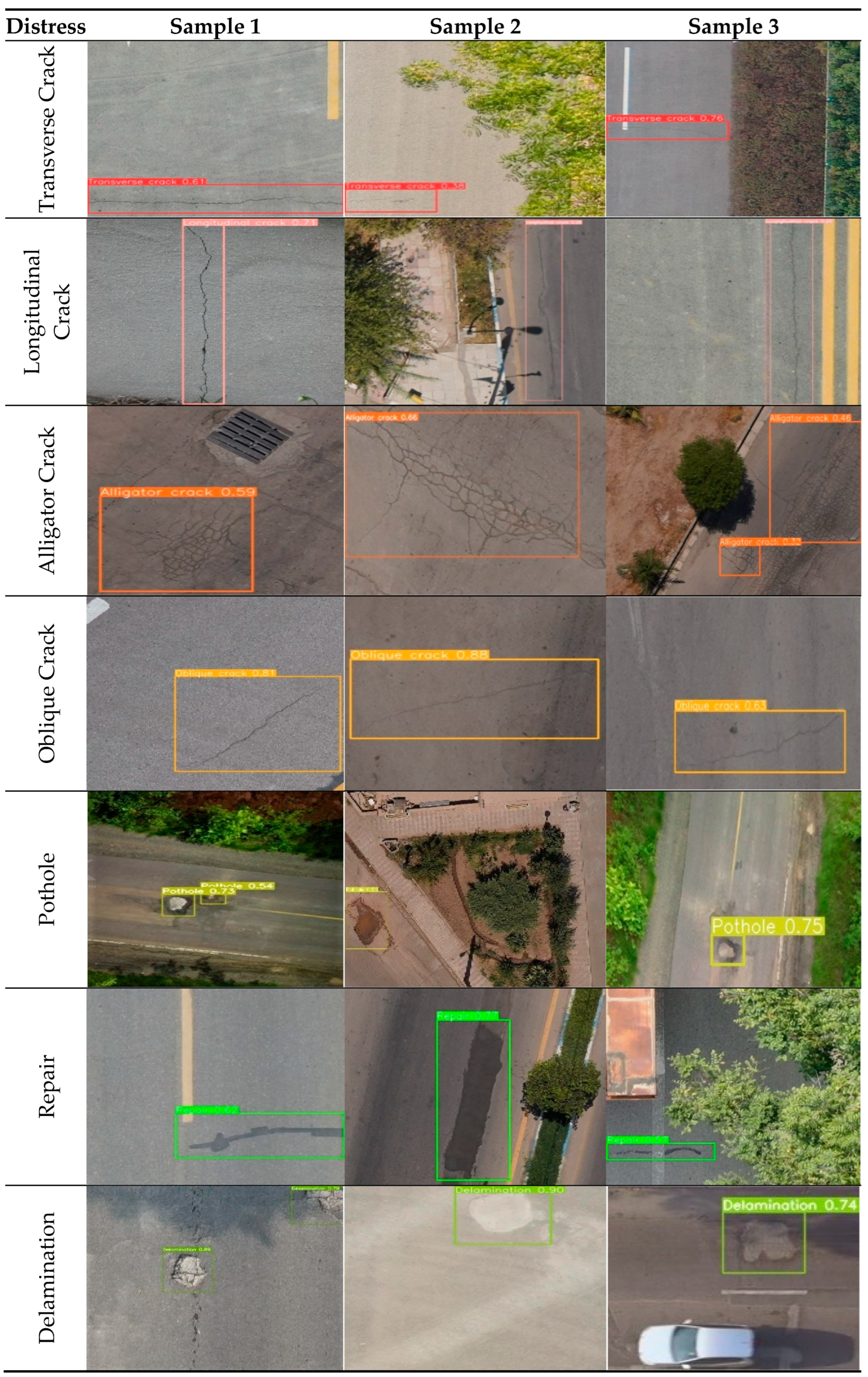
4.3.1. Test Results on UAV Aerial Imagery
4.3.2. Test Results on Terrestrial Imagery
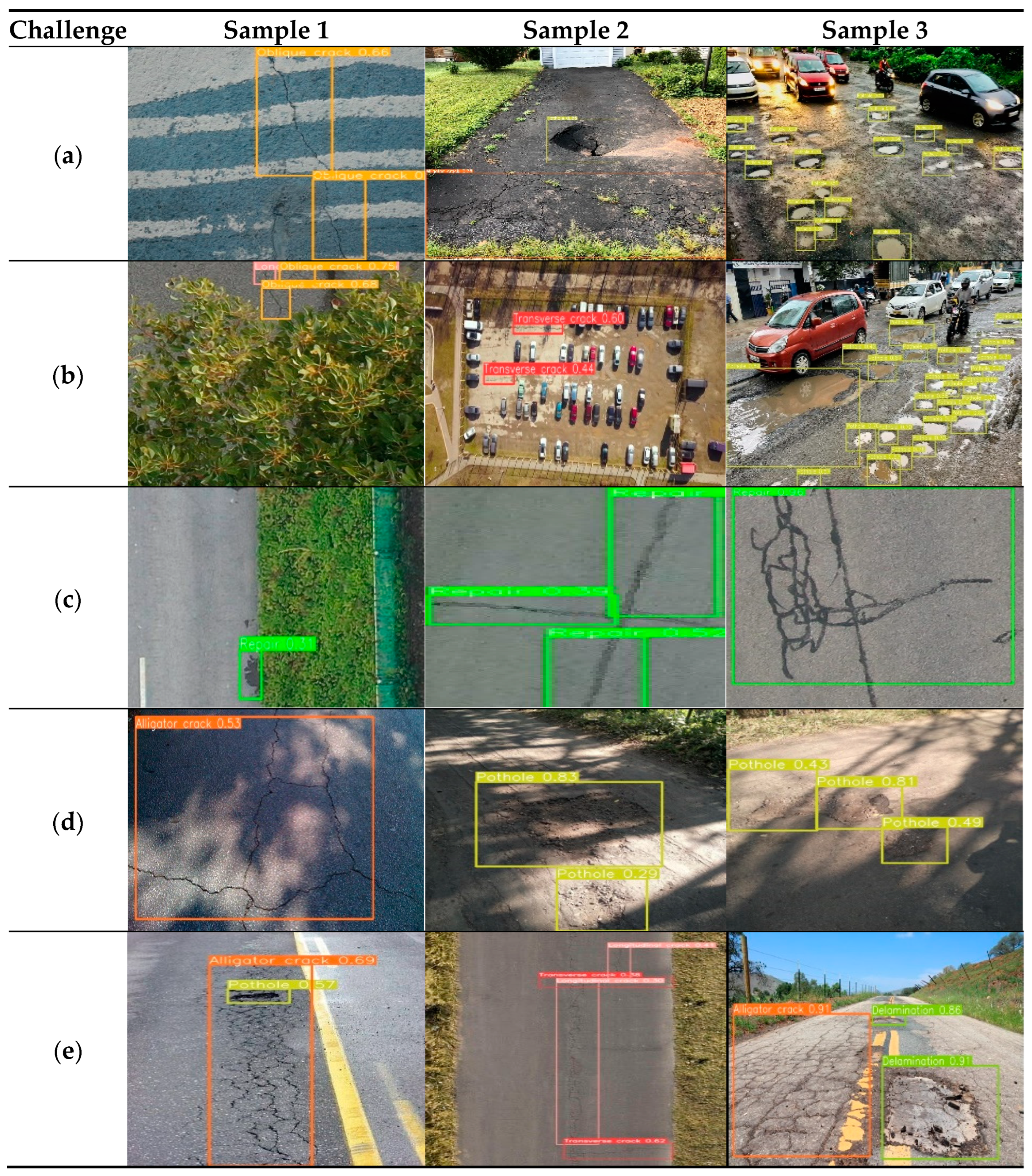
4.3.3. Addressing the Challenges of Network Implementation
5. Discussion
6. Conclusions
Author Contributions
Funding
Data Availability Statement
Conflicts of Interest
References
- Gopalakrishnan, K. Deep learning in data-driven pavement image analysis and automated distress detection: A review. Data 2018, 3, 28. [Google Scholar] [CrossRef]
- Eisenbach, M.; Stricker, R.; Seichter, D.; Amende, K.; Debes, K.; Sesselmann, M.; Ebersbach, D.; Stoeckert, U.; Gross, H.-M. How to get pavement distress detection ready for deep learning? A systematic approach. In Proceedings of the 2017 International Joint Conference on Neural Networks (IJCNN), Anchorage, AK, USA, 14–19 May 2017; pp. 2039–2047. [Google Scholar]
- Zhang, L.; Yang, F.; Zhang, Y.D.; Zhu, Y.J. Road crack detection using deep convolutional neural network. In Proceedings of the 2016 IEEE International Conference on Image Processing (ICIP), Phoenix, AZ, USA, 25–28 September 2016; pp. 3708–3712. [Google Scholar]
- Deng, J.; Singh, A.; Zhou, Y.; Lu, Y.; Lee, V.C.-S. Review on computer vision-based crack detection and quantification methodologies for civil structures. Constr. Build. Mater. 2022, 356, 129238. [Google Scholar] [CrossRef]
- Sarmiento, J.-A. Pavement distress detection and segmentation using YOLOv4 and DeepLabv3 on pavements in the Philippines. arXiv 2021, arXiv:2103.06467. [Google Scholar]
- Guo, L.; Li, R.; Jiang, B. A road surface damage detection method using yolov4 with pid optimizer. Int. J. Innov. Comput. Inform. Control. 2021, 17, 1763–1774. [Google Scholar]
- Doshi, K.; Yilmaz, Y. Road damage detection using deep ensemble learning. In Proceedings of the 2020 IEEE International Conference on Big Data (Big Data), Atlanta, GA, USA, 10–13 December 2020; pp. 5540–5544. [Google Scholar]
- Rasol, M.; Pais, J.C.; Pérez-Gracia, V.; Solla, M.; Fernandes, F.M.; Fontul, S.; Ayala-Cabrera, D.; Schmidt, F.; Assadollahi, H. GPR monitoring for road transport infrastructure: A systematic review and machine learning insights. Constr. Build. Mater. 2022, 324, 126686. [Google Scholar] [CrossRef]
- Pan, Y.; Zhang, L. Roles of artificial intelligence in construction engineering and management: A critical review and future trends. Autom. Constr. 2021, 122, 103517. [Google Scholar] [CrossRef]
- Miller, J.S.; Bellinger, W.Y. Distress Identification Manual for the Long-Term Pavement Performance Program; No. FHWA-RD-03-031; Federal Highway Administration. Office of Infrastructure Research and Development: McLean, VA, USA, 2003. [Google Scholar]
- Dixit, A.M.; Singh, H.; Meitzler, T. Soft computing approach to crack detection and FPGA implementation. Mater. Eval. 2010, 68, 1263–1272. [Google Scholar]
- Zhong, M.; Sui, L.; Wang, Z.; Hu, D. Pavement Crack Detection from Mobile Laser Scanning Point Clouds Using a Time Grid. Sensors 2020, 20, 4198. [Google Scholar] [CrossRef]
- Fang, F.; Li, L.; Gu, Y.; Zhu, H.; Lim, J.-H. A novel hybrid approach for crack detection. Pattern Recognit. 2020, 107, 107474. [Google Scholar] [CrossRef]
- Cha, Y.J.; Choi, W.; Suh, G.; Mahmoudkhani, S.; Büyüköztürk, O. Autonomous structural visual inspection using region-based deep learning for detecting multiple damage types. Comput. Aided Civ. Infrastruct. Eng. 2018, 33, 731–747. [Google Scholar] [CrossRef]
- Chmaj, G.; Selvaraj, H. Distributed processing applications for UAV/drones: A survey. In Progress in Systems Engineering: Proceedings of the Twenty-Third International Conference on Systems Engineering; Springer: Berlin/Heidelberg, Germany, 2015; pp. 449–454. [Google Scholar]
- Hassanalian, M.; Abdelkefi, A. Classifications, applications, and design challenges of drones: A review. Prog. Aerosp. Sci. 2017, 91, 99–131. [Google Scholar] [CrossRef]
- Sawrate, S.; Dhavalikar, M.N. A Review of Applications of Unmanned Aerial Vehicles in Science and Engineering. Int. J. Eng. Technol. Manag. Appl. Sci. 2016, 4, 150–155. [Google Scholar]
- Jordan, S.; Moore, J.; Hovet, S.; Box, J.; Perry, J.; Kirsche, K.; Lewis, D.; Tse, Z.T.H. State-of-the-art technologies for UAV inspections. IET Radar Sonar Navig. 2018, 12, 151–164. [Google Scholar] [CrossRef]
- Oliveira, H.; Correia, P.L. Automatic road crack segmentation using entropy and image dynamic thresholding. In Proceedings of the 2009 17th European Signal Processing Conference, Glasgow, UK, 24–28 August 2009; pp. 622–626. [Google Scholar]
- Zhao, H.; Qin, G.; Wang, X. Improvement of canny algorithm based on pavement edge detection. In Proceedings of the 2010 3rd International Congress on Image and Signal Processing, Yantai, China, 16–18 October 2010; pp. 964–967. [Google Scholar]
- Zhang, D.; Li, Q.; Chen, Y.; Cao, M.; He, L.; Zhang, B. An efficient and reliable coarse-to-fine approach for asphalt pavement crack detection. Image Vis. Comput. 2017, 57, 130–146. [Google Scholar] [CrossRef]
- Gao, W.; Zhang, X.; Yang, L.; Liu, H. An improved Sobel edge detection. In Proceedings of the 2010 3rd International Conference on Computer Science and Information Technology, Chengdu, China, 9–11 July 2010; pp. 67–71. [Google Scholar]
- Wang, X. Laplacian operator-based edge detectors. IEEE Trans. Pattern Anal. Mach. Intell. 2007, 29, 886–890. [Google Scholar] [CrossRef]
- Levkine, G. Prewitt, Sobel and Scharr gradient 5 × 5 convolution matrices. Image Process. Artic. Second Draft 2012. [Google Scholar]
- Cord, A.; Chambon, S. Automatic road defect detection by textural pattern recognition based on AdaBoost. Comput. Aided Civ. Infrastruct. Eng. 2012, 27, 244–259. [Google Scholar] [CrossRef]
- Subirats, P.; Dumoulin, J.; Legeay, V.; Barba, D. Automation of pavement surface crack detection using the continuous wavelet transform. In Proceedings of the 2006 International Conference on Image Processing, Atlanta, GA, USA, 8–11 October 2006; pp. 3037–3040. [Google Scholar]
- Abdel-Qader, I.; Abudayyeh, O.; Kelly, M.E. Analysis of edge-detection techniques for crack identification in bridges. J. Comput. Civ. Eng. 2003, 17, 255–263. [Google Scholar] [CrossRef]
- Prasanna, P.; Dana, K.J.; Gucunski, N.; Basily, B.B.; La, H.M.; Lim, R.S.; Parvardeh, H. Automated crack detection on concrete bridges. IEEE Trans. Autom. Sci. Eng. 2014, 13, 591–599. [Google Scholar] [CrossRef]
- Chen, J.-H.; Su, M.-C.; Cao, R.; Hsu, S.-C.; Lu, J.-C. A self organizing map optimization based image recognition and processing model for bridge crack inspection. Autom. Constr. 2017, 73, 58–66. [Google Scholar] [CrossRef]
- Valipour, P.S.; Golroo, A.; Kheirati, A.; Fahmani, M.; Amani, M.J. Automatic pavement distress severity detection using deep learning. Road Mater. Pavement Des. 2023, 2023, 1–17. [Google Scholar] [CrossRef]
- Zhu, J.; Zhong, J.; Ma, T.; Huang, X.; Zhang, W.; Zhou, Y. Pavement distress detection using convolutional neural networks with images captured via UAV. Autom. Constr. 2022, 133, 103991. [Google Scholar] [CrossRef]
- Hou, Y.; Dong, Y.; Zhang, Y.; Zhou, Z.; Tong, X.; Wu, Q.; Qian, Z.; Li, R. The Application of a Pavement Distress Detection Method Based on FS-Net. Sustainability 2022, 14, 2715. [Google Scholar] [CrossRef]
- Ali, L.; Alnajjar, F.; Khan, W.; Serhani, M.A.; Al Jassmi, H. Bibliometric Analysis and Review of Deep Learning-Based Crack Detection Literature Published between 2010 and 2022. Buildings 2022, 12, 432. [Google Scholar] [CrossRef]
- Simonyan, K.; Zisserman, A. Very deep convolutional networks for large-scale image recognition. arXiv 2014, arXiv:1409.1556. [Google Scholar]
- JitendraMalik, R.J.T. Rich feature hierarchies for accurate object detection and semantic segmentation. In Proceedings of the IEEE Conference on Computer Vision and Pattern Recognition, Columbus, OH, USA, 23–28 June 2014. [Google Scholar]
- Ren, S.; He, K.; Girshick, R.; Sun, J. Faster r-cnn: Towards real-time object detection with region proposal networks. Adv. Neural Inf. Process. Syst. 2015, 28, 91–99. [Google Scholar] [CrossRef]
- Long, J.; Shelhamer, E.; Darrell, T. Fully convolutional networks for semantic segmentation. In Proceedings of the IEEE Conference on Computer Vision and Pattern Recognition, New York, NY, USA, 15–17 June 1993; pp. 3431–3440. [Google Scholar]
- Liu, W.; Anguelov, D.; Erhan, D.; Szegedy, C.; Reed, S.; Fu, C.-Y.; Berg, A.C. Ssd: Single shot multibox detector. In Proceedings of the Computer Vision–ECCV 2016: 14th European Conference, Amsterdam, The Netherlands, 11–14 October 2016; Proceedings, Part I 14. pp. 21–37. [Google Scholar]
- Redmon, J.; Divvala, S.; Girshick, R.; Farhadi, A. You only look once: Unified, real-time object detection. In Proceedings of the IEEE Conference on Computer Vision and Pattern Recognition, Las Vegas, NV, USA, 27–30 June 2016; pp. 779–788. [Google Scholar]
- Skalski, P. How to Train YOLOv8 Object Detection on a Custom Dataset. Available online: https://blog.roboflow.com/how-to-train-yolov8-on-a-custom-dataset/ (accessed on 1 September 2022).
- Jacob Solawetz, F. What is YOLOv8? The Ultimate Guide. Available online: https://blog.roboflow.com/whats-new-in-yolov8/ (accessed on 1 September 2022).
- Samadzadegan, F.; Dadrass Javan, F.; Hasanlou, M.; Gholamshahi, M.; Ashtari Mahini, F. Automatic Road Crack Recognition Based on Deep Learning Networks from Uav Imagery. ISPRS Ann. Photogramm. Remote Sens. Spat. Inf. Sci. 2023, 10, 685–690. [Google Scholar] [CrossRef]
- SHRP2 Research Highlights Pavement Delamination Fixes. Available online: https://aashtojournal.org/2019/05/31/video-shrp2-research-highlights-pavement-delamination-fixes/#:~:text=%E2%80%9CDelamination%E2%80%9D%20refers%20to%20a%20condition,especially%20in%20the%20early%20stages (accessed on 1 September 2022).
- Yan, K.; Zhang, Z. Automated Asphalt highway pavement crack detection based on deformable single shot multi-box detector under a complex environment. IEEE Access 2021, 9, 150925–150938. [Google Scholar] [CrossRef]
- Yandell, W.; Pham, T. A fuzzy-control procedure for predicting fatigue crack initiation in asphaltic concrete pavements. In Proceedings of the 1994 IEEE 3rd International Fuzzy Systems Conference, Orlando, FL, USA, 26–29 June 1994; pp. 1057–1062. [Google Scholar]
- Tsubota, T.; Yoshii, T.; Shirayanagi, H.; Kurauchi, S. Effect of Pavement Conditions on Accident Risk in Rural Expressways. In Proceedings of the 2018 21st International Conference on Intelligent Transportation Systems (ITSC), Maui, HI, USA, 4–7 November 2018; pp. 3613–3618. [Google Scholar]
- Wang, M.; Sun, M.; Zhang, X.; Wang, Y.; Li, J. Mechanical behaviors of the thin-walled SHCC pipes under compression. In Proceedings of the 2015 International Conference on Transportation Information and Safety (ICTIS), Wuhan, China, 25–28 June 2015; pp. 797–801. [Google Scholar]
- Coenen, T.B.; Golroo, A. A review on automated pavement distress detection methods. Cogent Eng. 2017, 4, 1374822. [Google Scholar] [CrossRef]
- McGhee, K.H. Automated Pavement Distress Collection Techniques; Transportation Research Board: Washington, DC, USA, 2004; Volume 334. [Google Scholar]
- Song, L.; Wang, X. Faster region convolutional neural network for automated pavement distress detection. Road Mater. Pavement Des. 2021, 22, 23–41. [Google Scholar] [CrossRef]
- Silva, L.A.; Sanchez San Blas, H.; Peral García, D.; Sales Mendes, A.; Villarubia González, G. An architectural multi-agent system for a pavement monitoring system with pothole recognition in UAV images. Sensors 2020, 20, 6205. [Google Scholar] [CrossRef]
- Yang, C.; Chen, J.; Li, Z.; Huang, Y. Structural crack detection and recognition based on deep learning. Appl. Sci. 2021, 11, 2868. [Google Scholar] [CrossRef]
- Chun, P.-j.; Yamane, T.; Tsuzuki, Y. Automatic detection of cracks in asphalt pavement using deep learning to overcome weaknesses in images and GIS visualization. Appl. Sci. 2021, 11, 892. [Google Scholar] [CrossRef]
- Shaghouri, A.A.; Alkhatib, R.; Berjaoui, S. Real-time pothole detection using deep learning. arXiv 2021, arXiv:2107.06356. [Google Scholar]
- Shu, Z.; Yan, Z.; Xu, X. Pavement Crack Detection Method of Street View Images Based on Deep Learning. J. Phys. Conf. Ser. 2021, 1952, 022043. [Google Scholar] [CrossRef]
- Park, S.-S.; Tran, V.-T.; Lee, D.-E. Application of various yolo models for computer vision-based real-time pothole detection. Appl. Sci. 2021, 11, 11229. [Google Scholar] [CrossRef]
- Hu, G.X.; Hu, B.L.; Yang, Z.; Huang, L.; Li, P. Pavement crack detection method based on deep learning models. Wirel. Commun. Mob. Comput. 2021, 2021, 5573590. [Google Scholar] [CrossRef]
- Xu, X.; Zhao, M.; Shi, P.; Ren, R.; He, X.; Wei, X.; Yang, H. Crack Detection and Comparison Study Based on Faster R-CNN and Mask R-CNN. Sensors 2022, 22, 1215. [Google Scholar] [CrossRef]
- Fan, Z.; Lin, H.; Li, C.; Su, J.; Bruno, S.; Loprencipe, G. Use of Parallel ResNet for High-Performance Pavement Crack Detection and Measurement. Sustainability 2022, 14, 1825. [Google Scholar] [CrossRef]
- Whang, S.E.; Roh, Y.; Song, H.; Lee, J.-G. Data collection and quality challenges in deep learning: A data-centric AI perspective. VLDB J. 2023, 32, 791–813. [Google Scholar] [CrossRef]
- Tzutalin/LabelImg. Available online: https://github.com/heartexlabs/labelImg (accessed on 1 June 2015).
- Rath, S. YOLOv8 Ultralytics: State-of-the-Art YOLO Models. Available online: https://learnopencv.com/ultralytics-yolov8/ (accessed on 1 September 2022).
- Akyildiz, B. YOLOv8: A Comprehensive Framework for Object Detection, Instance Segmentation, and Image Classification. Available online: https://medium.com/@beyzaakyildiz/what-is-yolov8-how-to-use-it-b3807d13c5ce (accessed on 19 March 2023).
- Wang, C.-Y.; Liao, H.-Y.M.; Wu, Y.-H.; Chen, P.-Y.; Hsieh, J.-W.; Yeh, I.-H. CSPNet: A new backbone that can enhance learning capability of CNN. In Proceedings of the IEEE/CVF Conference on Computer Vision and Pattern Recognition Workshops, Seattle, WA, USA, 14–19 June 2020; pp. 390–391. [Google Scholar]
- He, K.; Zhang, X.; Ren, S.; Sun, J. Spatial pyramid pooling in deep convolutional networks for visual recognition. IEEE Trans. Pattern Anal. Mach. Intell. 2015, 37, 1904–1916. [Google Scholar] [CrossRef]
- Solawetz, J. What is YOLOv5? A Guide for Beginners. Available online: https://blog.roboflow.com/yolov5-improvements-and-evaluation/ (accessed on 20 May 2024).
- Elfwing, S.; Uchibe, E.; Doya, K. Sigmoid-weighted linear units for neural network function approximation in reinforcement learning. Neural Netw. 2018, 107, 3–11. [Google Scholar] [CrossRef]
- Zhang, C.; Xu, Y.; Shen, Y. Compconv: A compact convolution module for efficient feature learning. In Proceedings of the IEEE/CVF Conference on Computer Vision and Pattern Recognition, Nashville, TN, USA, 20–25 June 2021; pp. 3012–3021. [Google Scholar]
- Liu, H.; Sun, F.; Gu, J.; Deng, L. Sf-yolov5: A lightweight small object detection algorithm based on improved feature fusion mode. Sensors 2022, 22, 5817. [Google Scholar] [CrossRef]
- Xue, Z.; Lin, H.; Wang, F. A small target forest fire detection model based on YOLOv5 improvement. Forests 2022, 13, 1332. [Google Scholar] [CrossRef]
- Wang, K.; Liew, J.H.; Zou, Y.; Zhou, D.; Feng, J. Panet: Few-shot image semantic segmentation with prototype alignment. In Proceedings of the IEEE/CVF International Conference on Computer Vision, Seoul, Republic of Korea, 27 October–2 November 2019; pp. 9197–9206. [Google Scholar]
- Liu, S.; Qi, L.; Qin, H.; Shi, J.; Jia, J. Path aggregation network for instance segmentation. In Proceedings of the IEEE Conference on Computer Vision and Pattern Recognition, Long Beach, CA, USA, 15–20 June 2019; pp. 8759–8768. [Google Scholar]
- Redmon, J.; Farhadi, A. Yolov3: An incremental improvement. arXiv 2018, arXiv:1804.02767. [Google Scholar]
- OpenMMLab. Dive into YOLOv8: How Does This State-of-the-Art Model work? Available online: https://openmmlab.medium.com/dive-into-yolov8-how-does-this-state-of-the-art-model-work-10f18f74bab1 (accessed on 20 May 2024).
- Sharma, S.; Sharma, S.; Athaiya, A. Activation functions in neural networks. Towards Data Sci. 2017, 6, 310–316. [Google Scholar] [CrossRef]
- Kingma, D.P.; Ba, J. Adam: A method for stochastic optimization. arXiv 2014, arXiv:1412.6980. [Google Scholar]
- Ruder, S. An overview of gradient descent optimization algorithms. arXiv 2016, arXiv:1609.04747. [Google Scholar]
- Hosang, J.H.; Benenson, R.; Schiele, B. Learning Non-maximum Suppression. In Proceedings of the 2017 IEEE Conference on Computer Vision and Pattern Recognition (CVPR), Honolulu, HI, USA, 21–26 July 2017; pp. 6469–6477. [Google Scholar]
- Astor, Y.; Nabesima, Y.; Utami, R.; Sihombing, A.V.R.; Adli, M.; Firdaus, M.R. Unmanned aerial vehicle implementation for pavement condition survey. Transp. Eng. 2023, 12, 100168. [Google Scholar] [CrossRef]


| Device | ADTi 26MP Mapping Camera |
|---|---|
| Image Size (pixel) | 6192 × 4128 |
| Sensor Size (mm) | 23.4 × 15.6 |
| Focal Length (37.5 mm eq.) | 25 |
| FOV (degree) | 59 |
| Lens Distortion (%) | <0.5 |
| Max Effective ISO | 2749 |
| Shutter Speed (s) | 0.7 |
| Aperture | F/5.6 |
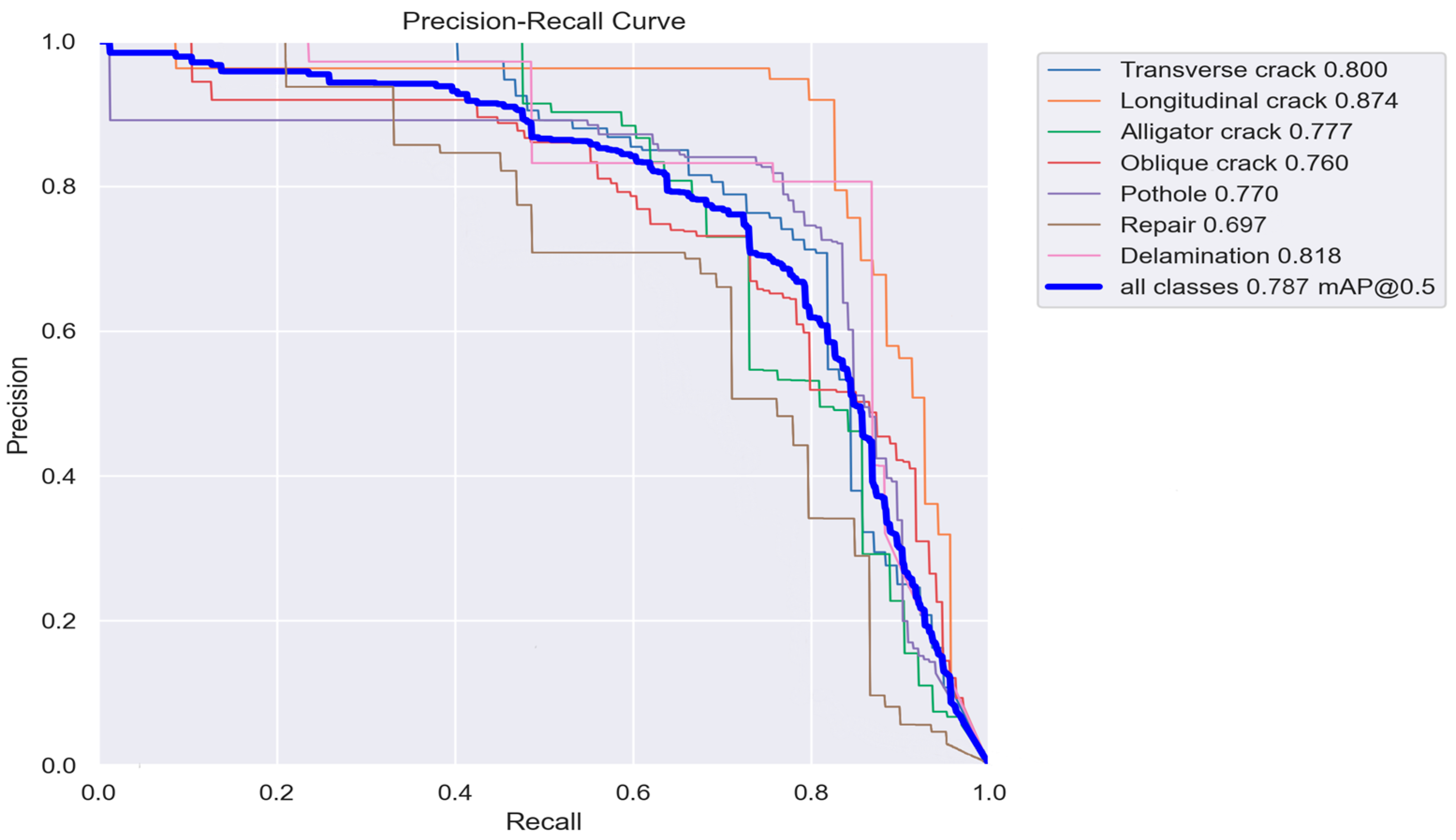
| Dataset | Precision % | Recall % | F1-Score % | mAP % | Accuracy % |
|---|---|---|---|---|---|
| Transverse Crack | 79 | 73 | 74 | 82 | - |
| Longitudinal Crack | 92 | 83 | 86 | 87 | - |
| Alligator Crack | 72 | 73 | 72 | 78 | - |
| Oblique Crack | 71 | 75 | 72 | 79 | - |
| Pothole | 78 | 77 | 76 | 77 | - |
| Repair | 60 | 69 | 64 | 70 | - |
| Delamination | 83 | 76 | 78 | 82 | - |
| Total | 77 | 75 | 74 | 79 | 81 |
Disclaimer/Publisher’s Note: The statements, opinions and data contained in all publications are solely those of the individual author(s) and contributor(s) and not of MDPI and/or the editor(s). MDPI and/or the editor(s) disclaim responsibility for any injury to people or property resulting from any ideas, methods, instructions or products referred to in the content. |
© 2024 by the authors. Licensee MDPI, Basel, Switzerland. This article is an open access article distributed under the terms and conditions of the Creative Commons Attribution (CC BY) license (https://creativecommons.org/licenses/by/4.0/).
Share and Cite
Samadzadegan, F.; Dadrass Javan, F.; Ashtari Mahini, F.; Gholamshahi, M.; Nex, F. Automatic Road Pavement Distress Recognition Using Deep Learning Networks from Unmanned Aerial Imagery. Drones 2024, 8, 244. https://doi.org/10.3390/drones8060244
Samadzadegan F, Dadrass Javan F, Ashtari Mahini F, Gholamshahi M, Nex F. Automatic Road Pavement Distress Recognition Using Deep Learning Networks from Unmanned Aerial Imagery. Drones. 2024; 8(6):244. https://doi.org/10.3390/drones8060244
Chicago/Turabian StyleSamadzadegan, Farhad, Farzaneh Dadrass Javan, Farnaz Ashtari Mahini, Mehrnaz Gholamshahi, and Francesco Nex. 2024. "Automatic Road Pavement Distress Recognition Using Deep Learning Networks from Unmanned Aerial Imagery" Drones 8, no. 6: 244. https://doi.org/10.3390/drones8060244
APA StyleSamadzadegan, F., Dadrass Javan, F., Ashtari Mahini, F., Gholamshahi, M., & Nex, F. (2024). Automatic Road Pavement Distress Recognition Using Deep Learning Networks from Unmanned Aerial Imagery. Drones, 8(6), 244. https://doi.org/10.3390/drones8060244