Article

Attitude Control of Small Fixed−Wing UAV Based on Sliding Mode and Linear Active Disturbance Rejection Control

1
School of Automation and Information Engineering, Sichuan University of Science and Engineering, Yibin 644000, China
2
Artificial Intelligence Key Laboratory of Sichuan Province, Yibin 644000, China
3
School of Electronic and Electrical Engineering, Civil Aviation Flight University of China, Deyang 618307, China
*
Author to whom correspondence should be addressed.
Drones 2024, 8(7), 318; https://doi.org/10.3390/drones8070318
Submission received: 15 May 2024 / Revised: 3 July 2024 / Accepted: 4 July 2024 / Published: 11 July 2024

Abstract

:
A combined control method integrating Linear Active Disturbance Rejection Control (LADRC) and Sliding Mode Control (SMC) is proposed to mitigate model uncertainty and external disturbances in the attitude control of fixed−wing unmanned aerial vehicles (UAVs). First, the mathematical and dynamic models of a small fixed−wing UAV are constructed. Subsequently, a Linear Extended State Observer (LESO) is designed to accurately estimate the model uncertainties and unidentified external disturbances. The LESO is then integrated into the control side to enable the SMC to enhance the control system’s anti−interference performance due to its insensitivity to variations in−system parameters. The system’s stability is proven using the Lyapunov stability theory. Finally, simulations comparing the classical LADRC and the newly developed SMC−LADRC reveal that the latter exhibits strong robustness and anti−interference capabilities in scenarios involving model uncertainty, external disturbances, and internal disturbances, confirming the effectiveness of this control method.

1. Introduction

Fixed−wing UAVs offer advantages such as long endurance, a large cruising range, a low cost, and strong information perception. As highly maneuverable vehicles capable of carrying various instruments to complete specific tasks, they are widely used in unmanned freight transportation systems [1], crop protection [2], ocean monitoring [3], forest fire monitoring [4], surveying and mapping [5], and other fields. However, designing control systems for fixed−wing UAVs is challenging despite their numerous advantages. The complexity arises from the extensive assumptions needed during the analysis of fixed−wing UAVs, such as simplifying the UAV as a rigid body and assuming constant ground acceleration. These simplifications inevitably lead to the development of approximate mathematical and dynamic models, resulting in discrepancies between the actual and ideal models. Consequently, the uncertainty in system parameters is primarily attributed to the mismatch between real−world dynamics and the simplified assumptions made during modeling.
The characteristics of fixed−wing UAVs, such as nonlinearity, strong coupling, and underactuation, present multiple challenges in designing their control systems. In recent decades, significant scholarly attention has been devoted to the flight control of fixed−wing UAVs, resulting in extensive research aimed at enhancing flight control systems’ efficacy. Various methodologies have been explored and implemented to optimize the flight control mechanisms governing fixed−wing UAV operations. These include PID control [6], LQR control [7], backstepping control [8], adaptive control [9], H∞ control [10], sliding mode control [11], and others. Most existing control methods rely heavily on model accuracy. In the presence of uncertain disturbances, accurately modeling the system becomes impossible, leading to the control system’s inability to effectively suppress disturbances. ADRC is a control strategy that does not depend on the exact mathematical model of the control target [12]. ADRC considers unknown factors, uncertain states, coupling, and external perturbations in the system as total disturbances. It treats them as the extended state of the system, using an Extended State Observer (ESO) for online estimation. By applying feedforward compensation, it converts the system into an integral series−type structure, then uses feedback control law to achieve strong anti−interference capabilities and a dynamic response. The conventional ADRC is nonlinear, requires numerous parameter adjustments, and is difficult to apply in engineering. Professor Zhiqiang Gao introduced the concept of bandwidth in ADRC, proposing LADRC [13]. Unlike ADRC, LADRC omits the tracking differentiator and linearizes the ESO and nonlinear state error feedback. Simplifying many parameters into observation bandwidth and control bandwidth makes tuning the control parameters easier.
Reference [14] introduces a novel control design approach utilizing enhanced ADRC to address the challenges of fixed−wing UAV attitude and airspeed control amidst model uncertainty and external perturbations. The methodology incorporates a RBF neural network ESO to effectively estimate and counteract both internal and external uncertainties within the system. Additionally, the implementation of adaptive sliding mode control with nonlinear state error feedback enhances the controller response speed and minimizes the complexities associated with parameter tuning. In Reference [15], a novel control strategy termed Fractional−Order LADRC (FOLADRC) is introduced to address control challenges in the conversion mode of a dual quadrotor. FOLADRC combines the strengths of Fractional−Order PID (FOPID) and LADRC to enhance the control performance. To mitigate the complexities associated with parameter tuning in FOLADRC and meet the demands for control precision and speed, an enhanced sparrow search algorithm is employed. Simulation and experimental evaluations demonstrate that the FOLADRC technique effectively mitigates system uncertainties and external disturbances, showcasing notable advantages over conventional PID and LADRC methods. Reference [16] addresses the landing control problem of a variable mass UAV by incorporating LADRC in the controller design. LADRC is utilized to counteract unknown disturbances within the system, enhancing the control performance. The simulation results demonstrate that the proposed control strategy enables the rapid and precise tracking of forward speed and flight trajectory commands, showcasing robustness to model uncertainty. Reference [17] introduces a novel approach to quadrotor UAV attitude control known as Fuzzy−LADRC. This method leverages the adaptability of fuzzy controllers and the perturbation rejection capabilities of LADRC to address the complexities of nonlinear and interconnected systems. Simulation studies compare and evaluate the performance of four controllers, indicating that the proposed control strategy enhances the UAV’s response speed and interference rejection capabilities, demonstrating its effectiveness in improving control performance. In Reference [18], a novel control strategy for unmanned quadcopter altitude attitude control is introduced, leveraging the Adaptive Sliding Mode−ADRC (ASM−ADRC). This approach amalgamates the benefits of adaptive SMC for precise reference trajectory tracking with the capabilities of ADRC to mitigate parameter uncertainties and external disturbances. Simulation evaluations showcase the proposed method’s enhanced robustness to model uncertainties and external perturbations while notably reducing chattering effects, thereby improving the overall control performance. Reference [19] tackles the challenge of attitude control in a moving mass−driven fixed−wing UAV (MFUAV) by employing LADRC to eliminate internal coupling and counter the external disturbances affecting the MFUAV. The simulation results validate the method’s efficacy, demonstrating robustness in the attitude tracking control of the MFUAV by effectively addressing internal and external disturbances. Reference [20] introduces a nonlinear flight control technique utilizing an ESO for the flight control of fixed−wing UAVs. The ESO serves a dual function by estimating not only the state variables of the UAV but also perturbations, uncertainties, nonlinear dynamics, and observation errors. By dynamically adjusting the gains of the observer and the controller, the method aims to eliminate the influence of perturbations on the dynamic characteristics of the UAV, thereby enhancing the control performance. In Reference [21], the design process of quadrotor UAV controllers is divided into two steps to ensure the trajectory tracking performance under external disturbances and model uncertainties. Firstly, the dynamic model of the quadrotor UAV is decomposed into two cascaded subsystems controlling the UAV’s angles and angular velocities through first−order ADRC. Secondly, an additional high−gain design parameter is introduced, resulting in the construction of a new position subsystem backstepping sliding mode control scheme. Reference [22] focuses on quadrotor payload UAVs with varying masses, and designs a mass−adaptive control method combining robust SMC and LADRC. SMC enhances the robustness of the controller and addresses the low control precision issue caused by bandwidth limitations in LADRC. LESO is capable of the real−time estimation of the system’s external and internal disturbances, subsequent compensation for the total disturbance through a PD controller, and the introduction of adaptive control parameters in real−time control in LADRC.
Inspired by the literature, this paper proposes a fixed−wing UAV attitude control method based on SMC−LADRC. The main contributions of this paper can be summarized as follows:
  • An attitude control method based on SMC−LADRC is proposed, effectively addressing the effects of external disturbances and model uncertainty on attitude control. The control framework is shown in Figure 1.
  • To estimate external disturbances and the model uncertainty, a LESO in LADRC is designed to obtain the estimated values of the attitude angle, attitude angular velocity, and total disturbance of the fixed−wing UAV. This observer compensates for the total disturbance within the controller.
  • Traditional LADRC generally uses a linear combination for the error feedback law. When the system is affected by strong wind, the controller’s effectiveness is significantly reduced, thereby impacting the anti−interference and robustness of the UAV system. Unlike Reference [21], which used LADRC for attitude control and backstepping SMC for position control, and Reference [22], which employed a series control consisting of SMC and LADRC, this paper substitutes SMC for the error feedback law in LADRC. This approach leverages SMC’s insensitivity to system parameter variations, enhancing the control system’s anti−interference performance and meeting the need for a fast response.
  • The Trace Differentiator (TD) is introduced to track the desired input, aiming to minimize overshoot and enhance the controller’s robustness. By incorporating the TD, the system output can achieve the more stable tracking of the desired input, leading to an improved overall performance.
The rest of the paper is organized as follows: In Section 2, we develop a mathematical model of a fixed−wing UAV using the quaternion method. In Section 3, we develop sliding mode active interference suppression controllers for each of the three attitude angles and demonstrate the stability of the controllers. In Section 4, through comparative simulation experiments between LADRC and SMC−LADRC, we verify that the SMC−LADRC controller has a faster response speed and better interference suppression capabilities compared to LADRC. Finally, Section 5 concludes the paper.

2. Dynamics Model of Fixed−Wing UAV

Fixed−wing UAVs change their attitude by adjusting the elevator, ailerons, and rudder. During UAV flight, various external forces act on the vehicle, including gravity, engine thrust, and aerodynamic forces. These different forces need to be represented in their respective coordinate systems. To establish the mathematical model and dynamic equations of the UAV, the variables defined in different coordinate systems must be converted to a common coordinate system.
In deriving the rigid body equations of motion for the UAV, the following assumptions are made to simplify the computational process:
  • The Earth’s rotation is stagnant and the curvature of the Earth is zero.
  • The fuselage of the UAV, centered on a central axis plane, is perfectly symmetrical.
  • The acceleration of gravity remains constant, independent of position in space.
  • The airframe of a fixed−wing UAV is considered rigid and does not deform or vibrate due to changes in force.
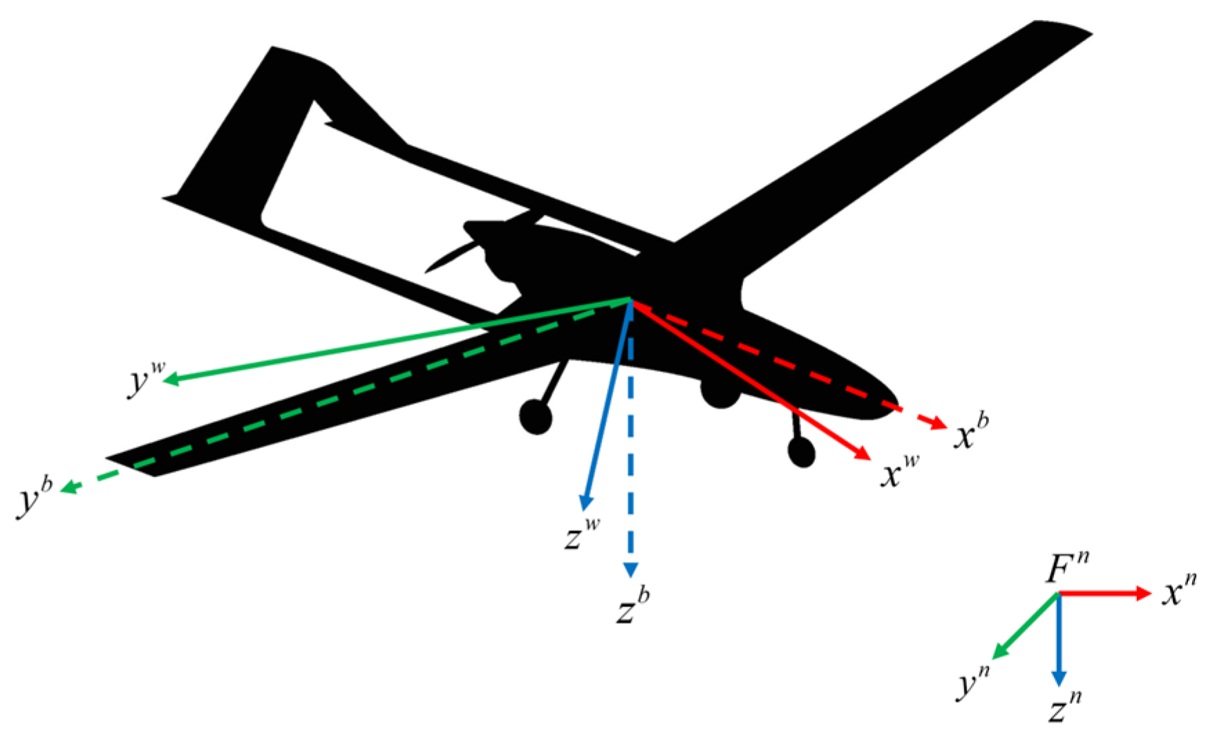
In order to describe the equations of rotation and translational dynamics for a fixed−wing UAV, multiple reference coordinate systems are used. The geographic coordinate system of the fixed−wing UAV, the airframe coordinate system, and the airflow velocity coordinate system are introduced:
  • Terrestrial inertial coordinate system F n ( o n x n y n z n ): using the starting position of the UAV as the coordinate origin, x n points in a northerly direction, y n points in an easterly direction, and z n points to the core.
  • Coordinate system of airframe F b ( o b x b y b z b ): the origin is at the center of mass of the UAV, x b points towards the head along the longitudinal axis of the UAV structure, y b is perpendicular to the x b pointing in the direction of the right flank, and z b is in the plane of symmetry of the body, vertically o b x b downwards.
  • Air coordinate system F w ( o w x w y w z w ): the origin is at the center of mass of the UAV, x w points in the direction of the UAV’s speed, z w is in the plane of symmetry of the airplane, perpendicular to the x w , and y w is perpendicular to the z w o w x w , rightwards. The relationship between these three coordinate systems is shown in Figure 2.
Quaternions and Euler angles are commonly used to describe the motion attitude of UAVs in 3D space. The mathematical modeling of UAVs with Euler angles has singularities and fails when the angle of the UAV changes too much, and a large number of trigonometric operations occur when solving the controller, which increases the complexity and difficulty of the design. Compared with Euler angles, quaternions do not produce ambiguity phenomena when describing the attitude and are expressed in a concise way. According to the literature [23], the nonlinear model of a fixed−wing UAV can be expressed by the quaternion method as follows:
p ˙ n = ( e 1 2 + e 0 2 e 2 2 e 3 2 ) u + 2 ( e 1 e 2 e 3 e 0 ) v + 2 ( e 1 e 3 + e 2 e 0 ) w
p ˙ e = 2 ( e 1 e 2 + e 3 e 0 ) u + ( e 2 2 + e 0 2 e 1 2 e 3 2 ) v + 2 ( e 2 e 3 e 1 e 0 ) w
p ˙ d = 2 ( e 1 e 3 e 2 e 0 ) u 2 ( e 2 e 3 + e 1 e 0 ) v ( e 3 2 + e 0 2 e 1 2 e 2 2 ) w
u ˙ = r v q w + 2 g ( e 1 e 3 e 2 e 0 ) + ρ V a 2 S 2 m ( C D 0 + C D α α + C D q c q 2 V a + C D δ e δ e ) + ρ S p r o p C p r o p 2 m [ ( k m o t o r δ t ) 2 V a 2 ]
v ˙ = p w r u + 2 g ( e 2 e 3 + e 1 e 0 ) + ρ V a 2 S 2 m ( C Y 0 + C Y β β + C Y p b p 2 V a + C Y r b r 2 V a + C Y δ a δ a + C Y δ r δ r )
w ˙ = q u p v + g ( e 3 2 + e 0 2 e 1 2 e 2 2 ) + ρ V a 2 S 2 m ( C L 0 + C L α α + C L q c q 2 V a + C L δ e δ e )
p ˙ = Γ 1 p q Γ 2 q r + 1 2 ρ V a 2 S b ( C p 0 + C p β β + C p p b p 2 V a + C p r b r 2 V a + C p δ a δ a + C p δ r δ r )
q ˙ = Γ 5 p r Γ 6 ( p 2 r 2 ) + ρ V a 2 S c 2 J y ( C m 0 + C m α α + C m q c q 2 V a + C m δ e δ e )
r ˙ = Γ 7 p q Γ 1 q r + 1 2 ρ V a 2 S b ( C r 0 + C r β β + C r p b p 2 V a + C r r b r 2 V a + C r δ a δ a + C r δ r δ r )
e ˙ 0 = 1 2 ( p e 1 + q e 2 + r e 3 )
e ˙ 1 = 1 2 ( p e 0 + r e 2 q e 3 )
e ˙ 2 = 1 2 ( q e 0 r e 1 + p e 3 )
e ˙ 3 = 1 2 ( r e 0 + q e 1 + p e 2 )
where p n , p e and p d are the position components of the UAV in the inertial coordinate system along the due east, due north and downward directions, respectively; u , v , w and p , q , r are defined in the body coordinate system and represent linear and angular velocities, respectively; m is the mass of the UAV; ρ is the density of air; S p r o p is the propeller area; C p r o p is the thruster aerodynamic coefficient; k m o t o r is the motor efficiency constant; S is the wing area; b is the wing span; V a is the airspeed and V a = u 2 + v 2 + w 2 ; α is the angle of attack and α = arctan w u ; β is the side slip angle and β = arcsin v V a ; c is the average aerodynamic chord length of the wing; C D 0 , C D α , C D q and C D δ e are the drag coefficients; C Y 0 , C Y β , C Y p , C Y r , C Y δ a and C Y δ r are the lateral force coefficients; C L 0 , C L α , C L q and C L δ e are the lift coefficients; C p 0 , C p β , C p p , C p r , C p δ a and C p δ r are the rolling moment coefficients; C m 0 , C m α , C m q and C m δ e are the pitching moment coefficients; C r 0 , C r β , C r p , C r r , C r δ a and C r δ r are the yaw moment coefficients; δ a is the UAV aileron control signal; δ e is the UAV elevator control signal; δ r is the UAV rudder control signal; and δ t is the UAV engine control signal. The aerodynamic coefficients describing the roll and yaw moments are given by the following equation:
C P 0 = Γ 3 C l 0 + Γ 4 C n 0 , C P β = Γ 3 C l β + Γ 4 C n β
C P p = Γ 3 C l p + Γ 4 C n p , C P r = Γ 3 C l r + Γ 4 C n r
C P δ a = Γ 3 C l δ a + Γ 4 C n δ a , C P δ r = Γ 3 C l δ r + Γ 4 C n δ r
C r 0 = Γ 4 C l 0 + Γ 8 C n 0 , C r β = Γ 4 C l β + Γ 8 C n β
C r p = Γ 4 C l p + Γ 8 C n p , C r r = Γ 4 C l r + Γ 8 C n r
C r δ a = Γ 4 C l δ a + Γ 8 C n δ a , C r δ r = Γ 4 C l δ r + Γ 8 C n δ r
where J x , J y , J z , J x z is the moment of inertia of the UAV, and C l i ( i = 0 , β , p , r , δ a , δ r ) , C n j ( j = 0 , β , p , r , δ a , δ r ) is the aerodynamic coefficient describing the roll moment and yaw moment, which can be calculated using the rotational inertia of the UAV itself with the following formula: Γ 1 = J x z ( J x J y + J z ) Γ , Γ 2 = J z ( J z J y ) + J x z 2 Γ , Γ 3 = J z Γ , Γ 4 = J x z Γ , Γ 5 = J z J x Γ , Γ 6 = J x z Γ , Γ 7 = J x ( J x J y ) + J x z 2 Γ , Γ 8 = J x Γ , Γ = J x J z J x z 2 .

3. UAV Attitude Controller Design

3.1. Linear Active Disturbance Rejection Control Design

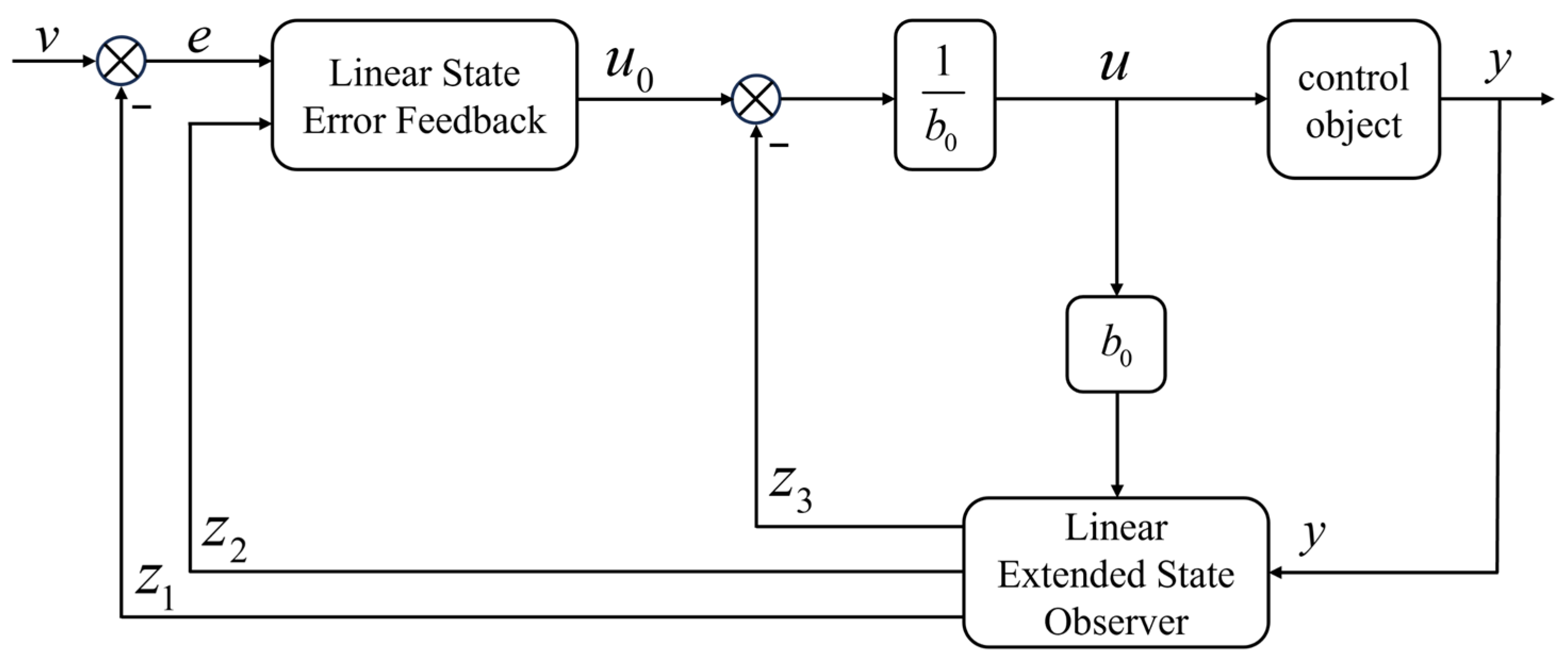
ADRC is a method based on disturbance observation and compensation that aims to actively suppress and robustly control system disturbances. It achieves system disturbance rejection by observing and estimating system uncertainties and external disturbances and then compensating for them at the control input. LADRC is characterized by high accuracy, a rapid response, and strong resilience to interference [13]. In LADRC, inter−channel coupling in attitude control is treated as an uncertain internal disturbance, which is estimated in real−time by the LESO within the controller. The LESO aids in estimating the total disturbance, encompassing both internal unmodeled dynamics and external uncertainties, contributing to effective disturbance rejection in the control system. In the context of LADRC, there is no requirement to decouple all channels of the system, as each channel can be controlled independently. Furthermore, LADRC does not rely on the precise mathematical model of the system; instead, it is primarily linked to the system’s order. The LADRC controller is adaptable and robust, allowing for the effective control of each channel without the need for complex decoupling procedures. Below, the LADRC controller is presented as an illustration of the roll channel’s control. Figure 3 shows the block diagram of the second−order LADRC controller.
To facilitate the observer design, the state variables x 1 = ϕ , x 2 = ϕ ˙ . Expand the roll channel to the following:
x ˙ 1 = x 2 x ˙ 2 = f + b ϕ u y = x 1
where f is the total disturbance, and b ϕ is the control volume compensation factor. The total disturbance is the sum of all disturbances in the traversing roll channel, which mainly consists of coupling between the attitude channels, model uncertainty, sensor noise, and external disturbances.
The aim of LADRC is to expand the total disturbance f existing in the system into a new state variable, estimate the total disturbance f of the system by constructing a LESO, and finally eliminate it in the controller.
Therefore, the expansion state variable x 3 = f is chosen so that Equation (20) can be written as follows:
x ˙ 1 = x 2 x ˙ 2 = x 3 + b ϕ u x ˙ 3 = f ˙ y = x 1
Its matrix form is as follows:
x ˙ = A Z + B u + E f y = C Z
where A = 0 1 0 0 0 1 0 0 0 , B = 0 b ϕ 0 T , C = 1 0 0 , E = 0 0 1 T .
The designed LESO is shown in Equation (23):
z ˙ 1 ϕ = z 2 ϕ l 1 ( z 1 ϕ ϕ ) z ˙ 2 ϕ = z 3 ϕ l 2 ( z 1 ϕ ϕ ) + b ϕ u ϕ z ˙ 3 ϕ = l 3 ( z 1 ϕ ϕ )
where l 1 , l 2 , l 3 is the observer gain, z 1 ϕ is the estimate of the roll angle, z 2 ϕ is the estimate of the roll angular velocity, and z 3 ϕ is the estimate of the total disturbance. The observer gain is parameterized by arranging all eigenvalues within the observation bandwidth. By doing so, the observer gain can be determined from its characteristic equation.
λ 0 ( s ) = s 3 + l 1 s 2 + l 2 s + l 3 = ( s + ω 0 ) 3
where ω 0 is the bandwidth of the observer, and l 1 = 3 ω 0 , l 2 = 3 ω 0 2 , l 3 = ω 0 3 . An increase in ω 0 helps to improve the control accuracy of the LADRC, but too high a ω 0 can lead to oscillations.
At this point, the state variable observations of the system and the total disturbance observations of the system can be estimated. The elimination of the disturbances is then performed in the controller:
u 1 = k p ( ϕ d z 1 ϕ ) + k d z 2 ϕ
u ϕ = u 1 z 3 ϕ b ϕ
where ω c is the controller bandwidth and k p = ω c 2 , k d = 2 ω c ; ϕ d is the desired roll angle of the input; and u ϕ is the output of the LADRC controller.

3.2. SMC−LADRC Controller Design

The error feedback law in LADRC is typically structured as a linear combination. However, during periods of significant wind disturbances, the controller’s effectiveness diminishes, thereby compromising the anti−interference capabilities and robustness of the UAV system. To address this issue, this paper proposes replacing the error feedback law in LADRC with SMC. SMC is chosen for its insensitivity to system parameter variations, enhancing the control system’s anti−interference performance and responsiveness. Figure 4 illustrates the block diagram of SMC−LADRC.
Taking the roll angle as an example, the Trace Differentiator is shown in Equation (31):
v 1 ( t + 1 ) = v 1 ( t ) + h v 2 ( t ) v 2 ( t + 1 ) = v 2 ( t ) + h f h a n ( v 1 v d , v 2 , r , h )
f h a n ( · ) is the optimal control synthesis function and its expression is shown in Equation (32):
d = r h d 0 = h d y = x 1 + h x 2 a 0 = d 2 + 8 r y a = x 2 + ( a 0 d ) 2 s i g n ( y ) , y > d 0 x 2 + y h , y d 0 f h a n = r s i g n ( a ) , a > d r a d , a d
where r is the fast factor, h is the sampling time, v 1 ( t ) is the tracking signal of the desired signal, and v 2 ( t ) is the tracking signal of the differential of the desired signal.
Since the LESO obtains an estimate of the total disturbance and then compensates for it on the control side, an appropriate SMC convergence rate is used to design the control rate so that the control error converges to 0. The state equation of the system after disturbance compensation can be expressed as follows:
x ˙ 1 = x 2 x ˙ 2 = b ϕ u 1 z 3 ϕ b ϕ + f = u 1 + ( f z 3 ϕ )
where f is the total disturbance of the system, z 3 ϕ is the estimated value of the total disturbance, f z 3 ϕ is the uncompensated disturbance of the system, and f z 3 ϕ < ρ . The desired input for defining the roll angle is ϕ d . The estimation error of LESO is e = z 1 ϕ ϕ d , e ˙ = z 2 ϕ ϕ ˙ d , e ¨ = x ˙ 2 ϕ ¨ d = u 1 + ( f z 3 ϕ ) ϕ ¨ d = u 1 ϕ ¨ d . Design the sliding mold surface as follows:
s ϕ = c ϕ e + e ˙
where c ϕ > 0. Derive Equation (30):
s ˙ ϕ = c ϕ e ˙ + e ¨ = c ϕ e ˙ + ( f z 3 ϕ ) + u 1 ϕ ¨ d
Use the exponential convergence rate: s ˙ = ε · s i g n ( s ) k s :
u 1 = c ϕ e ˙ + ϕ ¨ d ε ϕ · s i g n ( s ϕ ) k ϕ s ϕ
where ε ϕ > 0 , k ϕ > 0 .
Therefore, the controllers for the roll, pitch, and yaw channels are shown in Equation (33):
v 1 ( t + 1 ) = v 1 ( t ) + h v 2 ( t ) v 2 ( t + 1 ) = v 2 ( t ) + h f h a n ( v 1 v d , v 2 , r , h ) z ˙ 1 i = z 2 i 3 ω i ( z 1 i i ) z ˙ 2 i = z 3 i 3 ω i 2 ( z 1 i i ) + b i u i z ˙ 3 i = ω i 3 ( z 1 i i ) u 3 = c i e ˙ + i ¨ d ε i · s i g n ( s i ) k i s i u i = u 3 z 3 i b i
where i = ϕ , θ , φ .
Traditional sliding mode controllers often employ a sign function that is not continuous, resulting in discontinuous controller commands and causing a chattering effect that impacts system stability. To mitigate this issue, this paper proposes using a saturation function instead of the sign function in controller design to ensure the continuity of the controlled variable.
s i g n ( s ) s a t ( s ) = 1   s   >   Δ ; s Δ | s |     Δ ; 1 s   <   Δ ;
where Δ = 0.2.

3.3. Stability Analysis

Taking the roll angle as an example, the Lyapunov function is constructed such that V = 1 2 s ϕ 2 0 can be obtained:
V ˙ = s ϕ s ˙ ϕ = s ϕ [ c ϕ e ˙ ϕ + ( f z 3 ϕ ) + u 1 ϕ ¨ d ] = s ϕ [ ( f z 3 ϕ ) ε ϕ · s i g n ( s ϕ ) k ϕ s ϕ ] = s ϕ ( f z 3 ϕ ) ε ϕ · s i g n ( s ϕ ) s ϕ k ϕ s ϕ 2 = s ϕ ( f z 3 ϕ ) ε ϕ | s ϕ | k ϕ s ϕ 2 k ϕ s ϕ 2 | s ϕ | ( ε ϕ ρ )
where ε ϕ ρ can be guaranteed to be V ˙ < 0 ; when s ϕ 0 and e ˙ = 0 are obtained,
e ¨ = u 1 + ( f z 3 ϕ ) ϕ ¨ d = c ϕ e ˙ ε ϕ · s i g n ( s ϕ ) k ϕ s ϕ + ( f z 3 ϕ ) = ε ϕ · s i g n ( s ϕ ) k ϕ s ϕ + ( f z 3 ϕ )
e ¨ < ρ ε ϕ k ϕ s ϕ < 0 , when s ϕ > 0 ; and e ¨ = ρ + ε ϕ + k ϕ s ϕ > 0 , when s ϕ < 0 . Thus e ˙ = 0 cannot be maintained, and e ˙ always converges to a state of e ˙ 0 . Thus, ensuring that the state will converge to the sliding mode surface, the designed SMC−LADRC is Lyapunov convergent.

4. Simulation and Discussion

In this section, the designed SMC−LADRC is simulated using a nonlinear fixed−wing UAV model constructed in MATLAB. The SMC−LADRC is separately designed and simulated for roll, pitch, and yaw channels to analyze its performance. Table 1 presents the physical parameters of the fixed−wing UAV, while Table 2 details the parameters of the SMC−LADRC.

4.1. Disturbance Experiment

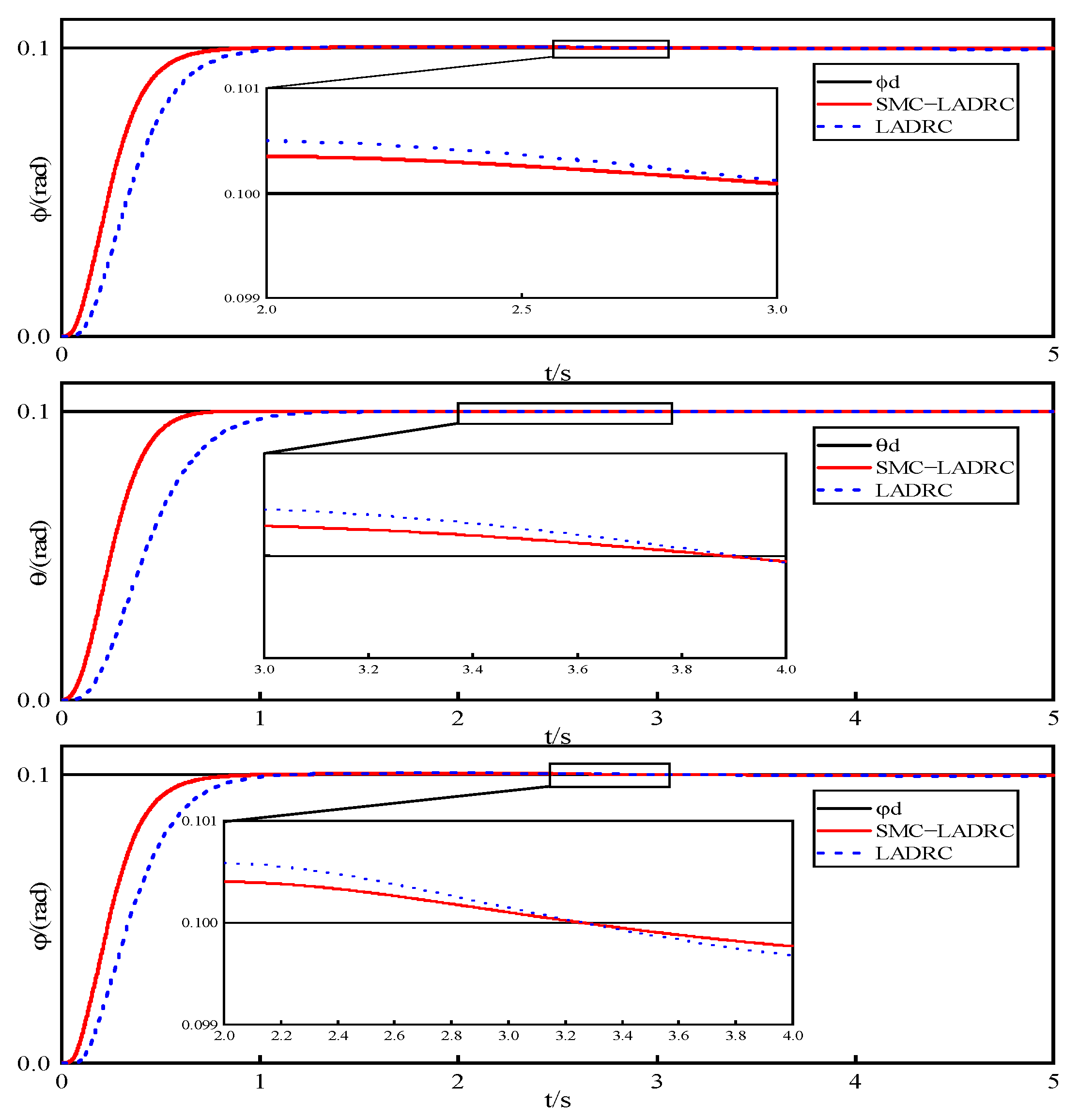
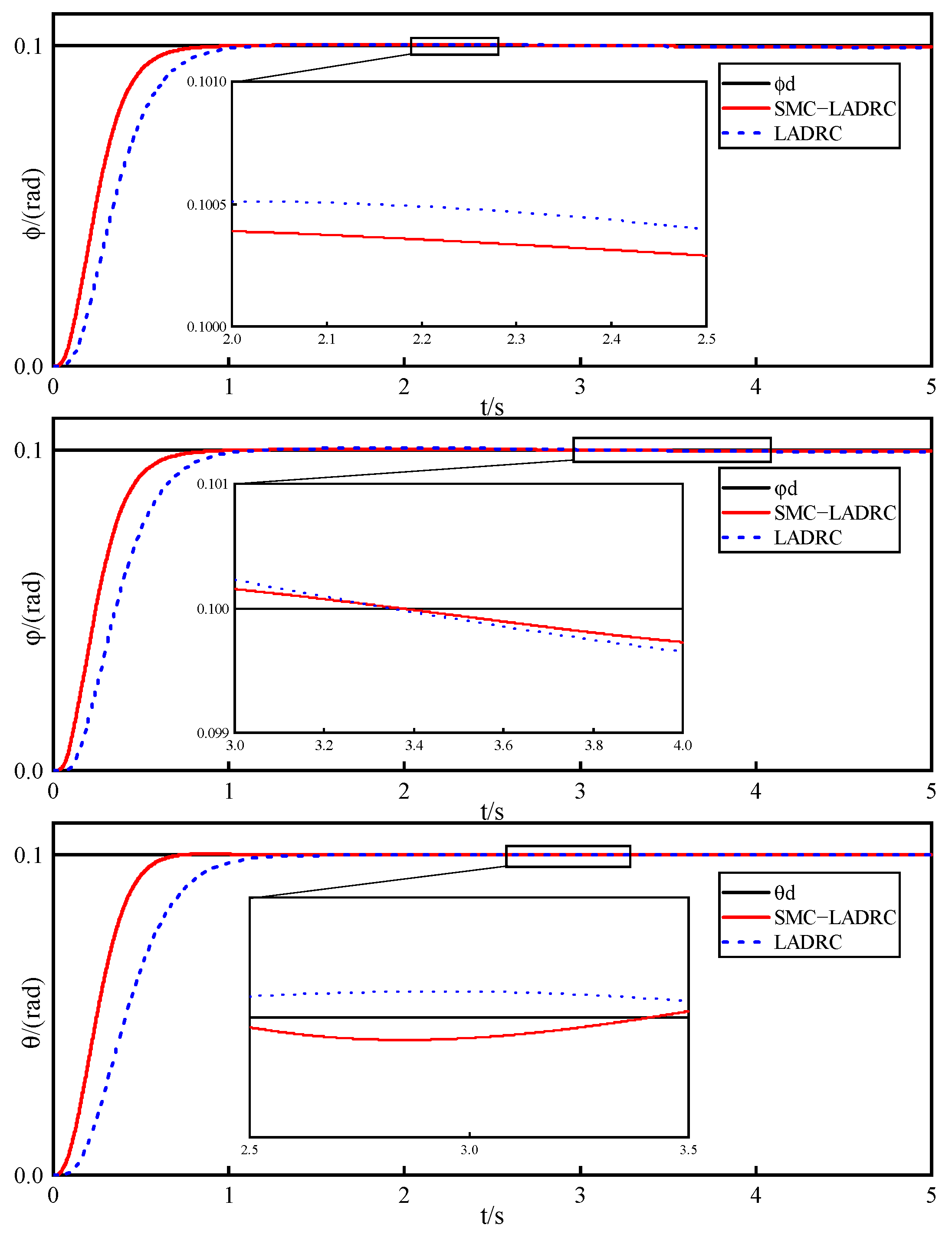
The main objective of this experiment is to investigate the attitude control of a fixed−wing UAV under wind disturbance. In the environment module of the fixed−wing UAV, a wind speed of 4 sin 0.2 π t   m / s units is applied along the x−axis and y−axis simultaneously. The desired inputs for the roll angle, pitch angle, and yaw angle are set to 0.1 radians, and the simulation results of SMC−LADRC and LADRC are compared. Figure 5 illustrates the comparison of attitude response curves. In the figure, the black curve represents the desired input, the red curve represents the SMC−LADRC control scheme, and the blue curve represents the LADRC control scheme. From Figure 5, it is evident that the proposed SMC−LADRC control scheme exhibits superior responsiveness compared to the LADRC control scheme.
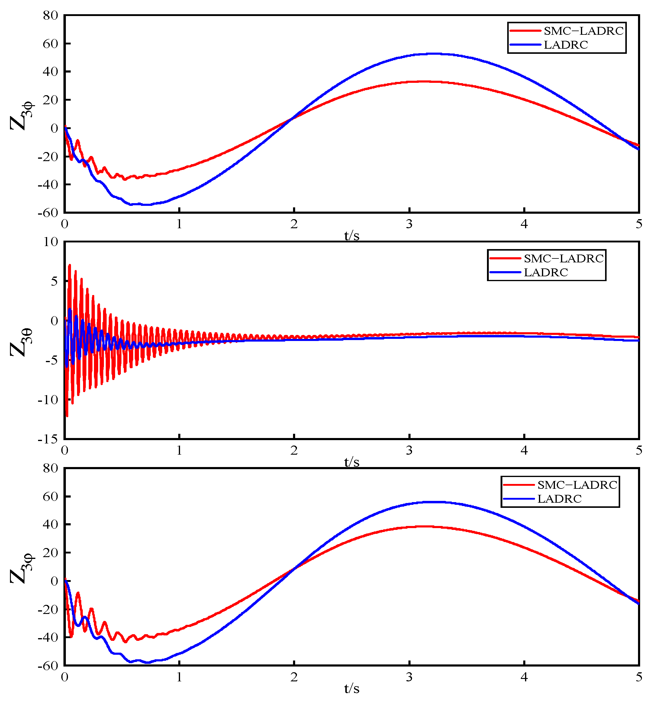
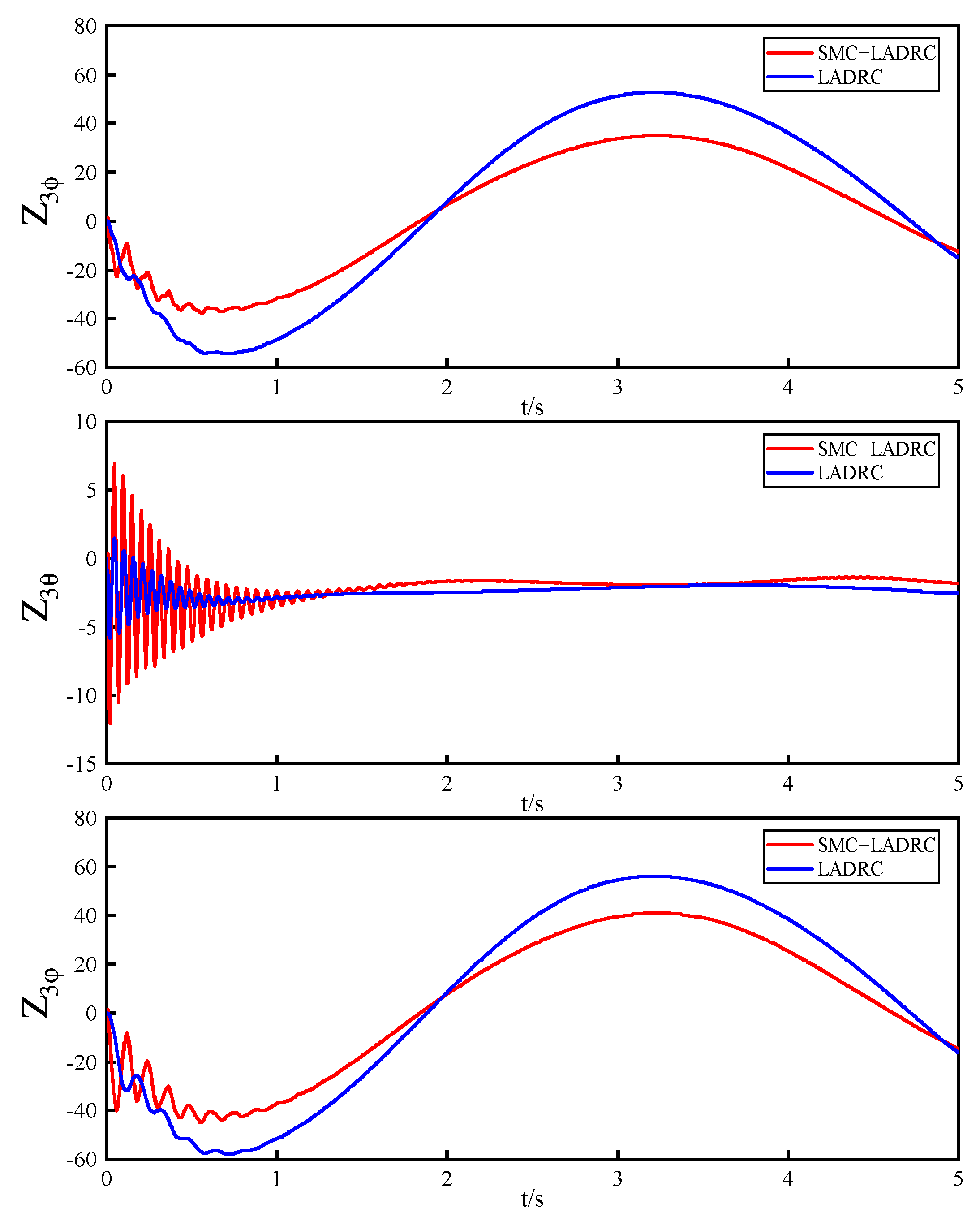
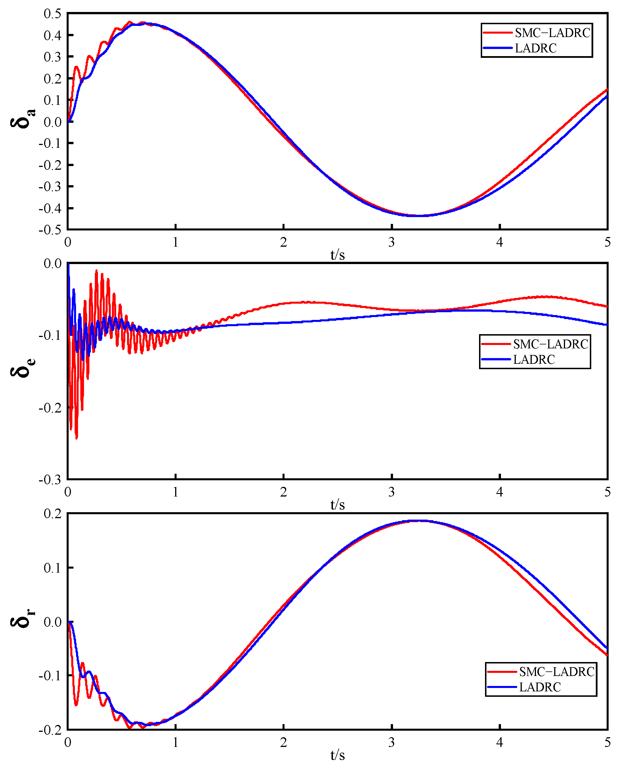
Figure 6 illustrates the total disturbance estimated by LESO under wind conditions, while Figure 7 depicts the controller’s output in the presence of wind disturbance. As shown in the figures, both the LESO estimation error and the controller output initially exhibit greater jitteriness for the SMC−LADRC control scheme compared to the LADRC control scheme at the start of the simulation. This is attributed to the robustness of sliding mode control, which trades off high−frequency oscillations that can limit its practicality. LESO mitigates these oscillations by treating the high−frequency oscillations induced by sliding mode control convergence as part of the disturbance. This explains the significant estimation errors and pronounced oscillations at the beginning of the simulation in the SMC−LADRC control scheme. In Figure 6, the northeast wind disturbance has a lesser impact on the pitch channel due to LESO being in the SMC−LADRC control scheme. Over time, the roll and yaw channels also show reduced disturbance estimates by LESO in the SMC−LADRC control scheme. This indicates that the SMC−LADRC control scheme effectively reduces the impact of wind disturbances on the UAV and exhibits enhanced anti−interference capabilities compared to the LADRC control scheme.
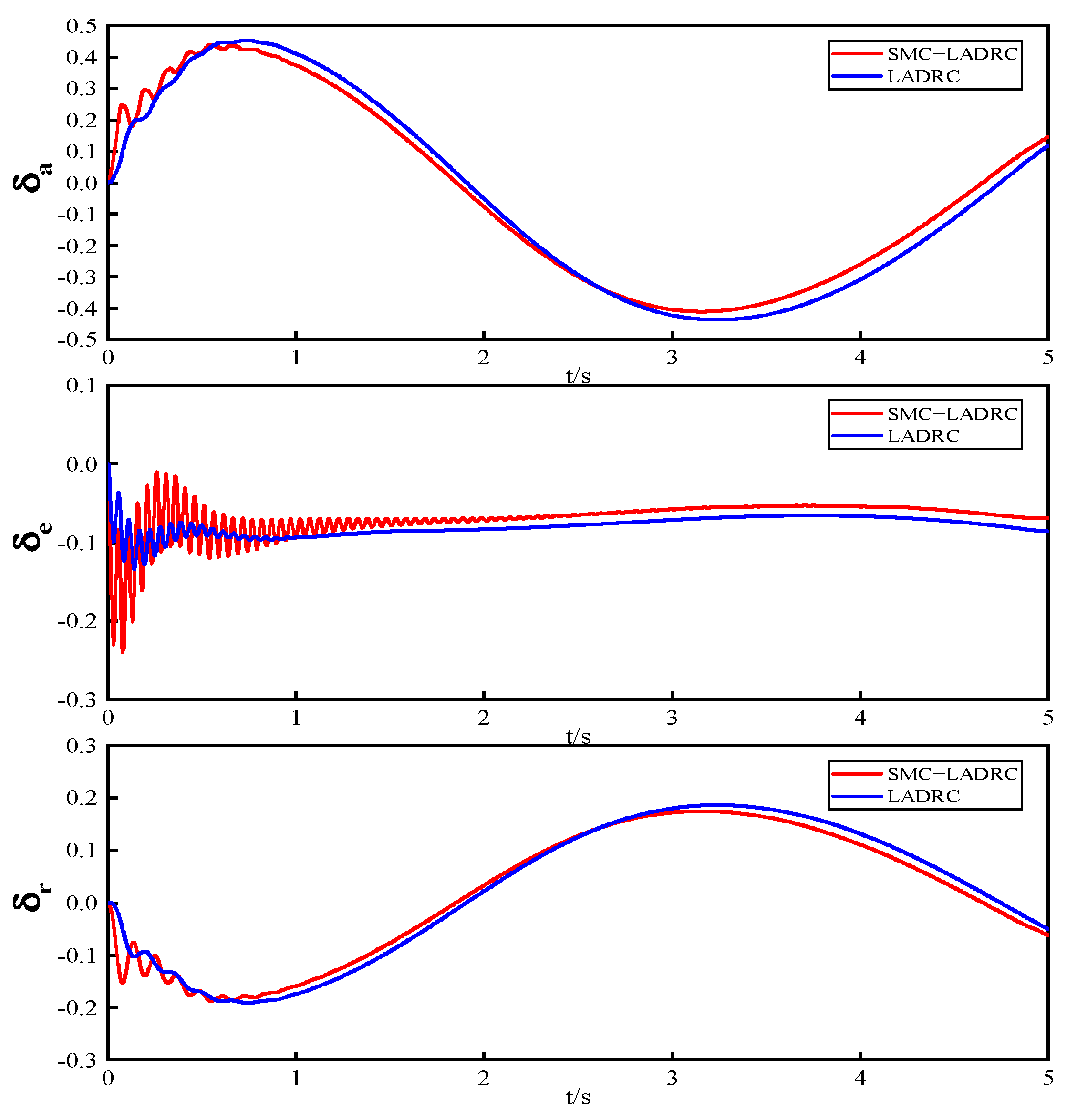
Initially, the output jitter of the SMC−LADRC control scheme is observed to be larger in the first second of simulation; however, this diminishes gradually as the simulation time increases. Moreover, the SMC−LADRC control scheme is found to yield a smaller output compared to the LADRC control scheme, suggesting reduced energy consumption by the UAV. Eventually, when both control schemes achieve the desired tracking input, their outputs are identical.

4.2. Experiments on the Effect of Sensor Noise on the System

In this experiment, sensor noise is assumed to follow a normal distribution with N(0,0.01) and is introduced into the system as a disturbance, as detailed in Section 4.1. Figure 8 depicts the attitude response curve influenced by the sensor, Figure 9 shows the total disturbance estimated by LESO under sensor influence, and Figure 10 displays the controller output affected by sensor noise. Figure 8 demonstrates that both control methods maintain the stable tracking of the desired input despite sensor disturbances. The SMC−LADRC control scheme shows less attitude fluctuation compared to the LADRC control scheme.
Figure 9 and Figure 10 indicate that the total disturbance estimate and controller output of the SMC−LADRC control scheme exhibit higher jitter frequencies than those of the LADRC control scheme during the initial 0–1 s response period. This behavior can be attributed to the SMC−LADRC controller’s emphasis on rapid response, which may lead to initial oscillations as the system reacts. Upon achieving the desired input, however, both the total disturbance estimates and the amplitude of the controller output for the SMC−LADRC control scheme are lower than those of the LADRC scheme. The experimental results demonstrate that integrating SMC effectively enhances the system’s anti−interference capabilities and reduces energy consumption.

4.3. Experiments on the Effect of Changes in Mass and Moment of Inertia on Systems

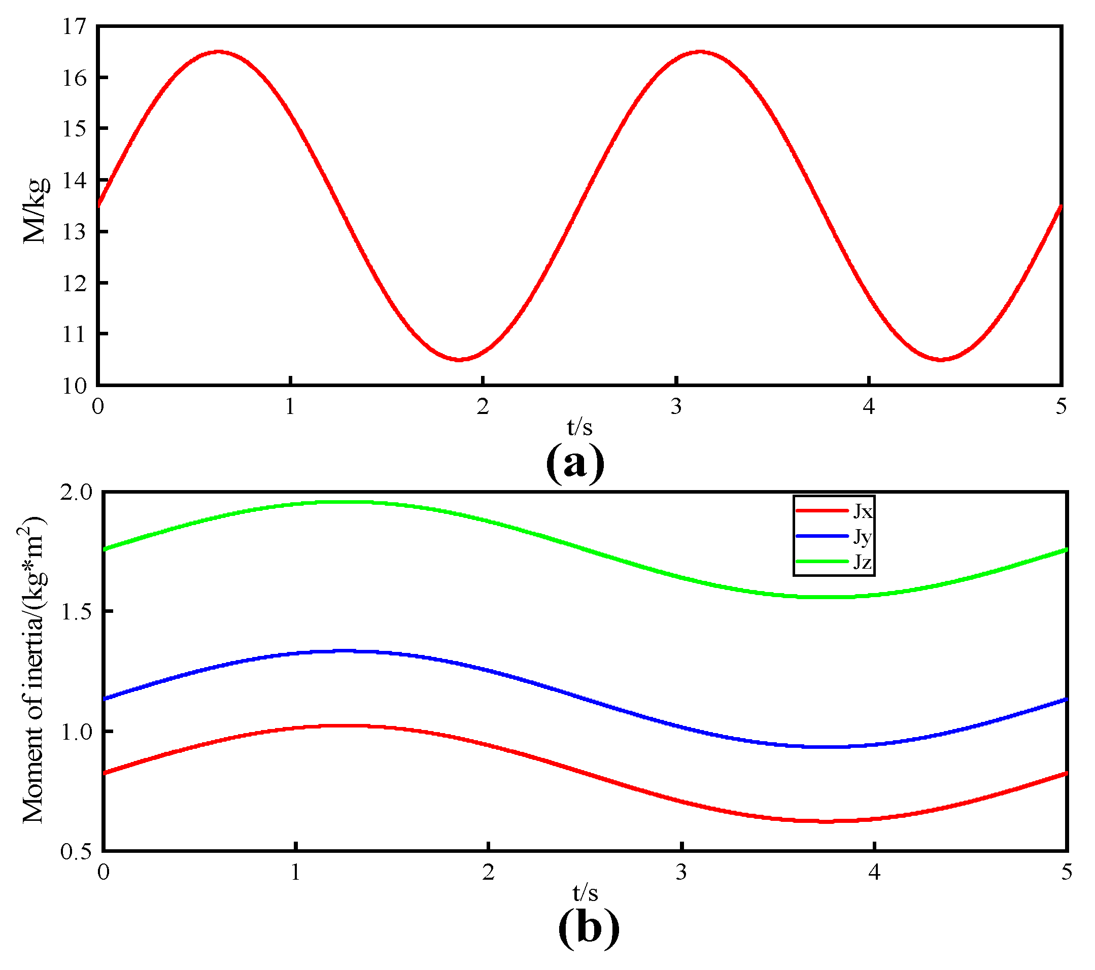
To demonstrate the system’s robustness to model parameter uncertainties, the results of the two control schemes are compared based on the experiments in Section 4.1, using perturbations such as changes in the mass and moment of inertia. The system’s model uncertainty includes variations in Δ m = 3 sin 0.4 π t and Δ J x = Δ J y = Δ J z = 0.2 sin 0.2 π t . Figure 11 illustrates the curves depicting the variations in model uncertainty.
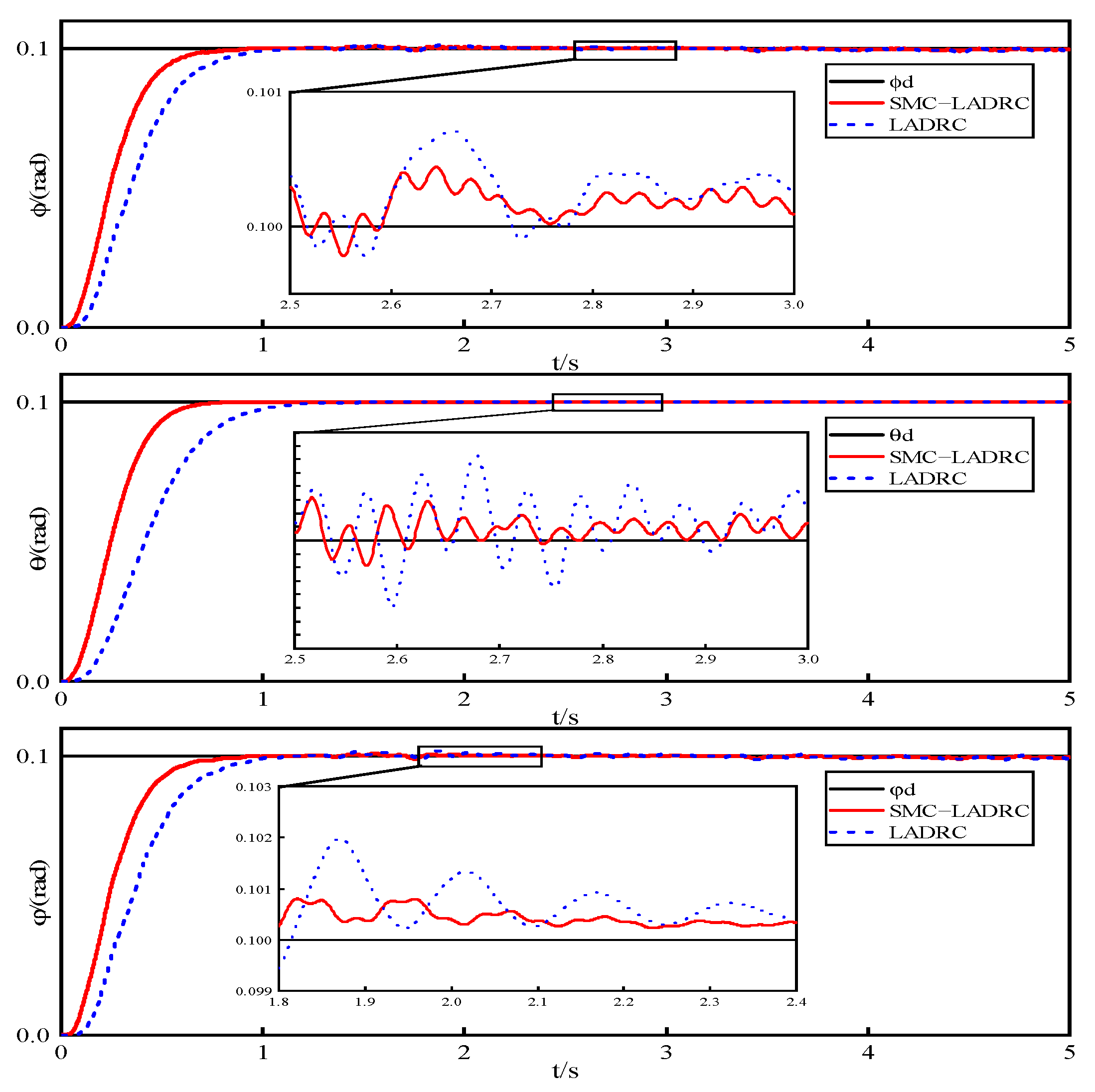
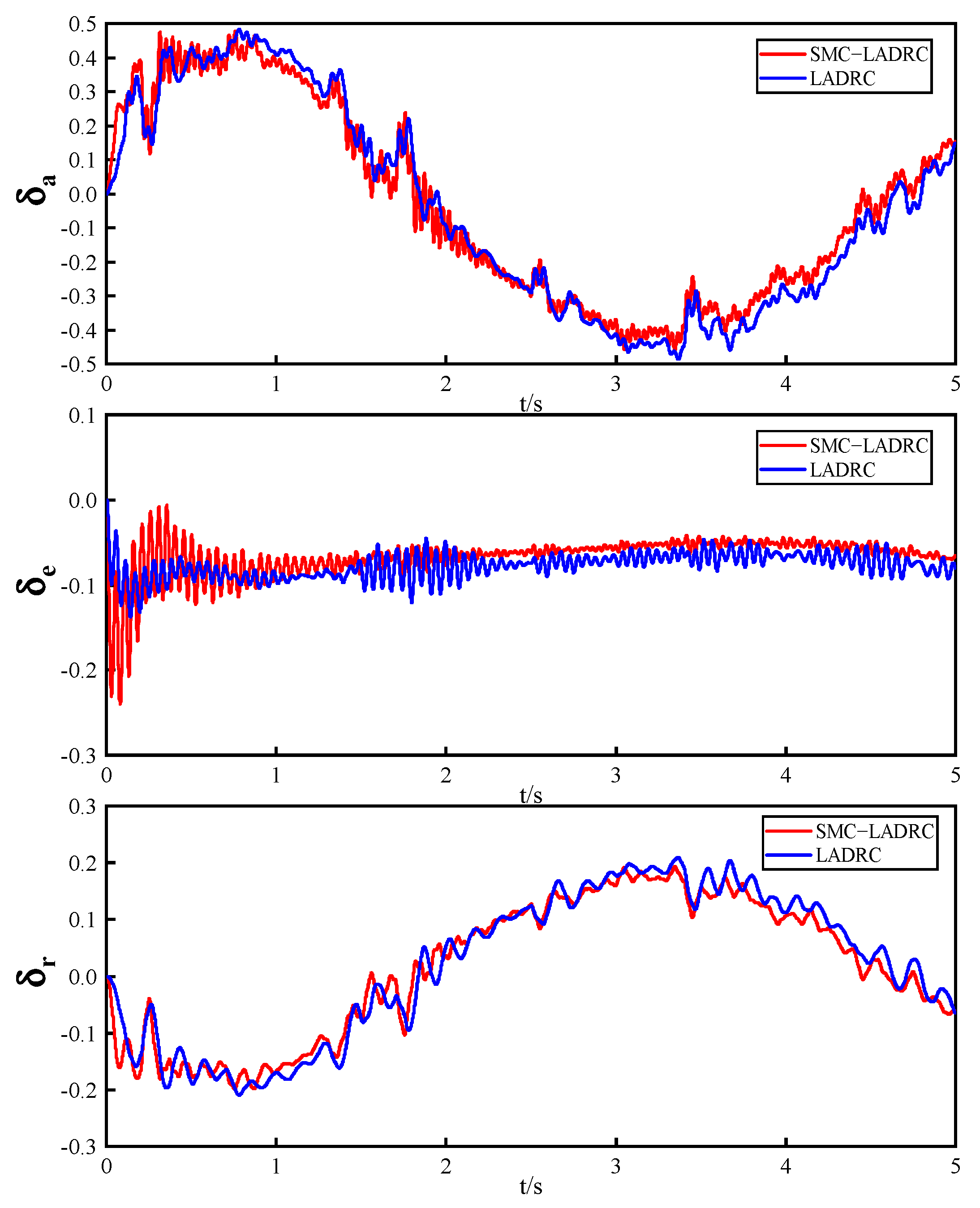
Figure 12 illustrates the attitude response curve under model uncertainty. Figure 13 depicts the total disturbance estimated by LESO under model uncertainty, while Figure 14 displays the controller output under model uncertainty. It can be observed from the figures that both methods effectively mitigate the impact of mass change and rotational inertia change on the attitude. Furthermore, the SMC−LADRC control scheme exhibits a faster response. Prior to the system reaching the desired input within the first second, the total disturbance estimated by LESO and the controller output shows larger and more erratic behavior for the SMC−LADRC, which is characteristic of its faster response. However, once the system has tracked the desired input, the total disturbance estimated by LESO and the controller output of the SMC−LADRC are smaller than those of the LADRC. The experimental results demonstrate that the SMC−LADRC control scheme more effectively mitigates the impact of model uncertainty on the system and exhibits enhanced robustness.

5. Conclusions

In this paper, a combined control method known as SMC−LADRC is introduced. This method provides an effective solution for mitigating the effects of external disturbances and model uncertainties on attitude control in UAV systems. The key conclusions drawn from this study are as follows:
  • LESO in LADRC is designed to estimate external disturbances and model uncertainties, providing estimated values for the attitude angle, attitude angular velocity, and total disturbance of the fixed−wing UAV. These estimates are used to compensate for system disturbances within the controller.
  • By replacing the error feedback law in LADRC with SMC, the insensitivity of SMC to system parameter variations is leveraged to enhance the anti−interference capabilities of the control system and improve the response speed.
  • The Trace Differentiator (TD) is introduced to track the desired inputs, aiming to minimize overshoot and enhance controller robustness. Incorporating TD helps the system achieve more stable tracking of the desired inputs, thereby enhancing the overall performance.
  • The experimental results demonstrate that compared to LADRC, SMC−LADRC exhibits faster response speeds and effectively suppresses model uncertainties, external disturbances, and internal disturbances impacting the UAV.
  • The controller proposed in this paper is based on LADRC and lacks experimental comparisons with other mainstream control methods. Moreover, it is solely applied to the attitude control of fixed−wing UAVs. To address these limitations, our future research will apply the SMC−LADRC controller to the position control of fixed−wing UAVs and include comparative experiments with other control methods.

Author Contributions

Conceptualization, methodology, software, validation, writing—original draft preparation, writing—review and editing, B.W.; funding acquisition, methodology, validation, resources, writing—review and editing, supervision, Y.Y.; methodology, validation, resources, writing—review and editing, supervision, X.X.; data curation, methodology, supervision, writing—review and editing, Q.H.; investigation, methodology, validation, Z.L. All authors have read and agreed to the published version of the manuscript.

Funding

This work was supported in part by the Innovation Fund of Chinese Universities under grant 2021ZYA09002.

Data Availability Statement

No new data were created or analyzed in this study. Data sharing is not applicable to this article.

Conflicts of Interest

The authors declare no conflicts of interest.

References

  1. Zhang, A.; Xu, H.; Bi, W.; Xu, S. Adaptive mutant particle swarm optimization based precise cargo airdrop of unmanned aerial vehicles. Appl. Soft Comput. 2022, 130, 109657. [Google Scholar] [CrossRef]
  2. Chamuah, A.; Singh, R. Responsible governance of civilian unmanned aerial vehicle (UAV) innovations for Indian crop insurance applications. J. Responsible Technol. 2022, 9, 100025. [Google Scholar] [CrossRef]
  3. Yang, Z.; Yu, X.; Dedman, S.; Rosso, M.; Zhu, J.; Yang, J.; Xia, Y.; Tian, Y.; Zhang, G.; Wang, J. UAV remote sensing applications in marine monitoring: Knowledge visualization and review. Sci. Total Environ. 2022, 838, 155939. [Google Scholar] [CrossRef] [PubMed]
  4. Hu, J.; Niu, H.; Carrasco, J.; Lennox, B.; Arvin, F. Fault−tolerant cooperative navigation of networked UAV swarms for forest fire monitoring. Aerosp. Sci. Technol. 2022, 123, 107494. [Google Scholar] [CrossRef]
  5. Valente, J.; Hiremath, S.; Ariza−Sentís, M.; Doldersum, M.; Kooistra, L. Mapping of Rumex obtusifolius in nature conservation areas using very high resolution UAV imagery and deep learning. Int. J. Appl. Earth Obs. Geoinf. 2022, 112, 102864. [Google Scholar] [CrossRef]
  6. Sun, M.; Zhang, L.; Wang, Z.; Chen, Z. PID pitch attitude control for unstable flight vehicle in the presence of actuator delay: Tuning and analysis. J. Frankl. Inst. 2014, 351, 5523–5547. [Google Scholar] [CrossRef]
  7. Anjali, B.; Vivek, A.; Nandagopal, J. Simulation and analysis of integral LQR controller for inner control loop design of a fixed wing micro aerial vehicle (MAV). Procedia Technol. 2016, 25, 76–83. [Google Scholar] [CrossRef]
  8. Matthew, J.S.; Knoebel, N.B.; Osborne, S.R.; Beard, R.W.; Eldredge, A. Adaptive backstepping control for miniature air vehicles. In Proceedings of the 2006 American Control Conference, Minneapolis, MN, USA, 14–16 June 2006; p. 6. [Google Scholar]
  9. Islam, S.; Liu, P.; El Saddik, A. Nonlinear adaptive control for quadrotor flying vehicle. Nonlinear Dyn. 2014, 78, 117–133. [Google Scholar] [CrossRef]
  10. Raffo, G.V.; Ortega, M.G.; Rubio, F.R. An integral predictive/nonlinear H∞ control structure for a quadrotor helicopter. Automatica 2010, 46, 29–39. [Google Scholar] [CrossRef]
  11. Shtessel, Y.; Edwards, C.; Fridman, L.; Levant, A. Sliding Mode Control and Observation; Springer: Berlin/Heidelberg, Germany, 2014; Volume 10. [Google Scholar]
  12. Han, J. From PID to active disturbance rejection control. IEEE Trans. Ind. Electron. 2009, 56, 900–906. [Google Scholar] [CrossRef]
  13. Gao, Z. Scaling and bandwidth−parameterization based controller tuning. In Proceedings of the 2003 American Control Conference, Denver, CO, USA, 4–6 June 2003; pp. 4989–4996. [Google Scholar]
  14. Pan, Y.; Li, N.; Zou, W.; Wang, B.; Wang, K.; Tang, X.; Bu, S.; Qin, L. An Augmented Sliding Mode Control for Fixed−Wing UAVs with External Disturbances and Model Uncertainties. Drones 2023, 7, 440. [Google Scholar] [CrossRef]
  15. Song, J.; Hu, Y.; Su, J.; Zhao, M.; Ai, S. Fractional−order linear active disturbance rejection control design and optimization based improved sparrow search algorithm for quadrotor uav with system uncertainties and external disturbance. Drones 2022, 6, 229. [Google Scholar] [CrossRef]
  16. Zheng, J.; Neusypin, K.A.; Selezneva, M.S. Auto−Landing of Moving−Mass Actuated Unmanned Aerial Vehicles Based on Linear Active Disturbance Rejection Control. Drones 2023, 7, 539. [Google Scholar] [CrossRef]
  17. Sun, C.; Liu, M.; Liu, C.a.; Feng, X.; Wu, H. An industrial quadrotor uav control method based on fuzzy adaptive linear active disturbance rejection control. Electronics 2021, 10, 376. [Google Scholar] [CrossRef]
  18. Suhail, S.A.; Bazaz, M.A.; Hussain, S. Adaptive sliding mode−based active disturbance rejection control for a quadcopter. Trans. Inst. Meas. Control 2022, 44, 3176–3190. [Google Scholar] [CrossRef]
  19. Zheng, J.; Selezneva, M.S.; Yi, J.; Zhu, L. Attitude control of a moving mass−actuated fixed−wing UAV based on LADRC. Proc. J. Phys. Conf. Ser. 2023, 2472, 012045. [Google Scholar] [CrossRef]
  20. Kikkawa, H.; Uchiyama, K. Nonlinear flight control with an extended state observer for a fixed−wing UAV. In Proceedings of the 2017 International Conference on Unmanned Aircraft Systems (ICUAS), Miami, FL, USA, 13–16 June 2017; pp. 1625–1630. [Google Scholar]
  21. Xu, L.; Ma, H.; Guo, D.; Xie, A.; Song, D. Backstepping Sliding−Mode and Cascade Active Disturbance Rejection Control for a Quadrotor UAV. IEEE/ASME Trans. Mechatron. 2020, 25, 2743–2753. [Google Scholar] [CrossRef]
  22. Wang, Z.; Zhao, T. Based on robust sliding mode and linear active disturbance rejection control for attitude of quadrotor load UAV. Nonlinear Dyn. 2022, 108, 3485–3503. [Google Scholar] [CrossRef]
  23. Beard, R.W.; McLain, T.W. Small Unmanned Aircraft: Theory and Practice; Princeton University Press: Princeton, NJ, USA, 2012. [Google Scholar]
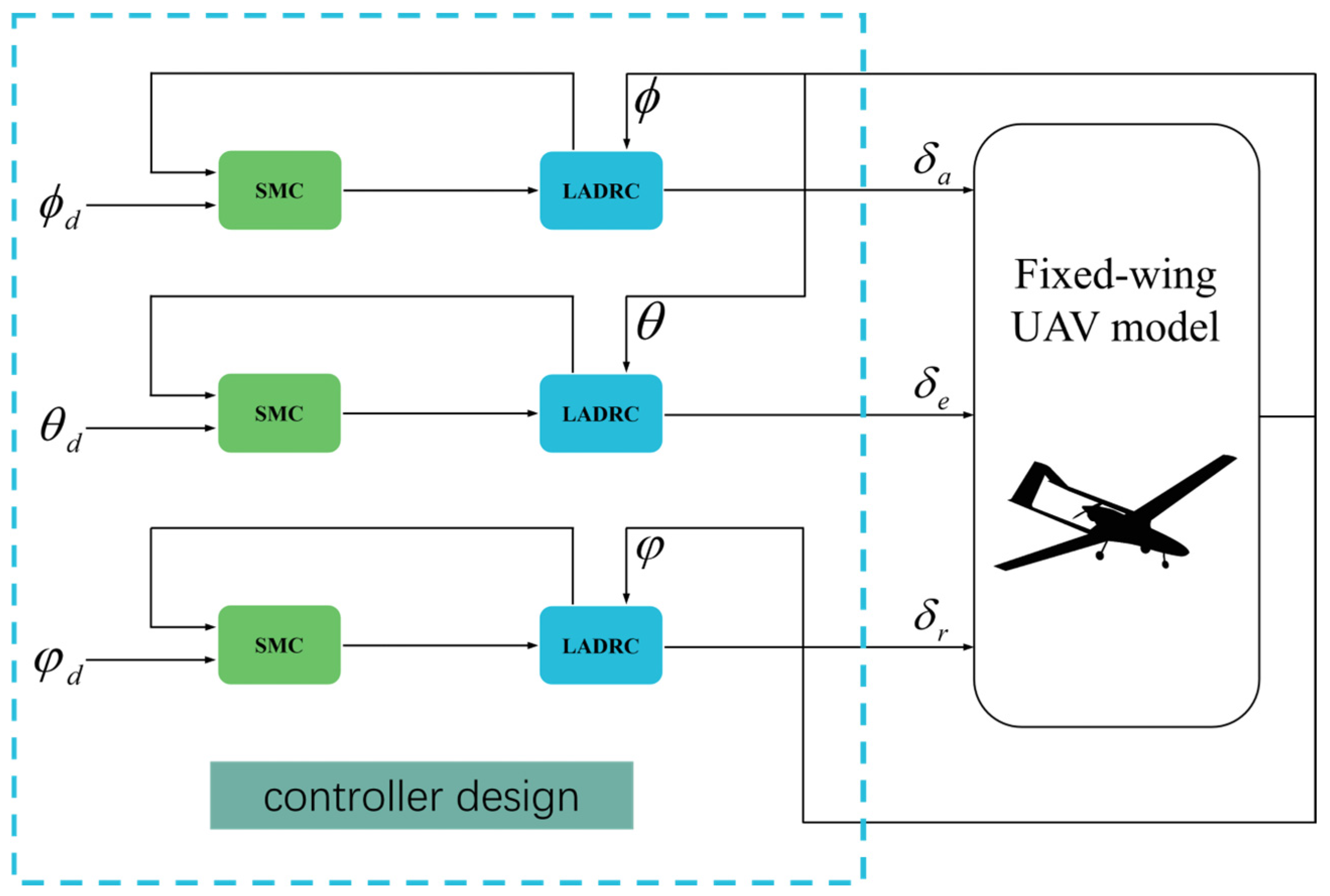
Figure 1. The structure of this paper.
Drones 08 00318 g001
Figure 2. The UAV coordinate system.
Drones 08 00318 g002
Figure 3. Controller block diagram for LADRC.
Drones 08 00318 g003
Figure 4. Controller block diagram for SMC−LADRC.
Drones 08 00318 g004
Figure 5. Response curve comparison of attitude angle under wind disturbance.
Drones 08 00318 g005
Figure 6. LESO estimates of the total disturbance in the presence of wind disturbance.
Drones 08 00318 g006
Figure 7. The output of the controller under wind disturbance.
Drones 08 00318 g007
Figure 8. Attitude response curve under the influence of sensor noise.
Drones 08 00318 g008
Figure 9. LESO Estimated Total Disturbance under the Influence of Sensor Noise.
Drones 08 00318 g009
Figure 10. Controller output under the influence of sensor noise.
Drones 08 00318 g010
Figure 11. Model uncertainty variation curves: (a) mass; (b) moment of inertia.
Drones 08 00318 g011
Figure 12. Attitude response curve under model uncertainty.
Drones 08 00318 g012
Figure 13. The total disturbance value estimated by LESO under model uncertainty.
Drones 08 00318 g013
Figure 14. The controller output under model uncertainty.
Drones 08 00318 g014
Table 1. Parameters of fixed−wing UAV.
ParameterValueParameterValue
m 13.5   kg C Y 0 0
J x 0.8244   kg · m 2 C Y β −0.9
J y 1.135   kg · m 2 C Y p −0.49497
J z 1.759   kg · m 2 C Y r 0.3971
J x z 0.1204   kg · m 2 C Y δ a 0.1
S 0.55   m 2 C Y δ r −0.15
b m C l 0 0
c m C l β −0.12
S p r o p 0.2027   m 2 C l p −0.26
ρ 1.2682   kg / m 3 C l r 0.14
k m o t o r 80 C l δ a 0.08
C p r o p 1 C l δ r 0.105
C L 0 0.21 C m 0 0
C L α 0 C m α −1
C L q 0 C m q −3.6
C L δ e −0.36 C m δ e −0.58
C D 0 0.0164 C n 0 0
C D α 0.2 C n β 0.25
C D q 0 C n p 0.022
C D δ e 0 C n r −0.35
C n δ a 0.06 C n δ r −0.032
Table 2. Parameters of SMC−LADRC.
Parameter ϕ θ φ
r 888
h 0.0010.0010.001
b 80−30−240
ω 160016221600
c 141314
k 161116
ε 0.0010.0010.001
Disclaimer/Publisher’s Note: The statements, opinions and data contained in all publications are solely those of the individual author(s) and contributor(s) and not of MDPI and/or the editor(s). MDPI and/or the editor(s) disclaim responsibility for any injury to people or property resulting from any ideas, methods, instructions or products referred to in the content.