Article

Real-Time Registration of Unmanned Aerial Vehicle Hyperspectral Remote Sensing Images Using an Acousto-Optic Tunable Filter Spectrometer

1
Xi’an Institute of Optics and Precision Mechanics, Chinese Academy of Sciences, Xi’an 710119, China
2
School of Electronic and Information Engineering, Xi’an Jiao Tong University, Xi’an 710049, China
3
Key Laboratory of Spectral Imaging Technology, Chinese Academy of Sciences, Xi’an 710119, China
4
University of Chinese Academy of Sciences, Beijing 100049, China
*
Author to whom correspondence should be addressed.
Drones 2024, 8(7), 329; https://doi.org/10.3390/drones8070329
Submission received: 22 April 2024 / Revised: 13 July 2024 / Accepted: 14 July 2024 / Published: 17 July 2024

Abstract

:
Differences in field of view may occur during unmanned aerial remote sensing imaging applications with acousto-optic tunable filter (AOTF) spectral imagers using zoom lenses. These differences may stem from image size deformation caused by the zoom lens, image drift caused by AOTF wavelength switching, and drone platform jitter. However, they can be addressed using hyperspectral image registration. This article proposes a new coarse-to-fine remote sensing image registration framework based on feature and optical flow theory, comparing its performance with that of existing registration algorithms using the same dataset. The proposed method increases the structure similarity index by 5.2 times, reduces the root mean square error by 3.1 times, and increases the mutual information by 1.9 times. To meet the real-time processing requirements of the AOTF spectrometer in remote sensing, a development environment using VS2023+CUDA+OPENCV was established to improve the demons registration algorithm. The registration algorithm for the central processing unit+graphics processing unit (CPU+GPU) achieved an acceleration ratio of ~30 times compared to that of a CPU alone. Finally, the real-time registration effect of spectral data during flight was verified. The proposed method demonstrates that AOTF hyperspectral imagers can be used in real-time remote sensing applications on unmanned aerial vehicles.

1. Introduction

Image registration technology refers to the process of geometric alignment of two images acquired at different times, from different perspectives, and from different sensors [1,2]. Image registration in the field of remote sensing is an essential part of many remote sensing image processes, such as object detection, urban development assessment, geographic change assessment, hyperspectral image stitching, precision agriculture, and biomedical applications [3,4,5,6,7,8]. These tasks need to be carried out to achieve successful registration; thus, further research on remote sensing image registration is deemed necessary and crucial.
Acousto-optic tunable filter (AOTF) spectral imagers are frame scanning-based imagers with an adjustable number of spectral channels, and they capture the entire data cube by sequentially exposing each band. However, in remote sensing flight experiments, changes in sensor position and attitude are caused by airflow disturbances and drone vibrations, resulting in spatial positional deviations in different spectral bands. Different spectral bands cannot be fully matched in the original data cube, leading to spectral registration errors. Therefore, it is necessary to implement post-processing registration correction.
AOTFs present advantages that include small size, light weight, no moving parts, flexible wavelength selection, and strong environmental adaptability [9], thus making them suitable as spectroscopic devices for high-resolution imaging spectrometers in aerial remote sensing [10,11]. However, in remote sensing imaging based on AOTF hyperspectral instruments, it is imperative to address any issues that may arise in the collected data.
Sharikova et al. [12] studied the spatial spectral distortion caused by acousto-optic diffraction and performed spatial and spectral calibration on imaging spectrometers based on AOTFs to develop a technique for balancing the transmittance of AOTFs throughout the entire working spectral range. To obtain undistorted data, spectral and spatial non-uniformity must be corrected. The calibration process included hardware spectral tuning of acousto-optic devices and mathematical corrections to software. The proposed method can perform real-time hardware calibration of hyperspectral devices based on AOTFs and software calibration of display results. This method is universal and suitable for other imaging spectrometers based on acousto-optic monochromaticization.
Zhang and Zhao [13] focused on the design and analysis of non-collinear AOTFs, and they used a refractive index correction to resolve the geometric parameter introduction error (0.5° or greater) that cannot be ignored in tellurium dioxide (TeO2) non-collinear AOTFs. This basic theoretical research is crucial for the design and application of non-collinear AOTFs.
Zhao et al. [14] studied the spectral and spatial characteristics of AOTFs, such as tuning curves, spectral resolution, angular aperture, and diffraction efficiency, determined by the device’s acousto-optic crystal configuration and piezoelectric transducers. For high-throughput spectral imaging applications, it is crucial to expand the spectral bandwidth and angular aperture during the design phase of AOTFs. Therefore, this article analyzes and studies the phase mismatch caused by incident angle or wavelength using phase diagrams. In addition, a performance parameter analysis model was established for the design of large angle aperture AOTF devices based on mercuric bromide crystals, and the effects of crystal and transducer design parameters on spectral bandwidth and angle aperture were evaluated.
Yu et al. [15] investigated spectral drift, which is a unique challenge when using an AOTF spectrometer to observe moving targets, and revealed that an online spectral calibration method based on acousto-optic interaction is required. A reverse ray tracking model was constructed using the imaging position and driving frequency of the target spectrum, and it achieved real-time calibration of spectral data and ensured the stability and accuracy of subsequent target detection, recognition, and tracking. Experimental verification was conducted using the developed parallel incident light mid-infrared AOTF spectral detection system. The results showed that for simulated moving targets with different fields of view, the correction accuracy of spectral drift was greater than 4.45%. This improvement enhanced the application capability of the spectral detection of moving targets.
In our previous research on the design of an electric zoom lens AOTF spectrometer, we addressed the issue of image blurring, which causes image size deformation due to zoom, image drift due to wavelength switching, and drone platform shaking in remote sensing applications [16]. The issue of cube registration based on AOTF spectrometer imaging data has not been previously studied. According to general image processing and remote sensing image processing methods, it is widely recognized that current methods of solving remote sensing spectral data image registration mainly include grayscale and template-based, feature-based, and domain transformation-based methods, as well as machine learning and artificial intelligence-based methods [17]. Therefore, the methods for addressing remote sensing spectral data image registration can be roughly divided into these four categories.
Grayscale and template-based methods directly use correlation operations and other approaches to calculate the correlation value to identify the best matching position. Blocking matching is performed to search for sub-images similar to the template image in another image based on a known template image. Li et al. [18] proposed a deep learning semantic template matching framework for remote sensing image registration. Driven by learning-based methods, reference images and template images are taken as inputs and mapped to the semantic distribution positions of the corresponding reference images. Ruiqi et al. [19] proposed a template-matching method based on a deep global feature-based template-matching method (GFTM) to achieve fast and accurate multimodal image registration. The method performs fast template matching on global deep features to search for positions with maximum similarity. A large number of experimental results on optical and synthetic aperture radar (SAR) images have shown that the proposed method is effective for multimodal image registration.
In feature-based methods, the features of the image are extracted, feature descriptors are generated, and the features of the two images are matched based on the similarity of the descriptors. The features of an image can mainly be divided into points, lines (edges), regions (faces), and other features, as well as local features and global features. The extraction of regional (surface) features is relatively cumbersome and time-consuming; therefore, point features and edge features are mainly used. Point features include the Harris, histogram of oriented gradient (HOG), local binary pattern (LBP), scale-invariant feature transform (SIFT), speeded up robust features (SURF), binary robust independent elementary features (BRIEF), smallest univalue segment assimilating nucleus (SUSAN), features from accelerated segment test (FAST), fast retina keypoint (FREAK), binary robust invariant scalable keypoints (BRISK), oriented FAST and rotated BRIEF (ORB) algorithms and classifiers [6,7,8]. Edge features include the LoG operator, Robert operator, Sobel operator, Prewitt operator, and Canny operator. Ye et al. [20] proposed a new keypoint feature detector aimed at the simultaneous extraction of corners and spots and the calculation of SIFT descriptors for detected corners and spots and applied them jointly for remote sensing image registration. Wu et al. [21] proposed a robust and accurate feature point-matching framework. An improved SIFT method was first proposed for feature detection and matching, and it was applied to automatic remote sensing image registration. Zhang et al. [22] proposed an improved algorithm for the SURF classic algorithm, which is a short time and high-precision image registration algorithm that can meet the registration requirements of remote sensing image stitching. Chen et al. [23] proposed an iterative image registration method for remote sensing images, known as iterative scale-invariant feature transform (ISIFT). This method extends the registration system based on SIFT to a closed-feedback SIFT system that includes a correction feedback loop, iteratively updating the correction parameters. The experimental results show that compared with traditional SIFT-based methods and state-of-the-art methods, ISIFT improves performance and yields better registration accuracy. Jhan et al. [24] proposed a normalized SURF (N-SURF), which can substantially increase the number of correct matches between different multispectral image pairs, enabling one-step image registration. Additionally, they developed an automatic multispectral image registration tool suitable for multi-lens multispectral cameras. Wu et al. [25] proposed a two-step remote sensing image registration method based on local and global constraints. Experiments on multiple remote sensing image datasets have shown that this method is more robust and accurate than existing methods.
Based on domain transformation, phase correlation (Fourier Merlin transform), Walsh transform, and wavelet transform are used for registration in new domains. Ordóñez et al. [26] proposed a phase correlation algorithm based on FFT and developed a graphics processing unit (GPU) to register two remote-sensing hyperspectral images. The proposed algorithm is based on multi-layer fractional Fourier transform and logarithmic polar plots. Liu et al. [27] proposed a multi-constraint registration algorithm based on variational inference for complex remote sensing image registration problems. The experimental results showed that compared with other point set matching algorithms, their method demonstrated strong performance in terms of robustness and matching accuracy. Zhou et al. [28] proposed a novel image registration algorithm using wavelet transform and matrix multiple discrete Fourier transform, and the results showed that it can perform sub-pixel registration via full image-based methods but with shorter computation times.
Regarding machine learning and artificial intelligence-based methods, Lee et al. [29] proposed a remote sensing registration framework based on convolutional neural networks to improve the registration accuracy between two remote sensing images obtained from different times and viewpoints. The proposed high-precision registration framework was evaluated using the KOMPSAT-3 dataset and obtained a minimum root mean square error value of 34.922 based on all control points and improved the matching accuracy by 68.4% compared to traditional registration frameworks. Zeng et al. [30] proposed an image registration method based on hierarchical convolutional features and applied it to improve the efficiency of large-scale forestry image stitching generation. This method uses a deep learning architecture to adaptively obtain image features from deep convolutional neural networks. The experimental results showed that this method can detect and match image feature points with marked spectral differences and effectively extract feature points to generate accurate image registration and stitching results. Ye et al. [31] proposed a multi-scale framework with unsupervised learning called MU Net. Without expensive ground truth labels, MU Net directly learns end-to-end mapping from image pairs to their transformation parameters. The experimental results indicated that MU Net achieved more comprehensive and accurate registration between image pairs with geometric and radiative distortions. Chen et al. [32] proposed a dense connected neural network (RBDCNN) that was improved by residual blocks to extract feature values, which improved registration performance and utilized the distance difference between the transformation matrices of reference images and floating images. Compared with existing methods, the registration results were closer to that of the reference image.
With the increasing demand for high accuracy in remote sensing image registration, the complexity of remote sensing image registration algorithms is also increasing, which has led to calculation times that are too long to be used in situations with high real-time requirements. Hyperspectral image registration is a real-time application-related task, such as environmental disaster management or search and rescue scenarios [33]. The compute unified device architecture (CUDA) has advantages such as low cost, low power consumption, good portability, and flexible code modification. Therefore, by combining the advantages of a GPU in general computing and the processing speed issues faced by remote sensing image registration, a fast remote sensing image registration algorithm based on CUDA parallel computing can be developed. Liu et al. [34] utilized swarm intelligence GPUs to accelerate SAR image registration in parallel and achieve fully parallelized registration. The experimental results showed that this method can achieve approximately 40-times higher acceleration. Ordóñez et al. [35] proposed the first method of implementing hyperspectral KAZE (HSI-KAZE) with multiple nodes and GPUs for jointly registering band and multispectral images. In this method, different multispectral datasets are distributed between available nodes in the cluster using MPI, and CUDA utilizes the parallel flow-based capabilities of the GPUs within each node. Subsequently, HSI-KAZE was used in cluster systems to achieve multi-GPU registration of high-resolution multispectral images. Zhang et al. [36] proposed a multi-frame image registration algorithm and its parallel design method for high-resolution images. Compared with feature point algorithms and deep learning algorithms, the proposed algorithm and its parallel design considerably improve the registration accuracy and speed of high-resolution optical remote sensing images.
To solve the issues of image size deformation, image drift, and image jitter in the unmanned aerial vehicle remote sensing spectral data cube collected using the AOTF spectrometer based on the electric zoom lens, we used image registration methods to solve these problems. Compared with the current methods for hyperspectral image registration, the predominant approaches include grayscale and template-based, feature-based, and domain transformation-based methods, as well as some machine learning and artificial intelligence methods. A coarse-to-fine remote sensing image registration method was proposed based on feature and optical flow theory. In the coarse registration stage, the feature-based registration method was used to solve the registration problem of scale transformation, rotation, and other overall transformations. In the fine registration stage, the image registration method (based on optical flow theory) was used to solve the registration problem of the local details in the image, such as issues with image zoom produced by the use of a zoom lens and differences in the field of view caused by small jitter movements. The main objectives of this study were as follows:
  • To propose a new coarse-to-fine remote sensing image registration framework based on feature and optical flow theory. The data cube composed of collected spectral segments registers the data of each spectral segment (registration between adjacent spectral segments) after resolving image blurring and spectral segment drift of the AOTF spectrometer using a fast zoom lens. The performance of the proposed method was compared with that of other advanced algorithms.
  • To construct a VS2023+CUDA+OPENCV development environment for the improved demons registration algorithm based on optical flow theory, which is highly suitable for distributed and parallel processing. Parallel processing using the compute unified device architecture (CUDA) was performed to achieve rapid registration and enable real-time processing.
  • To verify the proposed method based on the existing AOTF unmanned airborne spectrometer platform. The data cubes on each shooting waypoint were registered online and met the requirements of real-time registration on unmanned aerial vehicles (UAVs) and real-time processing on aircraft.

2. Related Work

This section provides information about the proposed method. First, the airborne AOTF spectrometer based on a zoom lens is introduced. Then, the image registration algorithm based on the optical flow theory is described, constituting the main part of the fine registration. Finally, the image processing algorithm acceleration based on GPU use is introduced.

2.1. Airborne AOTF Spectrometer for UAVs Based on the Zoom Lens

With the rapid development of material technology and the increasing maturity of optical device manufacturing technology, optical splitters have transformed from traditional prisms, gratings, etc., to new devices with higher spectral resolution, miniaturization, integration, and intelligence [37]. AOTF represents an all-solid-state filtering and polarization modulation device that can achieve fast electronic control tuning without mechanical moving components. This technology has many advantages, such as compact structure, high diffraction efficiency, and wide tuning range. Moreover, it has been applied in the development process of spectral imaging systems [38,39].
The airborne imaging system consists of an AOTF imaging spectrometer based on an electric zoom lens, an AOTF driver, a MINI-PC with GPU, and a battery. The composition diagram of the unmanned aerial vehicle hyperspectral imaging system based on AOTF is shown in Figure 1.
The core optical path structure of the AOTF spectrometer based on an electric zoom lens is shown in Figure 2.
In Figure 2, the core optical path structure of the AOTF spectrometer is presented, illustrating (1) electrically controlled zoom lens; (2) front objective lens; (3) aperture diagram; (4) collimating lens; (5) linear polarizer; (6) AOTF, composed of tellurium dioxide (TeO2) crystals and piezoelectric transducers; (7) linear polarizer; (8) secondary imaging lens; (9) CMOS detector; (10) MINI-PC control and data acquisition system; and (11) RF driver.
The incident beam is refracted by an electrically controlled variable angle lens (1), a front objective lens (2), aperture diagram (3), and a collimating lens before being vertically incident on the surface of a linear polarizer (4). After polarization, the beam is vertically incident on the surface of the AOTF module. The incident light and ultrasound interact with each other inside the AOTF module to produce a diffracted beam. After passing through the linear polarizer (6), the beam is focused by a secondary imaging lens (8) on the imaging surface of the CMOS detector. Subsequently, the collected data are processed by the MINI-PC. Specifically, the polarization direction of the linear polarizer (5) is parallel to the acoustic optical interaction plane of the AOTF and perpendicular to the polarization direction of the linear polarizer (7). The purpose of using a polarizer (7) is to filter out the 0-level transmitted light.
The design materials for the AOTF spectrometer prototype based on an electric zoom lens are shown in Table 1.

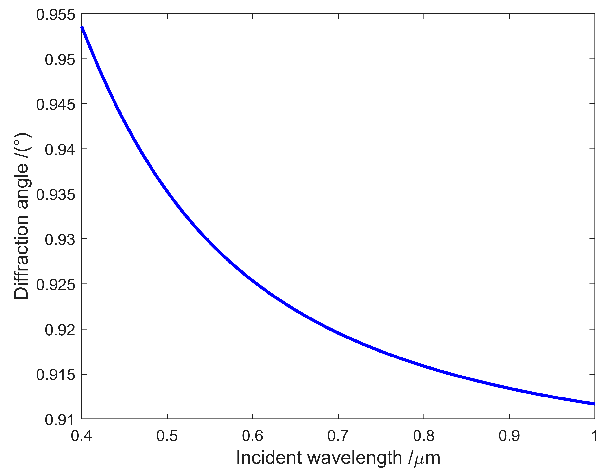
2.2. AOTF Spectral Characteristics

The main material of the AOTF crystal is TeO2. Due to the characteristics of Bragg diffraction in TeO2 crystals, the light passing through the crystal has different deflection angles for different wavelengths of diffracted light, resulting in angular displacement errors [40]. Previous studies have demonstrated the relationship between the diffraction angle and wavelength of AOTF crystals [41,42], which is described below.
The geometric relationship is satisfied by the incident light angle θ i , diffracted light angle θ d , and external diffraction angle β is defined as follows:
sin β = sin θ i θ d
where n d is the refractive index of TeO2 crystals corresponding to the wavelength of the diffracted light. In addition, n d = n o , where n o is the refractive index of o light when the optical rotation of the crystal is not considered. The order angle of the diffracted light can be written as follows:
tan θ d = n o n e 2 tan θ i
Equation (2) is a function of incident light wavelength. The geometric relationship is satisfied in (3) when the emitting end face of the TeO2 crystal is not parallel to the incident end face:
sin β = n d sin θ i θ d θ ω
where θ ω is the increased wedge angle of the exit end face of the crystal. Generally, the relationship between the refractive index and wavelength is shown below:
n o 2 = 1 + 2.5488 λ 2 λ 2 0.1342 2 + 1.1557 λ 2 λ 2 0.2638 2
n e 2 = 1 + 2.8525 λ 2 λ 2 0.1342 2 + 1.5141 λ 2 λ 2 0.2631 2
where n e is the refractive index of e-light, and both n o and n e are functions of the wavelength of light λ . Based on the above equations, the expression of the external diffraction angle of the e-light crystal can be obtained as follows:
β = a r c s i n 1 + 2.5488 λ 2 λ 2 0.1342 2 + 1.1557 λ 2 λ 2 0.2638 2 1 2 * sin θ i θ d θ ω
In this equation, the following assumptions were made: the incident light is the e-light, the incident angle θ i 22.7 ° , and the wedge angle of the crystal exit end face θ ω 0.6 ° . The varying relationship between the diffraction angle β and incident light wavelength is shown in Figure 2. Based on the figure, β changes to 0.0419° over the whole wavelength range. The translation of the central image plane is approximately f × tan 0.0419 ° 11.7   μ m if the focal length f = 16   m m . We can infer that the change in the diffraction angle with respect to the wavelength over the whole wavelength range affects the imaging quality of the AOTF spectrometer.
From Figure 3, it can be seen that when the angle displacement error is small (in a small spectral range, such as 500–550 nm), the image captured on the detector focal plane will experience spectral drift. When the angle displacement error is large (wide spectral range, such as 500–900 nm), and the focal length of the imaging objective is fixed, it will cause defocusing of the scene on the detector focal plane, resulting in image blurring [16].
To address the issue of image blurring in certain spectral bands, we added a fast and tunable electric focusing lens in front of the imaging objective. The principle of an electric zoom mirror is to change its focal length through driving current, and the zoom process can be completed in milliseconds, which is in the same time order of magnitude as the time required to switch bands by changing the AOTF driving frequency. In the development process of the spectrometer, it is calibrated based on the imaging distance so that it can capture clear images in every spectral range of 400–1000 nm.
Using a fast zoom lens AOTF spectrometer design, clear images can be captured in each spectral segment; however, the size of the images will vary due to the different focal lengths of the zoom lens when capturing images in different spectral segments. To obtain aligned data cubes, registration is a crucial step that must be performed.
In addition, the registration of data cubes can also address the issue of spectral drift and the small movement of captured images caused by drone platform jitter in unmanned aerial remote sensing applications.

2.3. Image Registration Algorithm Based on Optical Flow Theory

The optical flow method is commonly used for object motion estimation in video images. It considers the inconsistency of the local motion of objects and uses the information of pixels to individually estimate their motion in a 2D space. It is a high-precision pixel-by-pixel model. The displacement field of image registration is similar to the optical flow field of moving objects, and the inconsistent spatial dislocation between remote sensing images is similar to the local motion of objects. Therefore, the optical flow method can be used for remote sensing image registration in different time phases [43].
Ideally, the object’s brightness in the image before and after the motion is assumed to be constant for small motions [44]. This assumption was followed in the proposed algorithm, rendering it similar to other optical flow algorithms. If the brightness value of point ( x , y ) in image I at time t is I ( x , y , t ) , then according to the constant brightness during movements:
I x , y , t = I x + d x , y + d y , t + d t .
The Taylor expansion on the right-hand side of the above equation gives the following:
I ( x , y , t ) = I ( x , y , t ) + I x × d x d t + I y × d y d t + I t × d t d t + ε .
According to the prerequisite, the motion should be small, and d x , d y , and   d t denote small quantities; therefore, the remainder ε can be ignored:
I x × d x d t + I y × d y d t + I t = 0 .
Note that
u = d x d t d y d t ,   I = I x I y T = I x I y T ,   I t = I t .
Thus,
u × I = I t ,
u = I t × I I 2 .
The above formulas are the core concept of the image registration algorithm based on optical flow theory. It shows that the offset of points between two images can be calculated using gradient and difference information of the image over time, i.e., the difference between the reference and the floating images. The remainder (ε) in the equation is only ignored under the condition of small motion, while ignoring a large movement will substantially impact the accuracy of the results, affecting the registration accuracy.

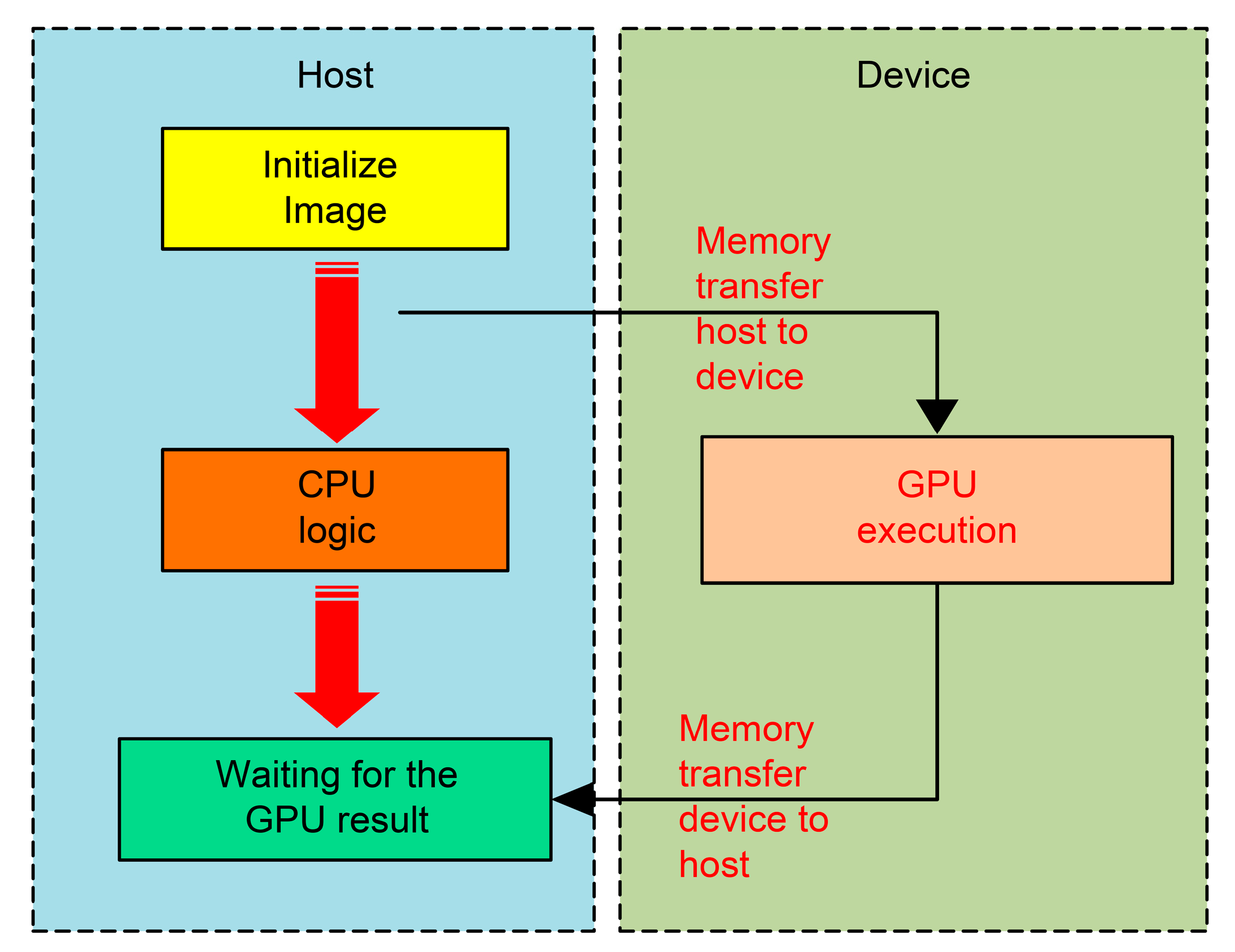
2.4. Basic Steps of GPU-Based Image Processing-Accelerated CUDA Program

The program can be divided into two aspects in CUDA architecture: the host side (responsible for completing complex instructions) and the device side (responsible for parallel completion of simple instructions). The host side runs on the central processing unit (CPU), whereas the device side runs on the GPU computing core. Programs running on the host side can be written in C and C++, whereas those on the device side must be built into the kernel. The general CUDA calculation process involves preparing the data to be processed on the host side, allocating storage space in the video memory, and transferring data to the video memory. The device side then performs the calculation, returns the completed results to the host side, and finally releases the video memory space [33]. The host side cannot directly manage the GPU video memory; therefore, the data transmission between the host and the device side must be realized by calling the CUDA runtime application programming interface. The data are transmitted back and forth simultaneously. As frequent back-and-forth data transmission between the host and the device is time-consuming and substantially reduces GPU execution efficiency, this type of operation should be avoided.
The host includes the CPU and host memory, and the device includes GPU and video memory. The GPU can help accelerate the CPU. The program runs on the host first and instructs the GPU to run when it encounters a device program.
The basic steps of an accelerating CUDA program with GPU image processing consist of allocating CPU memory and GPU video memory, transmitting data from the CPU to the GPU, and using the allocated grid and block to start the kernel function. After the CPU retrieves the results from the GPU, the CPU memory and GPU video memory are freed (Figure 4).

3. Methodology

This section introduces a detailed coarse-to-fine remote sensing image registration algorithm framework based on feature and optical flow theory and provides steps to implement the specific algorithm. The ORB feature point extraction and descriptor construction selected in the coarse registration stage are also introduced. Finally, the modified algorithm of demons correlation selected at the fine registration stage is introduced.

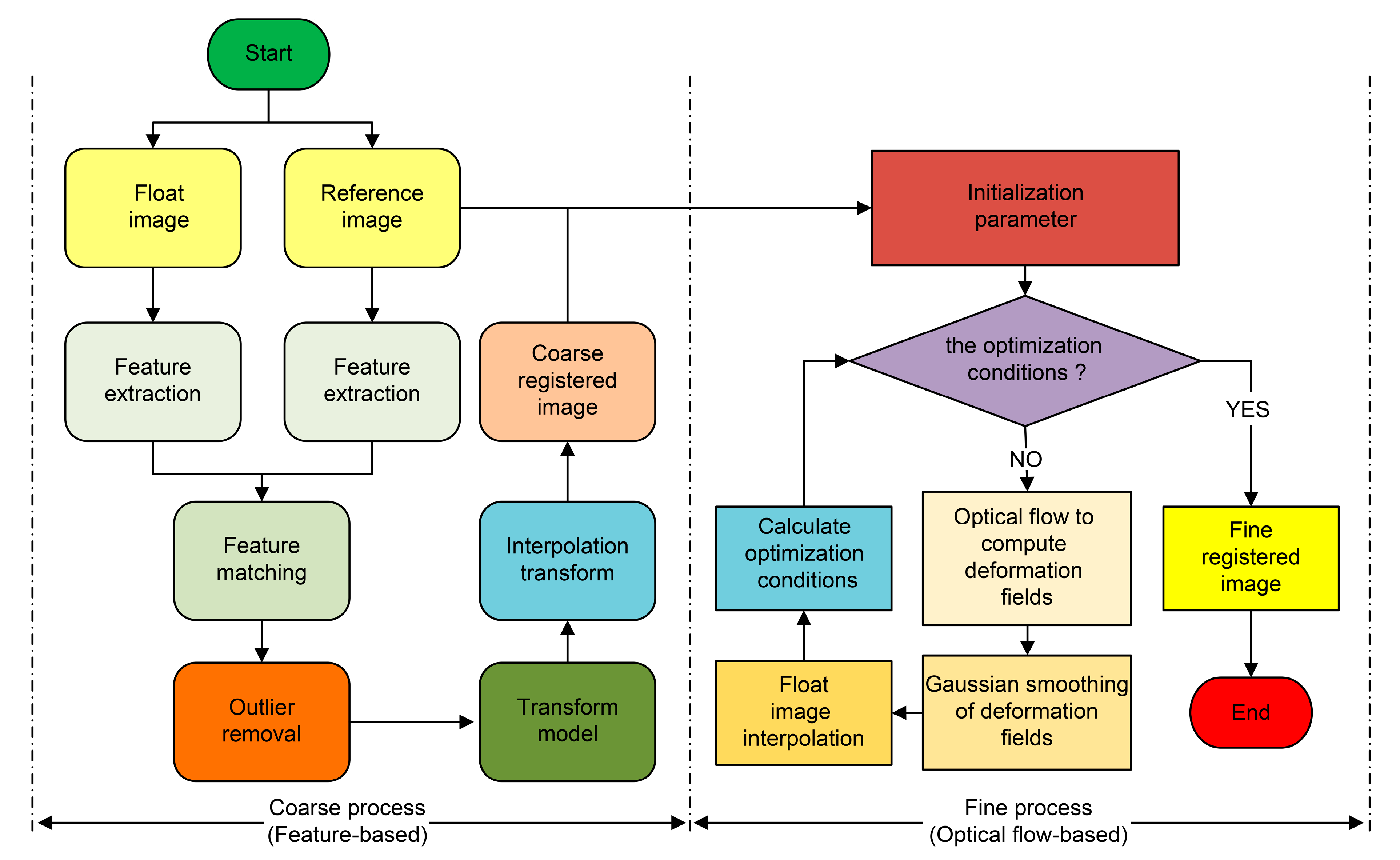
3.1. Algorithm Description

The framework of the registration algorithm is divided into two stages: a coarse registration stage based on the feature method and a fine registration stage based on optical flow theory (Figure 5).
The coarse registration stage involves the following:
  • At the beginning of registration, features of the floating and reference images, which can be one or a combination of Harris, Moravec, Haar-like, HOG, LBP, SIFT, SURF, BRIEF, SUSAN, FAST, CENSUS, FREAK, BRISK, ORB, etc., are extracted.
  • Extracted features are matched to obtain feature pairs of floating and reference images. This can be completed by brute force matching, which calculates the distance between a feature point descriptor and all other feature point descriptors, ranks the obtained distances, and selects the closest distance as the matching point.
  • The feature alignment exception matching is deleted using the exception elimination algorithm. Common methods include using a Hamming distance of less than twice the minimum distance, cross-matching, k-nearest neighbor matching, and random sampling consistency.
  • The transformation model from the floating image to the reference image is calculated using the matching feature of removing abnormal pairs.
  • The floating image is transformed to match the reference image by transforming the model and adopting appropriate interpolation transformation, thus obtaining the coarse registration result.
The fine registration stage involves the following:
  • The registration parameters are initialized. This may be the number of registration cycles, the similarity between the registered and reference images, or other parameters.
  • It is determined whether the registration optimization conditions are met.
  • If yes, the image is obtained after fine registration, and the process is completed.
  • If not, the method based on optical flow theory is used to calculate the deformation displacement field.
  • The deformation displacement field is subjected to Gaussian filtering.
  • The filtered deformation displacement field is used to interpolate the floating image.
  • The registration optimization conditions are calculated using normalization cross-correlation, mutual information, structure similarity index measure (SSIM), and difference in RMSE.
  • Return to (2) and continue to judge.
The registration problems associated with scale transformation, rotation, and other global transformations are mainly addressed at the coarse registration stage. In contrast, those associated with local image details are primarily resolved at the fine registration stage. The specific algorithm is described in the pseudo-code in Algorithm 1.
Algorithm 1: A specific algorithm for coarse-to-fine remote sensing image registration based on feature and optical flow theory
Input: floating image “image01”, reference image “image02”
Output: image after registration
1: Detect ORB feature point position
2: Calculate descriptor according to ORB feature point position
3: Perform feature point matching
4: Constrain the matching points to obtain excellent matching points
5: Using the matching points, calculate the projection mapping matrix from the floating image to the reference image
6: Use projection mapping matrix to complete rough image registration
7: Normalize the floating image and reference image after coarse registration and resize the square
8: Find the gradient of the reference image
9: Perform iteration operations as follows
10: Calculate coordinate offset code
11: Determine the gradient of floating image and improve the demons algorithm to determine the gradient
12: Perform Gaussian smoothing for coordinate offset to reduce burrs
13: Apply the pixel resampling code
14: Perform until convergence
15: Complete fine image registration

3.2. ORB Feature Point Extraction and Descriptor Construction

ORB is a rapid local feature detection operator proposed by Rublee et al. [45]. The ORB algorithm is an improved version of the original FAST and BRIEF algorithms [46], constructing a Gaussian pyramid and gray centroid to compensate for the scale and rotation invariances of the FAST algorithm and the rotation invariance of the BRIEF algorithm. The rotated BRIEF (RBRIEF) algorithm is used to construct the feature descriptor. The ORB algorithm has a fast-computing speed, strong real-time performance, and is insensitive to image noise.
ORB uses the FAST algorithm to detect image feature points. The FAST corner detection algorithm initially selects a central pixel (x, y) to draw a circle with a radius of 3 pixels and sets a threshold σ. The size of pixel points (x, y) is comparable to the 16-pixel values determined by the circumference in sequence. If the gray value of z pixel points on the circumference is >I (x, y) + σ or <I (x, y) − σ, then the selected pixel (x, y) is an image feature point, where I (x, y) represents the gray value of the pixel (x, y), and z is 9 or 12 [47].
It is necessary to obtain a principal direction for the feature to achieve feature points with rotation invariance. First, the feature points in the FAST corner set are taken as the center, and the gray centroid within a certain range of the feature is calculated. Then, a vector is constructed with the feature point and its gray centroid, and the main direction of the FAST feature point is obtained using the vector direction.
The neighborhood moments of feature points are defined as:
m p q = x , y x p y q I x , y ,
where I x , y   represents the gray value of each pixel   ( x , y ) in the image: p , q ( 0,1 ) .
The centroid of the neighborhood moment of the feature point is:
C = ( m 10 m 00 , m 01 m 00 ) .
The main direction of FAST feature points is expressed as:
θ = a r c t a n   ( m 01 m 10 ) .
The traditional ORB algorithm uses RBRIEF descriptors to extract binary descriptors from feature points, employing the main direction of feature points to determine the direction of binary descriptors. This addresses the issue of the lack of rotation invariance in BRIEF descriptors. The specific steps of this method are as follows:
First, a pixel block p with the size of N × N is selected after smoothing so that the gray values at the midpoint x , y of the pixel block are p ( x ) and p ( y ) . The binary test criterion τ is defined as:
τ p ; x , y = 1 , p ( x ) < p ( y ) 0 , p ( x ) p ( y ) .
A total of n pairs of position coordinates ( x i , y i ) are selected around the feature points. An n-dimensional binary feature code string is obtained by comparing the coordinates with the binary test criterion:
f n ( p ) = 1 i n 2 i 1 τ p ; x i , y i .
A matrix S of order 2 × n is defined as:
S = I , x 2 , . . . , x n I , y 2 , . . . , y n .
The principal direction of feature point θ corresponding to the rotation matrix R θ is:
R θ = c o s θ s i n θ s i n θ c o s θ .
The matrix S is rotated to obtain a new matrix, S θ :
S θ = R θ S = I .
Finally, the binary descriptor with a rotation invariant property is obtained as follows:
g n ( p , θ ) = f n ( p ) | ( x i , y i ) S θ .

3.3. Demons Correlation Algorithm

The demons algorithm is a registration method developed based on optical flow theory, which treats the iterative process of the algorithm as the process of each pixel in the floating image gradually spreading to the corresponding position in the reference image. The gray-value difference between the corresponding points of the two images is the external force of diffusion, whereas the gradient of the corresponding points of the reference image is the internal force of diffusion.
The offset (Ux, Uy) of point (x, y) in the reference image is calculated assuming that the reference image is S and the floating image is M, where Sx and Sy are gradients in the x and y directions, respectively, at point (x, y) in the reference image, and f is the gray-value difference between the reference image and the floating image at point (x, y).
U x = f × S x ( S x 2 + S y 2 ) + f 2 ,
U y = f × S y ( S x 2 + S y 2 ) + f 2 ,
f = S ( x , y ) M ( x , y ) .
Sx and Sy may be solved by various methods, including a Riemann–Liouville fractional differential algorithm [48], a Grumwald–Letnikov fractional differential edge detection algorithm [49], a Prewitt gradient operator, Scharr gradient operator, and Sobel operator as the gradient algorithm. The Sobel operator was selected here based on a comparison of performances.
The coordinate offset of the whole image is calculated to make the offset smooth and continuous in the global range and is Gaussian smoothed during each iteration to avoid image blurs after resampling.
Based on the original demon algorithm, Thirion proposed to increase the diffusion velocity coefficient α to control the size of coordinate offset (diffusion velocity), as shown in Formula (25) [50]. Registration accuracy in the iterative process of the algorithm usually increases with the number of iterations α:
U x = f × S x ( S x 2 + S y 2 ) + α 2 × f 2 ,
U y = f × S y ( S x 2 + S y 2 ) + α 2 × f 2 .
The active demons algorithm adds the gradient of the floating image to the offset calculation [51]. The internal force driving diffusion is the gradient of the reference image in the original algorithm. The gradient of the floating image was added as the new internal force to accelerate the convergence speed of iteration. The calculation offset is shown in the following formulae, where Mx and My are the gradients in the x and y directions at point (x, y) on the floating image, respectively.
U x = f × ( S x ( S x 2 + S y 2 ) + α 2 × f 2 + M x ( M x 2 + M y 2 ) + α 2 × f 2 ) ,
U y = f × ( S y ( S x 2 + S y 2 ) + α 2 × f 2 + S y ( M x 2 + M y 2 ) + α 2 × f 2 ) .
The inertial demons algorithm was proposed on the basis of an active demons algorithm. Here, the offset calculated by the previous iteration is added to the offset of the current iteration to further improve the convergence speed and registration accuracy [52]. Its calculation is shown in the following formula, where k is the current number of iterations, and the value of the coefficient β is between 0 and 1:
U x = β × U x k 1 + f × ( S x ( S x 2 + S y 2 ) + α 2 × f 2 + M x ( M x 2 + M y 2 ) + α 2 × f 2 ) ,
U y = β × U x k 1 + f × ( S y ( S x 2 + S y 2 ) + α 2 × f 2 + S y ( M x 2 + M y 2 ) + α 2 × f 2 ) .

4. Experiments and Discussion
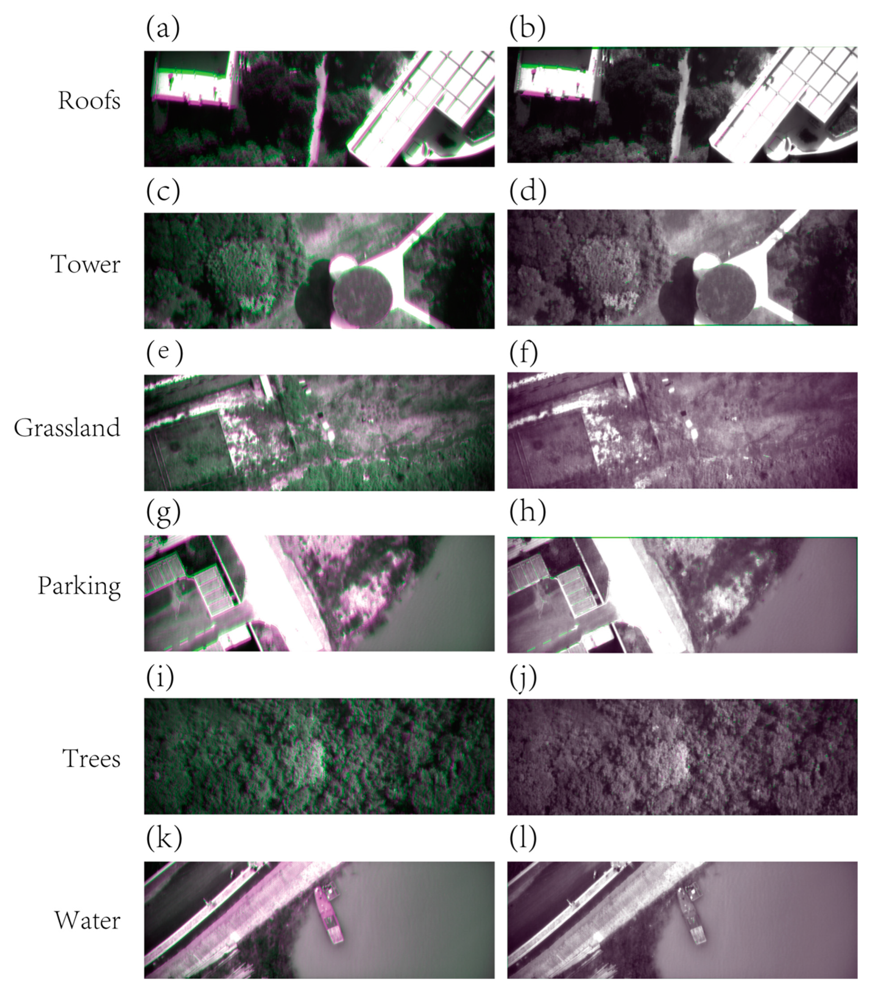
This section introduces the datasets and evaluation criteria. Then, the speed, registration rate, and robustness of 13 currently popular algorithms (ORB, KAZE, AKAZE, BRISK, optical flow method demons, B-spline-based free-form deformation algorithm, FAST, ECC, SIFT-FSC, SURF-GTM, SIFT, SURF, and VGG16) were compared in the registration of actual UAV remote sensing spectral data to evaluate the performance of the proposed method. Finally, a real-time processing experiment was conducted using UAVs for remote sensing flights.
Our algorithm runs on a 2.8–4.7 GHz Core i7-1165G7 quad-core 8-threaded processor with 16 GB RAM, an Nvidia RTX2060 independent video card, and 6 GB GDDR6 video memory. CUDA 11.4 was used under Microsoft Windows 10. The performance of the registration process of all images on the GPU and CPU was compared. The GPU implementation was written in CUDA, and the CPU version was written in standard C.

4.1. Datasets

The AOTF spectral airborne datasets 1–6 were derived from AOTF unmanned aerial remote sensing for different scenarios corresponding to roofs, towers, grassland, parking, trees, and water. The drone flew at an altitude of 100 m, capturing images in two adjacent spectral wavelengths of 580 and 620 nm. The images have a size of 2048 × 680 pixels and are shown in Figure 6.

4.2. Evaluation Criteria

SSIM [53], RMSE [54], MI [55], UIQI [56], and SAM [57] were used to evaluate the effects of different algorithms and their execution in CPU and GPU.
1.
SSIM
SSIM is an index to indicate the similarity between two images. It can measure the difference between the enhanced and real image to guide the learning process. The formula of SSIM is as follows:
S S I M ( x , y ) = ( 2 μ x μ y + c 1 ) ( 2 σ x y + c 2 ) ( μ x 2 + μ y 2 + c 1 ) ( σ x 2 + σ y 2 + c 2 ) ,
where x and y are the two input images, μ x and μ y represent their respective averages, σ x 2 and σ y 2 represent their respective covariances, and c 1 and c 2 are constants with a denominator of 0. The values of SSIM range between 0 and 1, where 1 denotes two identical images. Thus, a larger value indicates that more details from the original two images have been retained.
2.
RMSE
A smaller RMSE value indicates better results, implying fewer differences between the generated image and the original two images and the retention of more details.
R M S E = 1 M × N i = 0 , j = 0 M 1 , N 1 I 1 ( i , j ) I 2 ( i , j ) 2 ,
where M and N are the height and width of the image, respectively, I 1 ( i , j ) is the pixel value of the reference image at position ( i , j ) , and I 2 ( i , j ) is the pixel value of the registered image at position ( i , j ) .
3.
MI
Mutual information (MI) is an important concept in information theory that describes the correlation between two systems or the amount of information they contain. In image registration, the mutual information between two images reflects the degree of mutual inclusion of information between them through their entropy and joint entropy. For images I 1 and I 2 , their mutual information is represented as:
M I ( I 1 , I 2 ) = H ( I 1 ) + H ( I 2 ) H ( I 1 , I 2 ) ,
where H ( I 1 ) and H ( I 2 ) are the entropy of images I 1 and I 2 , and H ( I 1 , I 2 ) is the joint entropy of images I 1 and I 2 . When the similarity between two images is higher or the overlap is greater, their correlation is stronger, and the joint entropy is smaller, which means the mutual information is greater.
4.
UIQI
Universal image quality index (UIQI) is a universal objective quality evaluation index for images, for which the distortion of an image is determined by three factors: correlation distortion, brightness distortion, and contrast distortion. Although this indicator is not associated with the human visual system, its effectiveness is significantly higher than the evaluation accuracy of traditional full reference image quality objective evaluation indicators, such as the root mean square error and peak signal-to-noise ratio. Assuming X is the original image, and Y is the image to be evaluated, then UIQI is expressed as:
U I Q I = σ X Y σ X σ Y 2 μ X μ Y μ X 2 + μ Y 2 2 σ X σ Y σ X 2 + σ Y 2 .
The range of UIQI in the formula is [−1, 1], where −1 is the worst effect, and 1 is the best effect, indicating that the image to be evaluated has no distortion; μ X and σ X 2 are the mean and variance of the original image pixel values, respectively; μ Y and σ Y 2 are the mean and variance of the pixel values of the image to be evaluated, respectively; σ X Y is the covariance between the pixel values of the original image and the image to be evaluated.
5.
SAM
The similarity between a test spectrum (pixel spectrum) and a reference spectrum can be determined by calculating the “angle” between them. SAM can also be used to calculate the similarity between two arrays, and its calculation result can be seen as the cosine angle between the two arrays. The calculation formula is as follows:
S A M = c o s 1 d T x d T d × x T x ,
where d is the given target array, and x is the array to be tested. The smaller the output value, the more similar the two arrays; the larger the distance between two arrays, the lower the similarity.

4.3. Ground Experiment Results and Analysis

FSC [58], SURF-GTM [59], SIFT [60], SURF [61], and VGG16 [3] were compared in terms of speed, registration rate, robustness, and other characteristics in the registration of actual UAV remote sensing spectral data.
The proposed registration algorithm yielded SSIM parameters of the registered and reference images that were closer to 1 for the six groups of image pairs than for the other methods, and it produced the best registration effect (Table 2). The registration algorithms based on optical flow theory (demons and FFD algorithms) showed advantages over other algorithms, except in the Cars dataset. For the tested dataset, the VGG16 algorithm based on artificial intelligence and machine learning did not show substantial advantages over algorithms based only on features.
A comparison of the RMSEs of different registration algorithms (Table 3) showed that the proposed algorithm yielded the smallest error among the algorithms for all datasets. VGG16 again showed no substantial advantages over other algorithms. The error of the demons algorithm was smaller than that of the FFD algorithm. With the exception of the water dataset, the feature-based ECC algorithm performed better than the other feature-based algorithms.
A comparison of the MIs of different registration algorithms (Table 4) showed that the algorithm proposed in this article has the highest mutual information value between the registered image and reference image on the selected six datasets. The demons algorithm based on the optical flow comb theory also has advantages in addition to the Cars dataset. Except for the algorithm proposed in this article and the demons algorithm, the registration results of other registration algorithms were relatively similar.
The registration effect of the proposed algorithm for eight image pairs is shown in Figure 7 in the form of image overlays. The left column of the figure shows the images to be registered superimposed on the reference images. The large difference between the images results in a small area of overlap; areas of difference are displayed in pseudo-color. The left column shows the same superposition after image registration. As the generated images are now closer to the reference images, the area of overlap is large, and the pseudo-colored area of difference is small.
In order to display the registered image and reference image, and the details after registration, a chessboard is used to alternately display the reference image, the registered image, and their details are displayed. The condition for selecting a detailed map is to select a continuous feature on the ground. If the registration is correct, the features in the detail map will be continuous. If the registration is not correct, the ground scenery will be misaligned, as shown in Figure 8 below.
The proposed algorithm performed well in all six datasets compared with the five other registration algorithms (Figure 8). The VGG16 algorithm sourced from the literature did not demonstrate noticeable performance; the feature-based SIFT-FSC and SURF-GTM algorithms yielded similar results and were not considered ideal. The optical flow theory algorithms (FFD and demons) generally performed well, but the FFD algorithm deformed images in the Cars and Roofs datasets to varying degrees after registration.
A CUDA architecture VS2023+CUDA+OPENCV development environment was built to accelerate the processing algorithm and enable the comparison of runtimes between a CPU-only and a CPU+GPU processing architecture to meet the requirements of real-time remote sensing processing using the AOTF spectrometer. The images used in this test had the same number of features (100) or the same registration accuracy. Two FFD cycles and 30 calculation cycles were used.
Even when using only two cycles, the FFD algorithm took the longest time (Table 5) due to the time complexity of the B-spline-based FFD algorithm of m×n×16×[c+3]×[r+3]×2 ≈ O (n4). Without CUDA, the computation load was substantial. The demons algorithm (based on optical flow theory) achieved a large acceleration ratio. The feature-based FAST, ORB, and SURF algorithms were relatively rapid on the CPU platform and thus did not achieve an increase in CPU+GPU. The proposed CPU+GPU algorithm achieved an acceleration ratio of ~30 times relative to that of the CPU alone. Furthermore, the absolute registration time of the two spectral segments and the feature-based algorithm remained in the same order of magnitude, and the average registration time was ~0.5 s. This indicates that the proposed method can potentially enable real-time processing of remote sensing hyperspectral data.

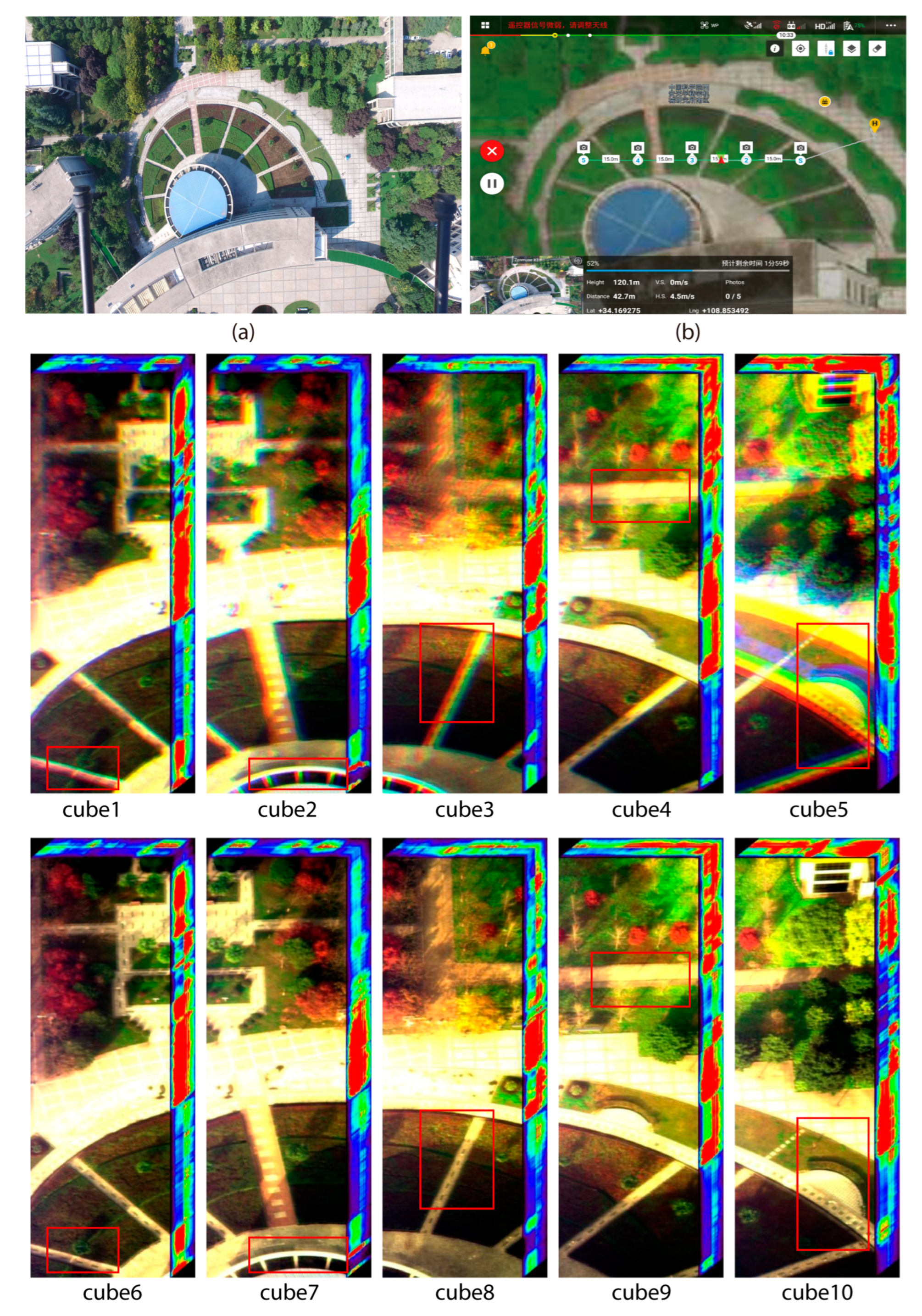
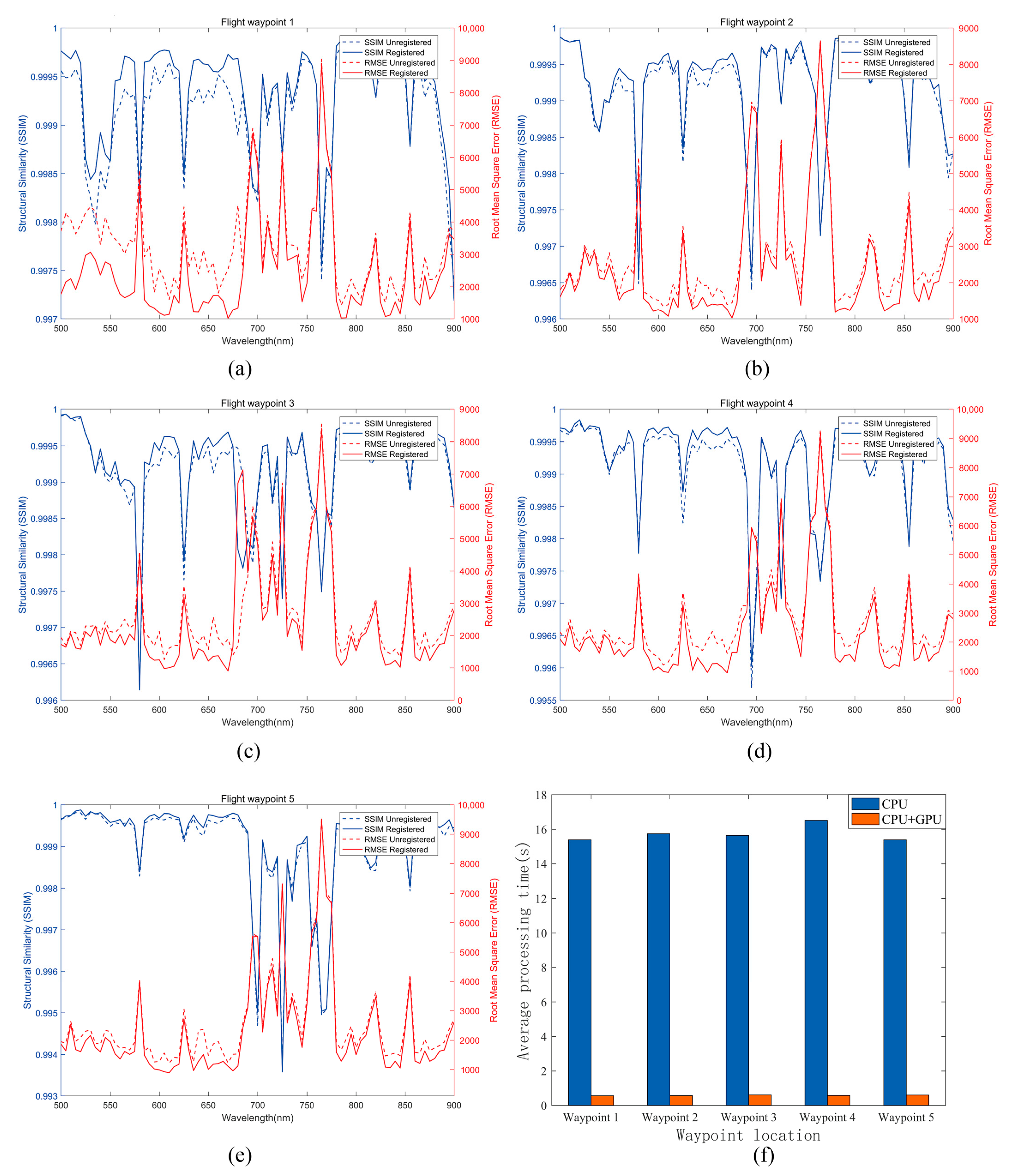
4.4. Real-Time Processing of the Remote Sensing Imaging Registration Experiment for Unmanned Aerial Vehicles

The waypoint acquisition procedure was modified, and the registration procedure was added to verify that the zoom lens-based AOTF spectrometer could register the collected airborne spectral imaging data cube in real time. A UAV experiment was conducted at the Xi’an Institute of Optics and Precision Mechanics, Chinese Academy of Sciences (34°10′3.12″ N, 108°51′28.67″ E) on 22 November 2023. Five flight waypoints were selected during one flight to collect five spectral data cubes. The flight altitude was 100 m, the trigger dwell time at a waypoint was 70 s, the wavelength switching step of the spectral data cube was 5 nm from 400–1000 nm, and 121 bands of data acquisition and registration were completed.
The proposed registration algorithm was adopted for image processing. Taking into account the registration effect and computation time, through multiple experiments, it was determined to set the number of extracted features to 100 and the registration iteration number to 30. A micro airborne processing platform with GPU was used to verify the effect of onboard real-time processing in terms of registration accuracy and registration time.
The registration time between two spectral bands was approximately 0.5 s (Table 5); thus, the alignment time required to complete all spectral bands was 120 × 0.5 = 60 s. The frame rate was set to 2 Hz accordingly. Since the time between waypoints was 74 s (waypoint stay of 70 s + flight time of 4 s [20 m at 5 m/s]), data acquisition of 121 spectral bands of the AOTF spectrometer and the registration of the whole data cube could be completed at each waypoint using the CPU+GPU processing mode.
The unregistered data cubes (1–5) in Figure 9 exhibited varying patterns for the three spectral segments (R: 650 nm, G: 530 nm, and B: 480 nm) of synthetic pseudo-color, suggesting that images of different spectral segments have varying fields of view for three reasons: (1) image size deformation caused by zoom, (2) image drift caused by wavelength switching, and (3) UAV platform jitter in remote sensing applications. Data cubes 6–10 in Figure 9 were registered using the proposed coarse-to-fine remote sensing image registration framework based on features and optical flow theory. Parallel processing of the CUDA architecture provided rapid registration, verifying the potential of this technique for real-time processing.
Figure 10 shows a quantitative comparison of the registration effect of waypoint data cubes and GPU registration acceleration.
Figure 10a–e shows the SSIM and RMSE between adjacent wavelengths before and after registration for the five selected waypoints in the form of curves. The SSIM between adjacent bands of the data cube after registration using the proposed algorithm was considerably greater than without registration. The RMSE of the data cube after registration was smaller than without registration.
Figure 10f compares registration time between the CPU platform and the CPU+GPU platform. Here, the registration algorithm of the five data cubes was reused offline after the flight test was completed. It can be seen from the comparative bar chart that the average processing time of adjacent spectral segments at five waypoints is approximately 15 s using CPU and 0.5 s using CPU+GPU. Therefore, the CPU+GPU processing architecture achieves approximately 30 times faster acceleration.
Finally, the hyperspectral data cube captured at the third waypoint of the experimental data was registered, and the registration performance of the algorithm proposed in this paper was compared with the algorithms in the reference literature. The comparison results are shown in Table 6, which compares the performance of different algorithms in achieving data cube registration.
The registration results of different registration algorithms on data cube 3 are shown in Table 6. This article proposes a new coarse-to-fine remote sensing image registration method based on feature and optical flow theory. The registered data cubes demonstrate strong performance in terms of the SSIM, RMSE, MI, UIQI, and SAM values. Therefore, the method proposed in this article is highly appropriate for completing the registration of unmanned aerial vehicle hyperspectral remote sensing image data cubes based on AOTF spectral imager.
Currently, verification has been completed on five waypoints in a flight experiment. However, it is necessary to complete all processing steps, including concatenation of all waypoints, operation between spectral bands, and inversion of some application parameters. The processing capacity of the platform is subject to certain limitations. The processing platform with the selected GPU is currently the smallest processing platform available. If the processing platform is too large, it will be limited by the maximum takeoff weight and range of the drone. The AOTF spectral scanning imaging spectrometer has a unique advantage in selecting spectral bands. By selecting the bands of interest in the later stage and reducing the number of bands for data processing, there is potential for completing real-time hyperspectral remote sensing processing for a specific application.

5. Conclusions

A zoom lens-based AOTF spectral imager has the capability to address the issues of image blurring and spectral segment drift in remote sensing. However, image size deformation caused by zoom, image drift caused by wavelength switching, and UAV platform jitter cause slight field-of-view differences in images of adjacent spectral segments. Therefore, registration of each spectral segment is required to use these data.
A new coarse-to-fine remote sensing image registration framework based on feature and optical flow theory was proposed in this study. The issues of scale transformation, rotation, and other overall transformations were mainly addressed in the coarse registration stage, whereas issues with local image details were primarily addressed in the fine registration stage.
The proposed method was compared with current algorithms to assess its relative performance. We found the algorithm suitable for distributed and parallel processing in the fine registration stage. The algorithm’s acceleration effect was verified in a CUDA architecture (VS2023+CUDA+OPENCV) development environment.
AOTF spectral imager data were then registered in real-time during waypoint shooting, following suitable modification of the data acquisition and processing program on the unmanned aerial remote sensing platform. This proved that the proposed algorithm and the CPU+GPU platform meet the requirements of real-time registration and processing on a UAV.
Certain potential issues and limitations should be considered regarding our findings. First, it remains unknown whether increasing the number of iterations might impact the spectral energy information. Second, although the proposed algorithm achieved a relative acceleration effect of ~30 times, the absolute registration time of a group of images should be further shortened to better implement this methodology.
Several future developments are planned for the developed system. First, the effects on the spectral energy and the spectral information with an increased number of iterations when using the coarse-to-fine registration framework of the feature + optical flow method will be further investigated. Second, we will elucidate whether implementing OpenMP multithreading technology for some serial programs by the CPU and using OpenGL can improve real-time performance. Finally, research on data cube splicing will be carried out based on data cube registration.

Author Contributions

Conceptualization: H.L., B.H., and X.H.; data curation: H.L.; formal analysis: H.L. and Z.Z.; funding acquisition: T.Y. and X.H.; investigation: H.L. and T.Y.; methodology: H.L. and T.Y.; project administration: T.Y.; resources: B.H. and T.Y.; software: X.L.; supervision: B.H. and T.Y.; validation: J.L.; visualization: X.W.; writing—original draft: H.L. All authors have read and agreed to the published version of the manuscript.

Funding

This research was funded by a Class A plan from a major strategic pilot project of the Chinese Academy of Sciences, grant number XDA23040101; the National Natural Science Foundation of China, grant numbers 61872286 and 62272376; the Key R&D Program of Shaanxi Province of China, grant numbers 2020ZDLGY04-05 and S2021-YF-YBSF-0094; the Shaanxi Key Laboratory of Deep Space Exploration Intelligent Information Technology, grant number 2021SYS-04; the National Key R&D Program of China, grant number 2017YFC1403700; the “Light of the west” project of the Chinese Academy of Sciences, grant number XAB2017B25; and the Photon project, grant number S24-030-III.

Data Availability Statement

No new data were created or analyzed in this study. Data sharing is not applicable to this article. The code for the algorithm used in this study can be accessed at https://github.com/6red/DOC.git on 16 July 2024.

Conflicts of Interest

The authors declare no conflicts of interest.

References

  1. Li, X.; Ai, W.; Feng, R.; Luo, S. Survey of remote sensing image registration based on deep learning. Natl. Remote Sens. Bull. 2023, 27, 267–284. [Google Scholar] [CrossRef]
  2. Jiang, J.; Shi, X. A robust point-matching algorithm based on integrated spatial structure constraint for remote sensing image registration. IEEE Geosci. Remote Sens. Lett. 2016, 13, 1716–1720. [Google Scholar] [CrossRef]
  3. Yang, Z.; Dan, T.; Yang, Y. Multi-temporal remote sensing image registration using deep convolutional features. IEEE Access 2018, 6, 38544–38555. [Google Scholar] [CrossRef]
  4. Mo, Y.; Kang, X.; Duan, P.; Li, S. A robust UAV hyperspectral image stitching method based on deep feature matching. IEEE Trans. Geosci. Remote Sens. 2022, 60, 1–14. [Google Scholar] [CrossRef]
  5. Ordóñez, A.; Acción, Á.; Argüello, F.; Heras, D.B. HSI-MSER: Hyperspectral image registration algorithm based on MSER and SIFT. IEEE J. Sel. Top. Appl. Earth Obs. Remote Sens. 2021, 14, 12061–12072. [Google Scholar] [CrossRef]
  6. Chen, H.; Zhang, H.; Du, J.; Luo, B. Unified framework for the joint super-resolution and registration of multiangle multi/hyperspectral remote sensing images. IEEE J. Sel. Top. Appl. Earth Obs. Remote Sens. 2020, 13, 2369–2384. [Google Scholar] [CrossRef]
  7. Lu, B.; Dao, P.D.; Liu, J.; He, Y.; Shang, J. Recent advances of hyperspectral imaging technology and applications in agriculture. Remote Sens. 2020, 12, 2659. [Google Scholar] [CrossRef]
  8. Syed Taimoor Hussain Shah, S.A.Q.; ul Rehman, A. Classification and Segmentation Models for Hyperspectral Imaging—An Overview. In Intelligent Technologies and Applications; Springer: Cham, Switzerland, 2021; Volume 1382. [Google Scholar] [CrossRef]
  9. Wang, J.; Ding, N.; Zheng, Y.; Zhao, Y.; Gao, F.; Li, J.; Wang, J.; Gao, M.; Wu, J. Overall design technology of hyperspectral imaging system based on AOTF. In Proceedings of the International Symposium on Optoelectronic Technology and Application 2014: Imaging Spectroscopy; and Telescopes and Large Optics, Beijing, China, 18 November 2014. [Google Scholar]
  10. Nag, S.; Hewagama, T.; Georgiev, G.T.; Pasquale, B.; Aslam, S.; Gatebe, C.K. Multispectral snapshot imagers onboard small satellite formations for multi-angular remote sensing. IEEE Sens. J. 2017, 17, 5252–5268. [Google Scholar] [CrossRef]
  11. Jaiswal, B.; Singh, S.; Jain, A.; Sankarasubramanian, K.; Nandi, A. AOTF based spectro-polarimeter for observing Earth as an Exoplanet. arXiv 2023, arXiv:2302.10712. [Google Scholar] [CrossRef]
  12. Sharikova, M.O.; Balandin, I.A.; Batshev, V.I.; Kozlov, A.B. Spatial and spectral correction of an acousto-optical imaging spectrometer. J. Opt. Technol. 2023, 90, 684–690. [Google Scholar] [CrossRef]
  13. Zhang, H.; Zhao, H. Accurate design of a TeO2 noncollinear acousto-optic tunable filter with refractive index correction. Opt. Lett. 2023, 48, 3395–3398. [Google Scholar] [CrossRef]
  14. Zhao, H.; Cheng, C.; Guo, Q.; Ma, R.; Yang, Y. Analysis of phase mismatch for mercurous bromide-based non-collinear AOTF design in spectral imaging applications. Materials 2024, 17, 1703. [Google Scholar] [CrossRef]
  15. Yu, K.; Guo, Q.; Li, N.; Cheng, C.; Zhao, H. Spectral calibration method for mid-infrared AOTF imagers. Infrared Laser Eng. 2023, 52, 20230291. [Google Scholar] [CrossRef]
  16. Liu, H.; Hou, X.; Hu, B.; Yu, T.; Zhang, Z.; Liu, X.; Liu, J.; Wang, X.; Zhong, J.; Tan, Z. Image blurring and spectral drift in imaging spectrometer system with an acousto-optic tunable filter and its application in UAV remote sensing. Int. J. Remote Sens. 2022, 43, 6957–6978. [Google Scholar] [CrossRef]
  17. Tondewad, P.S.; Dale, M.P. Remote sensing image registration methodology: Review and discussion. Procedia Comput. Sci. 2020, 171, 2390–2399. [Google Scholar] [CrossRef]
  18. Li, L.; Han, L.; Ding, M.; Cao, H.; Hu, H. A deep learning semantic template matching framework for remote sensing image registration. ISPRS J. Photogramm. Remote Sens. 2021, 181, 205–217. [Google Scholar] [CrossRef]
  19. Ruiqi, L.; Bowu, Y.; Dou, Q.; Yi, L.; Baorui, D.; Shuang, W.; Huarong, J.; Biao, H.; Licheng, J. Deep Global Feature-Based Template Matching for Fast Multi-Modal Image Registration. In Proceedings of the 2021 IEEE International Geoscience and Remote Sensing Symposium IGARSS, Brussels, Belgium, 11–16 July 2021; pp. 5457–5460. [Google Scholar]
  20. Ye, Y.; Wang, M.; Hao, S.; Zhu, Q. A novel keypoint detector combining corners and blobs for remote sensing image registration. IEEE Geosci. Remote Sens. Lett. 2021, 18, 451–455. [Google Scholar] [CrossRef]
  21. Wu, G.-L.; Chang, H.-H. An accurate feature point matching algorithm for automatic remote sensing image registration. In Proceedings of the International Conference on Digital Image Computing: Techniques and Applications (DICTA), Sydney, Australia, 29 November–1 December 2017. [Google Scholar] [CrossRef]
  22. Zhang, T.; Zhao, R.; Chen, Z. Application of migration image registration algorithm based on improved SURF in remote sensing image mosaic. IEEE Access 2020, 8, 163637–163645. [Google Scholar] [CrossRef]
  23. Chen, S.; Zhong, S.; Xue, B.; Li, X.; Zhao, L.; Chang, C.-I. Iterative scale-invariant feature transform for remote sensing image registration. IEEE Trans. Geosci. Remote Sens. 2021, 59, 3244–3265. [Google Scholar] [CrossRef]
  24. Jhan, J.-P.; Rau, J.-Y. A generalized tool for accurate and efficient image registration of UAV multi-lens multispectral cameras by N-SURF matching. IEEE J. Sel. Top. Appl. Earth Obs. Remote Sens. 2021, 14, 6353–6362. [Google Scholar] [CrossRef]
  25. Wu, Y.; Xiao, Z.; Liu, S.; Miao, Q.; Ma, W.; Gong, M.; Xie, F.; Zhang, Y. A two-step method for remote sensing images registration based on local and global constraints. IEEE J. Sel. Top. Appl. Earth Obs. Remote Sens. 2021, 14, 5194–5206. [Google Scholar] [CrossRef]
  26. Ordóñez, Á.; Argüello, F.; Heras, D.B. GPU accelerated FFT-based registration of hyperspectral scenes. IEEE J. Sel. Top. Appl. Earth Obs. Remote Sens. 2017, 10, 4869–4878. [Google Scholar] [CrossRef]
  27. Liu, Y.; Cao, H.; Zhao, Y.; He, Q.; Yang, Y.; Wang, L.; Lin, G.; Zhou, J. A remote sensing image registration algorithm based on multiple constraints and a variational Bayesian framework. Remote Sens. Lett. 2021, 12, 296–305. [Google Scholar] [CrossRef]
  28. Zhou, C.; Zhang, G.; Yang, Z.; Zhou, J. A novel image registration algorithm using wavelet transform and matrix-multiply discrete Fourier transform. IEEE Geosci. Remote Sens. Lett. 2022, 19, 8002605. [Google Scholar] [CrossRef]
  29. Lee, W.; Sim, D.; Oh, S.-J. A CNN-based high-accuracy registration for remote sensing images. Remote Sens. 2021, 13, 1482. [Google Scholar] [CrossRef]
  30. Zeng, Y.; Ning, Z.; Liu, P.; Luo, P.; Zhang, Y.; He, G. A mosaic method for multi-temporal data registration by using convolutional neural networks for forestry remote sensing applications. Computing 2020, 102, 795–811. [Google Scholar] [CrossRef]
  31. Ye, Y.; Tang, T.; Zhu, B.; Yang, C.; Li, B.; Hao, S. A multiscale framework with unsupervised learning for remote sensing image registration. IEEE Trans. Geosci. Remote Sens. 2022, 60, 5622215. [Google Scholar] [CrossRef]
  32. Ying, C.; Lei, C.; Qi, Z.; Wei, W.; Jiahao, W. Improved remote sensing image registration of residual block densely connected network based on reinforcement learning. In Proceedings of the 6th International Conference on Intelligent Informatics and Biomedical Sciences (ICIIBMS), Oita, Japan, 25–27 November 2021. [Google Scholar] [CrossRef]
  33. Fernández-Fabeiro, J.; Gonzalez-Escribano, A.; Llanos, D.R. Distributed programming of a hyperspectral image registration algorithm for heterogeneous GPU clusters. J. Parallel Distrib. Comput. 2021, 151, 86–93. [Google Scholar] [CrossRef]
  34. Liu, Y.; Zhou, Y.; Zhou, Y.; Ma, L.; Wang, B.; Zhang, F. Accelerating SAR image registration using swarm-intelligent GPU parallelization. IEEE J. Sel. Top. Appl. Earth Obs. Remote Sens. 2020, 13, 5694–5703. [Google Scholar] [CrossRef]
  35. Ordóñez, Á.; Heras, D.B.; Argüello, F. Multi-GPU registration of high-resolution multispectral images using HSI-KAZE in a cluster system. In Proceedings of the 2022 IEEE International Geoscience and Remote Sensing Symposium (IGARSS), Kuala Lumpur, Malaysia, 17–22 July 2022. [Google Scholar] [CrossRef]
  36. Zhang, X.; Zhao, X. High-precision registration algorithm and parallel design method for high-resolution optical remote sensing images. Int. J. Pattern Recognit. Artif. Intell. 2021, 35, 2154020. [Google Scholar] [CrossRef]
  37. Jiang, Q.; Qiu, Y.; Wen, Y.; Wang, H.; Xu, W. Design of data acquisition system for AOTF polarization spectral imaging instrument. Infrared Laser Eng. 2012, 41, 218–222. [Google Scholar]
  38. Liu, H.; Yu, T.; Hu, B.; Hou, X.; Zhang, Z.; Liu, X.; Liu, J.; Wang, X.; Zhong, J.; Tan, Z.; et al. UAV-borne hyperspectral imaging remote sensing system based on acousto-optic tunable filter for water quality monitoring. Remote Sens. 2021, 13, 4069. [Google Scholar] [CrossRef]
  39. Jiachun, W.; Dapeng, Z.; Xianghua, D.; Qichao, W.; Zhigang, L. Design and experiment of hyper-spectral polarization imaging system based on AOTF. Infrared Laser Eng. 2017, 46, 1136002. [Google Scholar] [CrossRef]
  40. Ryu, S.Y.; You, J.-W.; Kwak, Y.; Kim, S. Design of a prism to compensate the image-shifting error of the acousto-optic tunable filter. Opt. Express 2008, 16, 17138–17147. [Google Scholar] [CrossRef]
  41. Ren, Y.; Cai, H.; Tan, J.; Tan, Y.; Zhang, X.; Zheng, F.; Ma, W. Imaging drift of acousto-optic modulator spectral camera. Chin. Opt. 2013, 6, 179–186. [Google Scholar] [CrossRef]
  42. Suhre, D.R.; Theodore, J.G. White-light imaging by use of a multiple passband acousto-optic tunable filter. Appl. Opt. 1996, 35, 4494–4501. [Google Scholar] [CrossRef]
  43. Feng, R.; Du, Q.; Luo, H.; Shen, H.; Li, X.; Liu, B. A registration algorithm based on optical flow modification for multi-temporal remote sensing images covering the complex-terrain region. Nation Remote Sens. Bull. 2021, 25, 630–640. [Google Scholar] [CrossRef]
  44. Horn, B.K.P.; Schunck, B.G. Determining optical flow. Artif. Intell. 1981, 17, 185–203. [Google Scholar] [CrossRef]
  45. Rublee, E.; Rabaud, V.; Konolige, K.; Bradski, G. ORB: An efficient alternative to SIFT or SURF. In Proceedings of the 2011 International Conference on Computer Vision, Barcelona, Spain, 6–13 November 2011. [Google Scholar] [CrossRef]
  46. Tang, M.; Liang, K.; Qiu, J. Small insulator target detection based on multi-feature fusion. IET Image Proc. 2023, 17, 1520–1533. [Google Scholar] [CrossRef]
  47. Lei, S.; Zhu, F. UAV remote sensing image registration algorithm based on ORB and improved RANSAC. J. Nat. Sci. Heilongjiang Univ. 2020, 37, 8. [Google Scholar] [CrossRef]
  48. Zhang, G.; Guo, L.; Xiong, B.; Chu, J. Active demons algorithm based on multi-resolution and adaptive fractional differential. J. Comput. Res. Dev. 2018, 55, 2753–2763. [Google Scholar] [CrossRef]
  49. Chen, Q.; Liu, J.; Tang, Z.-H.; Li, J.-Q.; Wu, M. Detection and extraction of image edge curves and detailed features using fractional differentiation. Acta Electron. Sin. 2013, 41, 1873–1880. [Google Scholar] [CrossRef]
  50. Thirion, J.P. Image matching as a diffusion process: An analogy with Maxwell’s demons. Med. Image Anal. 1998, 2, 243–260. [Google Scholar] [CrossRef] [PubMed]
  51. Wang, H.; Dong, L.; O’Daniel, J.; Mohan, R.; Garden, A.S.; Ang, K.K.; Kuban, D.A.; Bonnen, M.; Chang, J.Y.; Cheung, R. Validation of an accelerated ‘demons’ algorithm for deformable image registration in radiation therapy. Phys. Med. Biol. 2005, 50, 2887. [Google Scholar] [CrossRef] [PubMed]
  52. Santos-Ribeiro, A.; Nutt, D.J.; McGonigle, J. Inertial demons: A momentum-based diffeomorphic registration framework. In Medical Image Computing and Computer-Assisted Intervention-MICCAI 2016; Ourselin, S., Joskowicz, L., Sabuncu, M., Unal, G., Wells, W., Eds.; Springer Nature: Cham, Switzerland, 2016; pp. 37–45. [Google Scholar]
  53. Peng, M.; Li, G.; Zhou, X.; Ma, C.; Zhang, L.; Zhang, X.; Shang, K. A registration-error-resistant swath reconstruction method of ZY1-02D satellite hyperspectral data using SRE-ResNet. Remote Sens. 2022, 14, 5890. [Google Scholar] [CrossRef]
  54. Gu, Y.; Wang, C.; Li, X. An intensity-independent stereo registration method of push-broom hyperspectral scanner and LiDAR on UAV platforms. IEEE Trans. Geosci. Remote Sens. 2022, 60, 5540014. [Google Scholar] [CrossRef]
  55. Bin, J.; Zhang, H.; Bahrami, Z.; Zhang, R.; Liu, H.; Blasch, E.; Liu, Z. The registration of visible and thermal images through multi-objective optimization. Inf. Fusion 2023, 95, 186–198. [Google Scholar] [CrossRef]
  56. Wang, S.; Fan, F. Thangka. Hyperspectral image super-resolution based on a spatial-spectral integration network. Remote Sens. 2023, 15, 3603. [Google Scholar] [CrossRef]
  57. Guo, A.; Dian, R.; Li, S. A deep framework for hyperspectral image fusion between different satellites. IEEE Trans. Pattern Anal. Mach. Intell. 2023, 45, 7939–7954. [Google Scholar] [CrossRef]
  58. Fan, Y.G.; Chai, J.; Xu, M.; Wang, B.; Hou, Q. Improved fast Image registration algorithm based on ORB and RANSAC fusion. Opt. Precis. Eng. 2019, 27, 702–717. [Google Scholar] [CrossRef]
  59. Ordóñez, Á.; Argüello, F.; Heras, D.B.; Demir, B. GPU-accelerated registration of hyperspectral images using KAZE features. J. Supercomput. 2020, 76, 9478–9492. [Google Scholar] [CrossRef]
  60. Yan, Q.; Li, Q.; Zhang, T. Research on UAV Image Mosaic Based on Improved AKAZE Feature and VFC Algorithm, In Proceedings of the 2021 6th International Conference on Multimedia and Image Processing, Zhuhai, China, 8–10 January 2021.
  61. He, L.; Liu, J.; Li, G. Fast image registration approach based on improved BRISK. Infrared Laser Eng. 2014, 43, 2722–2727. [Google Scholar]
  62. Zhang, D.; Huang, H.; Shang, Z. Nonrigid image registration algorithm based on mutual information active demons. Laser Optoelectron. Prog. 2020, 57, 161009. [Google Scholar] [CrossRef]
  63. Sun, W.; Niessen, W.J.; Klein, S. Randomly perturbed B-splines for nonrigid image registration. IEEE Trans. Pattern Anal. Mach. Intell. 2017, 39, 1401–1413. [Google Scholar] [CrossRef] [PubMed]
  64. Zhang, Y.; Liu, Y. Study of image registration system based on FAST feature. Comput. Eng. Appl. 2016, 52, 167–170. [Google Scholar] [CrossRef]
  65. Hwooi, S.K.W.; Sabri, A.Q.M. Enhanced correlation coefficient as a refinement of image registration. In Proceedings of the IEEE International Conference on Signal and Image Processing Applications (ICSIPA), Kuching, Malaysia, 12–14 September 2017. [Google Scholar] [CrossRef]
  66. Wu, Y.; Ma, W.; Gong, M.; Su, L.; Jiao, L. A novel point-matching algorithm based on fast sample consensus for image registration. IEEE Geosci. Remote Sens. Lett. 2015, 12, 43–47. [Google Scholar] [CrossRef]
  67. Sedaghat, A.; Mohammadi, N. High-resolution image registration based on improved SURF detector and localized GTM. Int. J. Remote Sens. 2019, 40, 2576–2601. [Google Scholar] [CrossRef]
  68. Chang, H.-H.; Wu, G.-L.; Chiang, M.-H. Remote sensing image registration based on modified SIFT and feature slope grouping. IEEE Geosci. Remote Sens. Lett. 2019, 16, 1363–1367. [Google Scholar] [CrossRef]
  69. Ordóñez, Á.; Heras, D.B.; Argüello, F. SURF-based registration for hyperspectral images. In Proceedings of the IGARSS 2019-2019 IEEE International Geoscience and Remote Sensing Symposium, Yokohama, Japan, 28 July–2 August 2019. [Google Scholar] [CrossRef]
Figure 1. Composition diagram of the unmanned aerial vehicle hyperspectral imaging system based on AOTF. (a) Components of the AOTF imaging system based on the zoom lens: AOTF imaging spectrometer, AOTF driver, MINI-PC with GPU, and battery. (b) AOTF spectrometer airborne imaging system based on a zoom lens.
Drones 08 00329 g001
Figure 2. Core optical path structure diagram of AOTF spectrometer based on electric zoom lens.
Drones 08 00329 g002
Figure 3. Trend of variation between the diffraction angle of the AOTF crystal and the wavelength of incident light.
Drones 08 00329 g003
Figure 4. Basic steps of the GPU-based image processing-accelerated CUDA program.
Drones 08 00329 g004
Figure 5. Framework of the proposed registration method.
Drones 08 00329 g005
Figure 6. Six pairs of original images. (a,b) Image pair 1; (c,d) image pair 2; (e,f) image pair 3; (g,h) image pair 4; (i,j) image pair 5; (k,l) image pair 6. The left side of the image is a 580 nm image, and the right side is a 620 nm image.
Drones 08 00329 g006
Figure 7. Image registration results of the proposed algorithm: (al) pairs correspond to the registration results of image pairs 1–6, respectively, where the left image is an unregistered image overlay display, and the right image is a registered image overlay display.
Drones 08 00329 g007
Figure 8. Comparison of the details of different registration algorithms using checkerboard mosaicked images (good registration results are displayed on a checkerboard without image misalignment).
Drones 08 00329 g008
Figure 9. Real-time registration of remote sensing flight experiment and the waypoint data cube registration effect. (a) Experimental environment for RGB camera shooting. (b) Planned five waypoints in the experiment. Cubes 1–5: without registration (different spectral images exhibit misalignment, with ghosting in the data cube display); cubes 6–10: with registration (the registered image displays no misalignment, with no ghosting in the data cube display).
Drones 08 00329 g009
Figure 10. Comparison of the quantitative effect of waypoint data cube alignment and GPU alignment acceleration. (ae) Quantitative comparison of SSIM and RMSE between the unaligned and aligned data cubes adjacent to each other for the five waypoints. (f) Comparison of the average processing time of data cube alignment using CPU and CPU+GPU for the five waypoints.
Drones 08 00329 g010
Table 1. Materials for the AOTF spectrometer prototype using an electric zoom lens.
ComponentParameterSpecificationComponentParameterSpecification
AOTF filter
(SGL30-V-12LE)
Wavelength400–1000 nmObjective lens (M112FM16)Focal length16 mm
FWHM≤8 nmImage plane1/1.2″
Diffraction efficiency≥75%ApertureF2.0–F16.0
Separation angle≥4°Collimating lens (V5014-MP)Focal length50 mm
Aperture angle≥3.6°Image plane1″
Primary deflection angle≥2.17°ApertureF1.4–F16.0
Optical aperture12 × 12 mmLinear polarizer (R5000490667)Wavelength range300–2700 nm
AOTF driverFrequency range43–156 MHzExtinction ratio>800:1
Stability frequency10 HzSize25.4 mm
Frequency resolution0.1 MHzCMOS camera (MV-CA050-20UM)DetectorPYTHON5000
Motorized zoom lens (EL-16-40-TC-VIS-5D)Aperture16 mmPixel size4.8 × 4.8 μm
Response time5 msResolution2592 × 2048
Focal range−10 to +10 dioptersInterfaceUSB 3.0
Table 2. Comparison of the structure similarity index measure (SSIM) of different registration algorithms.
AlgorithmsImage Datasets
RoofsTowerGrasslandParkingTreesWater
VGG16 [3]0.19690.10580.14780.19250.01850.0967
ORB [58]0.17400.11160.10930.15310.05500.0819
KAZE [59]0.17410.07660.17870.15110.00640.0861
AKAZE [60]0.17430.07720.19140.15050.03600.0851
BRISK [61]0.17470.10530.18230.15020.00360.0797
Demons [62]0.45000.41720.48680.40050.40060.3485
FFD [63]0.13530.13190.30130.12790.10320.1510
FAST [64]0.17420.09130.18250.15280.04530.0874
ECC [65]0.57590.42100.55150.32940.38550.2110
SIFT-FSC [66]0.16600.15560.32950.22270.15180.1921
SURF-GTM [67]0.16620.15140.33430.21800.07160.1390
SIFT [68]0.17240.04880.06200.14290.06370.0916
SURF [69]0.17190.06350.19150.15070.00290.0869
Proposed0.66610.70460.72810.63790.75570.5587
Table 3. Comparison of root mean square error (RMSE) of different registration algorithms.
AlgorithmsImage Datasets
RoofsTowerGrasslandParkingTreesWater
VGG16 [3]32.622522.003821.209426.447820.059520.3647
ORB [58]39.823224.167221.280431.508218.540113.0100
KAZE [59]39.769724.645017.069431.705318.566514.4373
AKAZE [60]39.767724.599716.956031.681418.850213.6026
BRISK [61]39.634824.277517.214831.420419.278514.5604
Demons [62]24.394912.16278.270116.597611.653310.4814
FFD [63]26.622619.905018.349326.702819.447119.8807
FAST [64]39.648124.602117.072431.562516.912214.3712
ECC [65]14.956818.990117.002625.249815.710920.8675
SIFT-FSC [66]43.561223.722119.778633.067518.859722.7754
SURF-GTM [67]43.852723.721320.038933.670620.716823.0848
SIFT [68]39.389329.759522.699130.626817.058013.8813
SURF [69]39.662525.328917.149031.523019.061513.7371
Proposed15.63906.66434.490511.75145.21544.2349
Table 4. Comparison of mutual information (MI) of different registration algorithms.
AlgorithmsImage Datasets
RoofsTowerGrasslandParkingTreesWater
VGG16 [3]1.11461.11600.92831.21100.37761.4651
ORB [58]0.93071.15551.20371.18150.26291.6509
KAZE [59]0.95661.15061.20571.18160.40221.7132
AKAZE [60]0.95611.15091.22341.18160.39231.7153
BRISK [61]0.95551.19231.21311.18010.39541.6833
Demons [62]2.20662.52142.35332.27061.90192.4924
FFD [63]1.18601.18991.10161.16020.42981.5313
FAST [64]0.95480.70901.14721.21160.44421.6514
ECC [65]1.95401.65851.48871.49830.88231.6697
SIFT-FSC [66]0.99631.23881.19781.20590.55921.6172
SURF-GTM [67]0.98861.26871.19451.20300.43201.5586
SIFT [68]0.96430.78100.75341.10970.45811.7272
SURF [69]0.95811.10291.22401.18530.36791.7154
Proposed2.20732.54682.49752.32402.02562.5974
Table 5. Comparison of registration time between CPU-only and CPU+GPU platforms for algorithms suitable for GPU acceleration (unit: second).
AlgorithmPlatformImage Datasets
RoofsTowerGrasslandParkingTreesWater
FFDCPU2430.852442.262434.592439.992455.392447.01
CPU+GPU133.12132.93132.93132.81132.70133.03
DemonsCPU19.8421.3121.7920.5521.8021.52
CPU+GPU0.430.430.440.430.440.44
FASTCPU1.592.457.033.642.733.01
CPU+GPU0.450.480.430.580.500.43
ORBCPU0.410.390.420.410.390.41
CPU+GPU0.340.340.340.350.340.34
SURFCPU2.022.703.372.024.271.57
CPU+GPU0.220.260.290.230.770.22
ProposedCPU15.5316.4716.8915.9516.2416.54
CPU+GPU0.520.490.500.490.500.49
Table 6. Performance comparison of different registration algorithms for data cube registration.
AlgorithmFlight Point 3 (Cube 3)
SSIMRMSEMIUIQISAM
VGG16 [3]0.0529124.20550.39300.05800.6589
ORB [58]0.277398.82231.38680.34150.5026
KAZE [59]0.2146108.36491.06370.26640.5507
AKAZE [60]0.1898110.54351.11670.23410.6031
BRISK [61]0.1734122.59000.69240.19500.5437
Demons [62]0.308598.77341.42590.38020.5015
FFD [63]0.0971128.31700.36050.10710.5960
FAST [64]0.1598103.86261.07780.19550.5517
ECC [65]0.1449101.77441.20160.18060.5264
SIFT-FSC [66]0.0581119.19050.51330.06530.6890
SURF-GTM [67]0.0376124.99660.35640.04250.6706
SIFT [68]0.1118140.51920.11660.11540.6221
SURF [69]0.0566121.02450.46210.06320.6706
Proposed0.332589.33801.51460.39980.4719
Disclaimer/Publisher’s Note: The statements, opinions and data contained in all publications are solely those of the individual author(s) and contributor(s) and not of MDPI and/or the editor(s). MDPI and/or the editor(s) disclaim responsibility for any injury to people or property resulting from any ideas, methods, instructions or products referred to in the content.

