Article

Reinforcement Learning-Based Turning Control of Asymmetric Swept-Wing Drone Soaring in an Updraft

by
Yunxiang Cui
1,
De Yan
1,2 and
Zhiqiang Wan
1,*
1
School of Aeronautic Science and Engineering, Beihang University, Beijing 100191, China
2
Hangzhou International Innovation Institute, Beihang University, Hangzhou 311115, China
*
Author to whom correspondence should be addressed.
Drones 2024, 8(9), 498; https://doi.org/10.3390/drones8090498
Submission received: 12 August 2024 / Revised: 14 September 2024 / Accepted: 15 September 2024 / Published: 18 September 2024

Abstract

:
Soaring drones can use updrafts to reduce flight energy consumption like soaring birds. With control surfaces that are similar to those of soaring birds, the soaring drone achieves roll control through asymmetric sweepback of the wing on one side. This will result in asymmetry of the drone. The moment of inertia and the inertial product will change with the sweepback of the wing, causing nonlinearity and coupling in its dynamics, which is difficult to solve through traditional research methods. In addition, unlike general control objectives, the objective of this study was to enable the soaring drone to follow the soaring strategy. The soaring strategy determines the horizontal direction of the drone based on the vertical wind situation without the need for active control of the vertical movement of the drone. In essence, it is a horizontal trajectory tracking task. Therefore, based on the layout and aerodynamic data of the soaring drone, reinforcement learning was adopted in this study to construct a six-degree-of-freedom dynamic model and a control flight training simulation environment for the soaring drone with asymmetric deformation control surfaces. We compared the impact of key factors such as different state spaces and reward functions on the training results. The turning control agent was obtained, and trajectory-tracking simulations were conducted.

1. Introduction

With the development of artificial intelligence technology, machine learning has been widely applied in control technology. Significant research and application achievements have occurred in the fields of autonomous driving [1], robot control [2], and game confrontation [3]. In the aviation drone field, the use of machine learning for drone control is also a popular research direction and technological trend.
Drones have been rapidly developed since their inception and have application prospects in various fields. With the continuous increase in the application demands, the technical requirements for drones are gradually increasing. The task requirements and flight environments of drones are becoming increasingly complex, and the related performance of drones is being enhanced. Many new configurations have emerged, leading to an increase in the difficulty of drone control. In addition, autonomy has always been an important development direction for drones. The minimization of human intervention and improvement of the ability of a drone to independently complete tasks during drone mission execution are important objectives for drone design. Machine learning is an effective method for solving complex nonlinear and intelligent autonomous control problems. Compared with mature traditional control design methods such as PID control, sliding mode control, adaptive control, and robust control [4,5,6,7], machine learning does not require excessive decoupling or simplification of the drone dynamics model. Only flight experience in the interaction between the drone and the environment is required to train the control agent.
Many researchers have conducted research on and summarized the use of machine learning for drone control [8,9,10]. Among these studies, there is relatively more research on the control of multirotor drones. Jacopo Panerati et al. developed a multiquadcopter simulator similar to OpenAI Gym based on the Bullet physics engine, providing a more modular and complex physical implementation training and simulation platform for single-agent and multi-agent quadcopter control research [11]. Chen Stone’s research team from National Yang Ming Chiao Tung University used machine learning methods to establish a general multirotor intelligent controller [12,13], and they conducted research and experiments on aggressive landing [14].
In terms of fixed-wing drone control, Eivind Bohn et al. used deep reinforcement learning (DRL) to train fixed-wing drone attitude control based on the original nonlinear dynamics using 3 min of flight data [15]. They assigned the trained model to the drone and completed a flight mission along a scheduled route, demonstrating stable and effective control capabilities. Zhang Sheng et al. conducted the six-degree-of-freedom flight control of a fixed-wing drone using the deep deterministic policy gradient (DDPG) algorithm and trained a control agent that can control the drone to complete a cruise flight based on given speed and altitude commands [16]. Afterward, by inputting the yaw angle error, the shortcomings of the intelligent agent sideslip flight were eliminated [17]. Mozammal Chowdhury et al. developed interchangeable and verifiable flight controllers for fixed-wing drones [18]. The controllers can be applied to different flight platforms, reducing the cost and time of developing controllers separately for each platform.
Among the current research, there are relatively few studies on the intelligent control of fixed-wing drones, and most of them involve cruise modes along fixed routes. In addition, the research objects have conventional fixed-wing layout forms, and there is a lack of research on morphing or new types of fixed-wing drones. The research object of this article is a soaring drone with asymmetric deformation control surfaces. This drone imitates the control method of birds and achieves roll control via asymmetric sweepback of the wing, replacing conventional ailerons. During soaring drone flight, wing sweepback can cause asymmetry, which means that the dynamic equations are different from those of symmetric drones. The moment of inertia and the inertial product will change with the sweepback of the wing, leading to nonlinearity and coupling in dynamics that are difficult to solve using traditional methods. In addition, the flight mission mode of the soaring drone studied in this article is different from fixed-route cruising as it involves moving target trajectory tracking. The ultimate goal is to track the soaring flight strategy and achieve soaring flight using thermal updrafts. This study focuses on complex dynamic models and uses the soft actor-critic (SAC) algorithm [19,20] in reinforcement learning to train control agents for soaring drones with asymmetric deformation control surfaces. Combined with guidance methods, dynamic trajectory tracking is achieved to complete soaring flight tasks.
In summary, the main contribution of this article lies in the use of reinforcement learning to study the end-to-end direct control method from the control surfaces to the trajectory of the morphing fixed-wing soaring drone with asymmetric deformation control surfaces. The basic task of control is to make the drone turning fly according to the target radius. The influence of different state inputs and reward functions on training effectiveness is discussed, providing reference for reinforcement learning research on unconventional drone control and on state input settings and reward functions in similar studies.

2. The Soaring Drone

Drones can be used for different applications by carrying different mission payloads. Remote sensing monitoring is one of the important applications of drones. For such an application, the flight time of the drone is the main factor affecting the effectiveness of the mission. Soaring birds can utilize updrafts for long-distance migration or prolonged hovering, which can provide inspiration for improving the endurance performance of drones. Therefore, the soaring drones can mimic the flight strategies of soaring birds for large-scale, long-term remote sensing monitoring of a certain area. Due to its reliance on updrafts for flight, its trajectory is not fixed, making it suitable for routine and non-urgent remote sensing monitoring. This article focuses on the flight control of soaring drones for this application. Firstly, we will introduce the soaring drone as the research object of this article, mainly including the overall layout and parameters, aerodynamic data sources, and dynamic model.

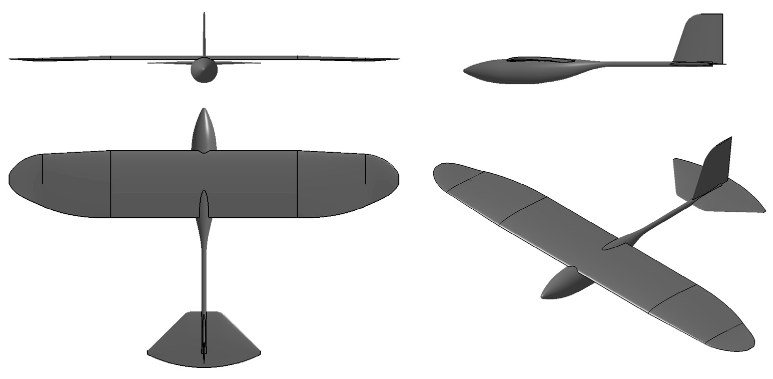
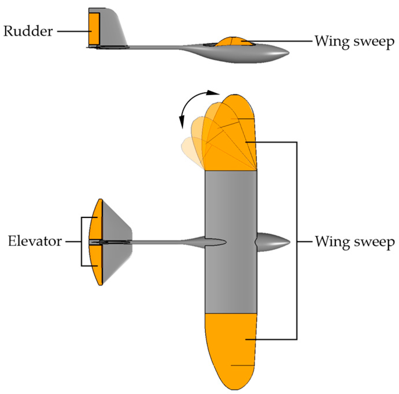
2.1. Overall Layout and Parameters

The research object of this article is a soaring drone, which is an unpowered fixed-wing drone that mimics soaring birds that use thermal updrafts to soar. During the process of soaring, birds keep their wings locked and do not flap them. They change their flight trajectory and maintain flight balance by swiping their wings and twisting their tails. By asymmetric wing sweeping, the wing load can be changed during flight, and different wing loads can adapt to a wider range of updrafts. The layout of the soaring drone used in this study is mainly modeled after soaring birds. The wings adopt the form of asymmetric swept wings and have a large area to reduce wing load. The tail adopts the conventional tail form of fixed-wing drones. Therefore, the control surfaces of this soaring drone differ from those of a conventional fixed-wing drone. This drone does not have ailerons but achieves their control effect through the asymmetric sweep of the wing on one side.
The basic parameters of the soaring drone are provided in Table 1. Its overall schematic diagram is shown in Figure 1, and its three control surfaces are shown in Figure 2.
The asymmetric sweep of wings results in unequal wing areas on the two sides of the drone, resulting in unequal lift and roll torques and achieving functions similar to those of ailerons. The main flight state of the drone in this article is to use a thermal updraft to soar, and the state in which both wings sweep back at the same time is the attitude adopted by birds to improve speed and maneuverability. This attitude is not necessary for the drone in this article. Therefore, only one wing on one side, either left or right, is swept back in this study without considering the situation in which both wings are simultaneously swept back. The maximum sweep angle of the wing is 60°.

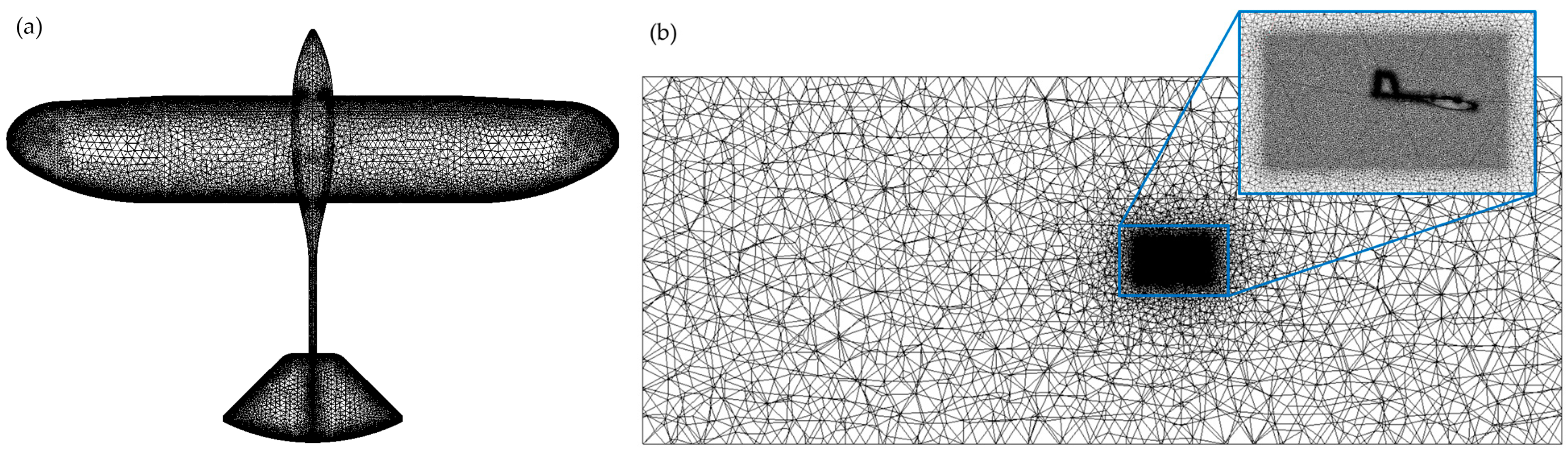
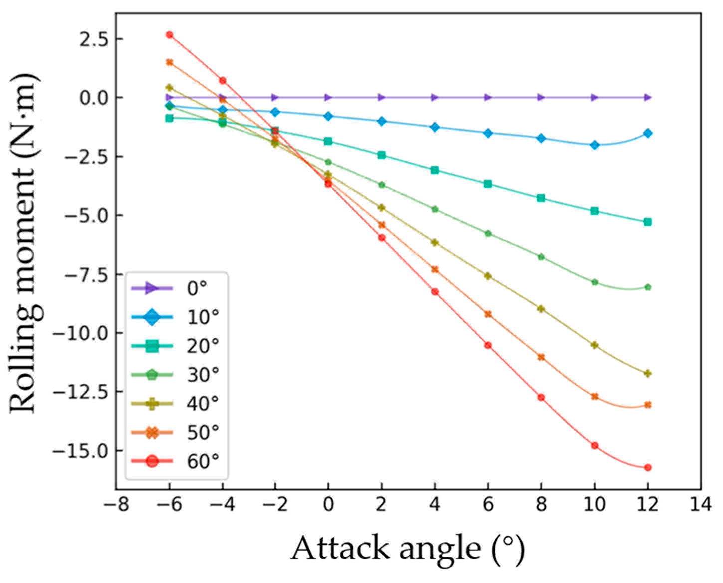
2.2. Aerodynamic Data

In this paper, the aerodynamic data required are obtained through the computational fluid dynamics (CFD) method, and ANSYS Fluent (version Ansys 2022 R1) is used for aerodynamic simulation calculations. The calculation model adopts the k-omega (SST) method. A model with an unstructured mesh form and approximately 19 million grids is used for simulation calculations, as shown in Figure 3. In areas with larger curvature on the surface of the drone, such as the leading edges of the wings and tail, the grid is denser. The Reynolds number of the soaring drone in this article is approximately 4 × 10⁵. In the boundary layer mesh setting, the thickness of the first layer is 1 × 10⁻⁴. When calculated in Fluent, it can be found that the y+ values on the wing areas are all less than 5, mainly between 1 and 2.
The entire flow domain is a cuboid with a cross-section square of 20 m × 20 m and a length of 50 m. The drone is located 20 m from the inlet and 30 m from the outlet. A denser mesh domain has been added near the drone. The denser mesh domain is a cuboid with a cross-section of 3.5 m × 2 m and a length of 3.7 m.
The convergence conditions are mainly set for the residuals of some parameters. The energy residual needs to be below 10−6, and the residuals of other variables need to be below 10−3. In addition, the velocities in the x, y, and z directions need to reach stability.
To state the feasibility of using wing sweep instead of ailerons, the variation in the rolling moment with the angle of attack for a single side sweep of 0~60° is shown in Figure 4 (taking the left wing sweep as an example, the right roll of the drone is positive). Figure 4 shows that at the same angle of attack, as the left wing sweep increases, the rolling moment of the drone to the left also increases. The greater the sweep of the left wing is, the smaller the area of the left wing, the greater the difference with the area of the right wing, the greater the lift difference, and the greater the left rolling moment. Therefore, the asymmetric sweep of wings can replace ailerons.

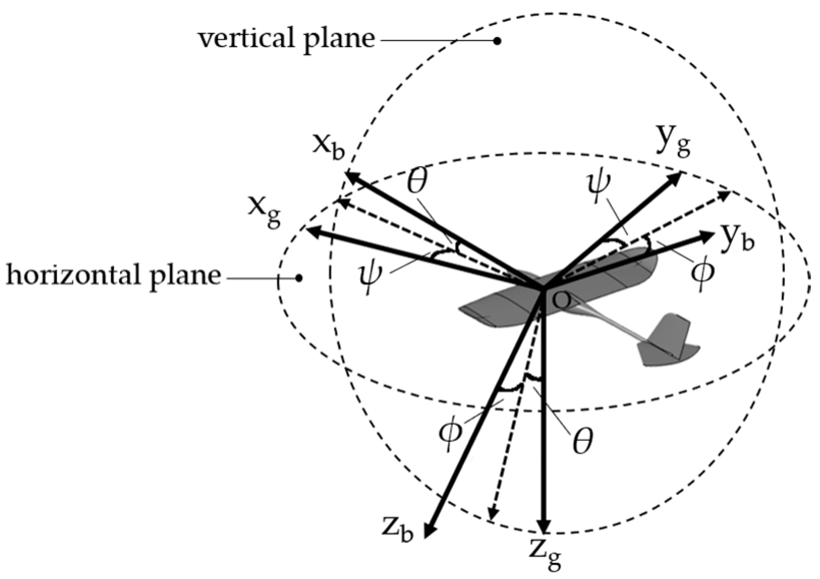
2.3. Flight Dynamics Model

The drone in this study is an asymmetric unpowered drone; the body axis coordinate system of the drone is established in Figure 5. Oxgygzg is the ground coordinate system, and Oxbybzb is the body axis coordinate system.
The six-degree-of-freedom flight mechanics model equations system in the body axis system and the kinematic equations between Euler angles and angular velocities are as follows:
{ X m g sin θ = m ( u ˙ + q w r v ) Y + m g cos θ sin ϕ = m ( v ˙ + r u p w ) Z + m g cos θ cos ϕ = m ( w ˙ + p v q u ) L = I x p ˙ + ( I z I y ) q r + I y z ( r 2 q 2 ) + I x y ( r p q ˙ ) I z x ( p q + r ˙ ) M = I y q ˙ + ( I x I z ) p r + I z z ( p 2 r 2 ) + I y z ( p q r ˙ ) I x y ( q r + p ˙ ) N = I z r ˙ + ( I y I x ) p q + I x y ( q 2 p 2 ) + I z z ( q r p ˙ ) I y z ( r p + q ˙ )
ϕ ˙ = p + q sin ϕ tan θ + r cos ϕ tan θ θ ˙ = q cos ϕ r sin ϕ ψ ˙ = sec θ q sin ϕ + r cos ϕ
In the equations, X, Y, and Z represent the projections of the aerodynamic forces acting on the drone in the three directions in the body axis system; L, M, and N are the projections of the combined torque of the drone in the three directions in the body axis system; m is the mass of the drone; I x , I y , and I z are the moments of inertia about the three axes in the body axis system; I x y , I y z , and I z x are the inertia products of the drone for the three planes in the body axis system; u, v, and w represent the velocity components of the drone in the three directions in the body axis system; p, q, and r are the rotational speeds of the drone about the three axes in the axis system; θ is the pitch angle of the drone; ϕ is the roll angle of the drone; and ψ is the yaw angle of the drone.
The flight mechanics model of the drone in this article differs from that of conventional symmetric drones. Due to the lack of power for the soaring drone, there is no thrust in the force acting on the drone and no momentum change caused by the engine rotor in the torque calculation formula.
More importantly, for symmetric drones, the inertia products I x y and I y z are zero. In this study, the rotational inertia and inertia products of the drone during flight vary due to the asymmetric sweep of the wings. During flight, the rotational inertia and inertia products are not constants but vary with the asymmetric sweep angle of the wing, which results in nonlinear and coupled dynamics in control.

3. Study Objective of Soaring Drone Control

The objective of this study is to control the drone to follow the guidance of the soaring strategy, that is, to control the drone to follow the trajectory of the continuously updated flight strategy by manipulating the control surfaces. Soaring is unpowered gliding that utilizes vertical winds in thermal updraft. The soaring strategy can be mainly divided into two stages: exploring updrafts and utilizing updrafts. The trajectory during the exploration is random and irregular, while the trajectory during the utilization is mainly spiral. The soaring strategy determines the horizontal direction of the drone’s flight based on the vertical wind situation, without the need for active control of vertical movement of the drone. Consequently, the drone, which is tasked with following the soaring strategy, only needs to track the horizontal trajectory. Due to the fact that the soaring strategy is constantly updated based on environmental information, the target position at the next moment is determined by the current state. Therefore, when the drone is following a soaring strategy, it is essentially tracking a moving target, and the trajectory of the moving target can be regarded as some random curves.
Moving target tracking requires a guidance method. The guidance process in this study is formulated as follows: Starting from the current position of the drone, a circular arc is drawn in the horizontal velocity direction as the tangent direction. The size of the arc is controlled so that the arc can pass through the current position of the moving target, and the radius of the circular arc is the current target flight radius for the drone. Every certain time step, an arc is drawn based on the relative position between the drone and the target. The drone flies according to the target radius, ultimately achieving the moving target tracking mission.
Figure 6 shows the guidance principle, with arrows indicating the horizontal velocity directions of the drone and moving target, representing the current moment, the moment after a certain time step, the target flight radius calculated based on the relative position between the drone and the target at time, and the target flight radius at the next moment.
Based on the above information, it is clear that we only need to train the control agent to have the ability to turn at different radii and combine it with the circular arc guidance method, and we can achieve horizontal trajectory tracking of moving targets. The essence of tracking the soaring strategy is to track the horizontal trajectory, which means that the control problem of the soaring drone in soaring tasks can be solved.

4. Control Agent Training

Due to the nonlinear and coupled dynamics problems caused by the asymmetric control surface of the soaring drone in this article, dynamic balancing through unconventional control surfaces is very complex. Reinforcement learning is very suitable for solving such problems. Reinforcement learning is an important method for studying complex strategies and control, and it is also an important means of achieving the intelligent autonomous control of drones.
As described in the study objective, the primary control objective is to maneuver the turning flight of the drone through the utilization of its control surfaces. In actual flight tasks, guidance methods can be combined to achieve horizontal trajectory tracking of a moving target. Reinforcement learning is suitable for solving this kind of end-to-end black box problems. In summary, this article adopts reinforcement learning to study the control problem of the soaring drone, and the training of control agent focuses on turning flight at different radii.
The control and simulation process of the drone in this article is shown in Figure 7.
The reinforcement learning algorithm used in this study is the SAC algorithm, which can effectively solve continuity control tasks. The SAC algorithm combines the actor-critic method with the concept of entropy in reinforcement learning and introduces techniques such as entropy optimization and adaptive temperature parameters to adapt to more complex tasks. The performance of the algorithm has been improved by introducing dual networks and soft updates. The SAC algorithm maximizes the expected return while maximizing the entropy of the strategy, making the agent more random in executing actions, thereby improving the agent’s exploration ability and adapting to more complex environments.
The essence of reinforcement learning is to train an agent to decide actions based on the observed environment and its own state and then move on to the next state until the set task is completed. Agent training is a process of continuous interaction between the initial agent and the simulation environment, self-optimization based on the interaction results, and ultimately maximization of the set rewards. The settings of the input state space, output action space, and reward function are three key components. It is necessary to analyze and compare the reinforcement learning settings in order to achieve satisfactory training results.

4.1. Hyperparameters and Neural Network Settings for Reinforcement Learning

To train the reinforcement learning algorithm, the reward discount rate, soft update parameter, maximum capacity of experience buffer, batch size, neural network learning rate, and other parameters are considered.
In this paper, the reward discount rate is set to 0.99. The closer this parameter is to one, the more emphasis is placed on long-term rewards. The training in this paper is based on continuous trajectory control, so we place more emphasis on long-term rewards. The soft update parameter is set to 0.005. This parameter represents the speed of the parameter updates for the neural network. The value range of the soft update parameter is (0,1]. The closer this value is to zero, the slower the parameter updates are for the neural network. The training may tend to be more stable, but the convergence time increases. In this training, the flight radius for each round of training is random, and there are significant changes in flight control; thus, smaller soft update parameters are adopted to reduce the risk of oscillation and divergence during updates.
In reinforcement learning, the experience required for training is generated by the continuous interaction between the agent and the environment. The generated experience needs to be stored in the experience buffer, which is set to a capacity of 100,000 in this article. For each optimization, a certain number of experience bars must be randomly selected from the experience buffer for the agent to learn, and this number is called batch size. In this article, the batch size is set to 512.
The SAC algorithm includes three kinds of networks: strategic neural networks, action value neural networks, and state value neural networks. The strategic neural network is the agent neural network that inputs states and outputs actions. The input of the action value neural network is the state and action, and the output is a numerical value used to evaluate the performance of the action under this state. The input of the state value neural network is the state, and the output is a numerical value used to evaluate the performance of the achieved state. The neural networks all use four hidden layers, with 256 neurons in each hidden layer. They all have their own neural network learning rate. The learning rate of a neural network is equivalent to the update step size. A small learning rate requires many updates before convergence is reached. A learning rate that is too large causes drastic updates that lead to divergent behavior. Based on experience, we set the learning rates of the action value neural network and state value neural network as 1 × 10⁻⁴ and the learning rate of the strategic neural network as 1 × 10⁻⁵. The key settings and parameters can refer to Table 2.

4.2. Training Environment

The training and testing of agents cannot be separated from the simulation environment. The agent interacts with the simulation environment, gains experience, and updates its parameters on the basis of experience. The drone flight dynamics model in the second part is the core of the simulation environment. By inputting the actions of the control surfaces, the drone attitude, speed, position, and other flight state parameters at the next moment can be calculated. The agent outputs actions based on the new state. With continuous looping, many flight experiences and a complete flight trajectory are obtained. The action space, state space, and reward function are the key factors that influence the effectiveness of agent training.

4.2.1. Action Space

In terms of the action space, the soaring drone in this study has three types of control surfaces, namely, an elevator, a rudder, and a wing sweep. The sweep of the left wing is set as positive, and the range of action for the wing sweep is −60°~60°. When the action input is −60°, this represents a sweep of 0° for the left wing and 60° for the right wing. The deflection ranges of the elevator and rudder are −45°~45°. The downward deviation of the elevator is positive, and the left deviation of the rudder is positive. To make the action more continuous and refer to the efficiency of the servo, the actions in this study do not refer to the control surface deflection angle but rather to the amount of control surface deflection change.

4.2.2. State Space

In terms of the state space, complete state information must be input to the agent so that it can determine appropriate actions based on the state, but the elimination of redundant and interfering information as much as possible is also necessary. The state parameters of the drone mainly include the position, velocity, attitude angle, attitude angular velocity, aerodynamic angle, and control surface deviation angle. The main task of the flight control agent in this study is to track the moving target, and the training content is drone flights with different turning radii. The state input is the basis on which the drone decides control surface action commands. Through analysis, the absolute position of the drone can be concluded to not affect its actions, as under a constant turning radius, the drone will not change its control surfaces regardless of where it hovers. The control is related to the turning radius and not to the absolute position of the drone. Therefore, theoretically, the flight radius is an important input. With only the flight radius for an input, the drone is in an open-loop state in terms of position information, and without feedback, position errors may accumulate, leading to flight deviation from the target trajectory. Therefore, in this study, the distance between the drone and the hovering center is subtracted from the target radius, and the difference is used as an input for determining the position error, providing error feedback for the drone so that the drone can adjust its position based on the error. The definition of the position error is shown in Figure 8.
The airspeed and aerodynamic angles of the drone, including the angle of attack and sideslip angle, significantly influence its dynamic pressure and the force acting on it. Thus, the sensing of these metrics by the drone is crucial. During flight, there are limitations on the drone attitude angle to prevent instability. Consequently, the pitch angle, the roll angle, and their respective angular velocities should be utilized as state inputs, enabling the agent to comprehend its current attitude and refrain from issuing commands that could exacerbate instability. In the case of the yaw angle, its information during hovering is less valuable. Similar to the absolute position, in the same initial state, the drone does not change its control surfaces, regardless of which direction it turns in. However, different yaw rates can influence the aerodynamic angle and subsequent force, thus playing a role in determining actions. Furthermore, the deflection angles of the control surfaces should also be incorporated as state inputs. As the actions in this study correspond to changes in the control surfaces, the current position of these surfaces serves as a crucial basis for determining any increase or decrease in their deflection. In summary, the state space is initially set as the flight target radius, distance error, airspeed, pitch angle, roll angle, pitch angular velocity, roll angular velocity, yaw angular velocity, angle of attack, sideslip angle, wing sweep angle, elevator deflection angle, and rudder deflection angle.
However, there is a possibility of information redundancy in the flight target radius and position error. Therefore, comparative training is conducted in this study to determine which factor should be retained in the state space, and the three kinds of state spaces are shown in Table 3.
Figure 9 shows the variation curves of the flight time and reward with the number of training rounds. Reward refers to the evaluation criteria for the performance of agents in completing tasks during the training process. The specific settings and comparative analysis will be explained in detail later. Here, it is only used to distinguish the advantages and disadvantages of different state inputs. The dark gray curve represents the training with the position error, while the dark cyan curve represents the training with the target radius. The orchid curve corresponds to the training with the position error and target radius. The darker curves are the smoothed results of the corresponding lighter curves.
According to the training process shown in Figure 9, it is difficult to obtain a successful agent when trained with the target radius. The agent when trained with the position error can learn flight control faster, approximately 10,000 rounds earlier than the agent trained with the position error and target radius. The training results in terms of the flight time and reward of the agent when trained with the position error are better, indicating that the input of the radius does not bring about better training effects but instead brings about redundancy, resulting in lower rewards and slower training speed. Therefore, the flight target radius is removed from the state inputs in this study.

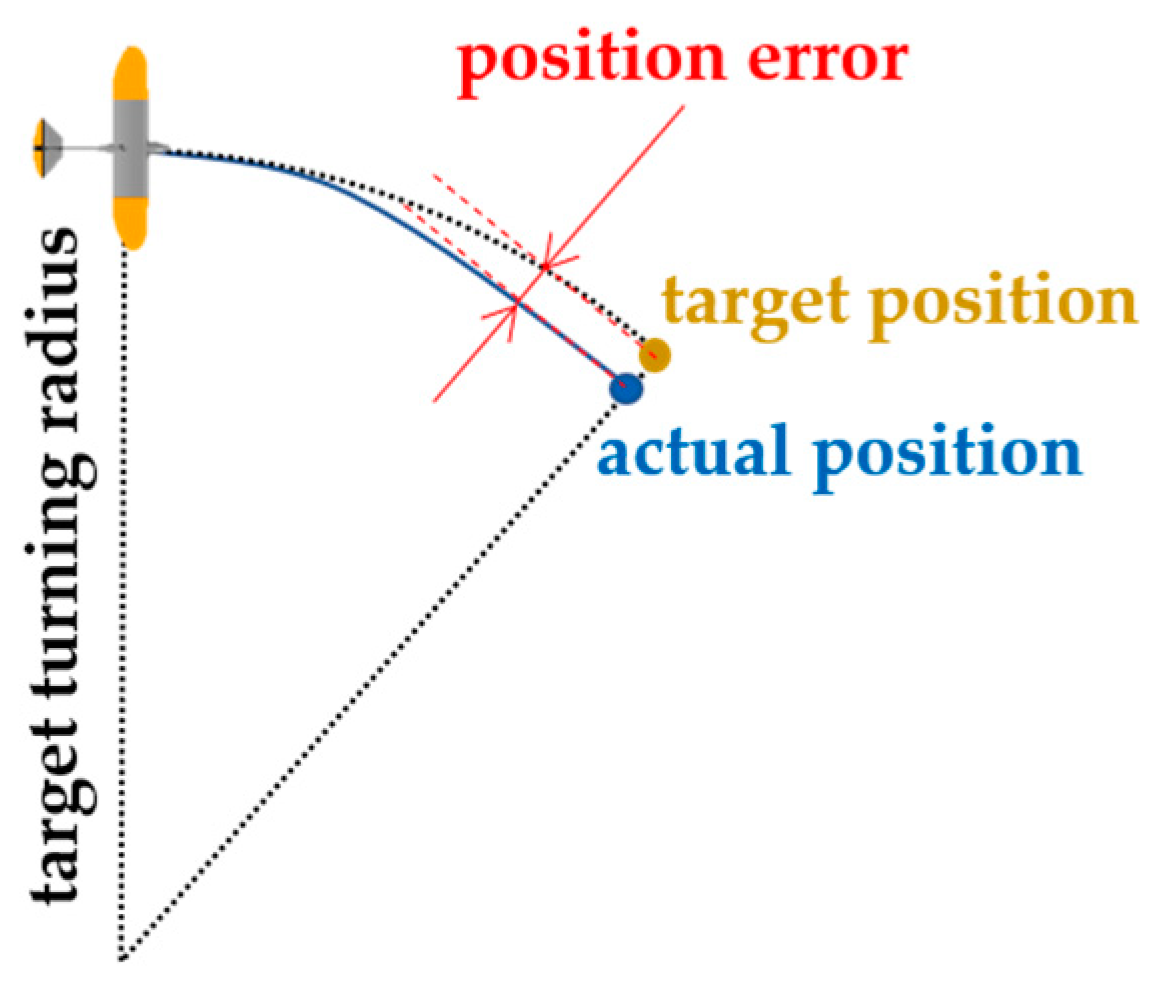
4.2.3. Reward Function

The reward function serves as a pivotal factor that directs the updating and optimization of agents. It should not only encapsulate an objective assessment of the quality of the flight conditions but also refrain from excessive subjective influence. The reward function comprises both the step reward and episode reward. The step reward refers to the reward obtained by the drone at each time step, the episode reward refers to the reward obtained after a full flight is completed, and the final reward is the sum of the accumulated step and episode rewards.
The primary training objective for agents is to execute turning flights with various radii, and the position error in the states is a key evaluation metric for judging the quality of mission completion. Consequently, the position error is incorporated into the step reward.
Moreover, to ensure that the drone soaring flight maintains a low and consistent descent speed, speed-related metrics are appended to the reward to guarantee that the drone flight velocity and angle of attack remain within acceptable limits. Another important reward factor is the flight time. A constant term should be added to each step reward as a reward for the flight time.
For the episode reward, in this study, the termination condition of the training episode is set as the occurrence of an unstable attitude or drone landing. Because the drone performs unpowered soaring flights, its altitude will constantly decrease, so the flight episode is terminated when the altitude falls below 3 m. Additionally, during flight, if the attitude angle or aerodynamic angle of the drone exceeds the normal range, this can lead to loss of control. Therefore, the flight episode is also terminated when either the attitude angle or the aerodynamic angle exceeds the normal range. These two termination conditions are undesirable, and thus, a significant negative reward is provided to the agent upon episode termination.
In summary, the reward function adopted in this paper is as follows:
r e w a r d = 3000 ,   temination 10 p _ d e v + r e w a r d _ v v + r e w a r d _ v h ,   else r e w a r d _ v v = + 3 ,   v v 1.5   m / s 3 ,   v v > 1.5   m / s r e w a r d _ v h = + 3 ,   14 v h 16.5   m / s 3 ,   e l s e
In Equation (3), termination indicates the termination of an episode, resulting in a reward of −3000. In other cases, the agent receives a step reward. The constant 10 in the step reward represents the reward for the flight time. | p _ d e v | denotes the absolute value of the difference between the distance of the drone’s current position from the hovering center and the target flight radius. The greater the distance deviation is, the greater the negative reward the agent receives. r e w a r d _ v v and r e w a r d _ v h represent the rewards for the vertical and horizontal velocities, respectively. If the velocity is within a reasonable range, then the agent receives a reward of +3. Otherwise, a reward of −3 is given.
The proportion of various factors in the reward function also affects the updating and optimization direction of the agent, with a greater proportion indicating that the agent will prioritize satisfying that factor. In the setup of the step reward, the position error reward is nonpositive, the flight velocity rewards can be either positive or negative, and the flight time reward is positive. Adjustment of the reward values of each factor to an appropriate weight is crucial, as is ensuring that the overall step reward is positive; otherwise, poor training effectiveness will be obtained. To explore this topic, three different reward functions are compared in this article: the reward function with more emphasis on the position error (Equation (4)), the reward function with more emphasis on the flight time (Equation (5)), and the reward function with appropriate weights (Equation (6)).
r e w a r d = 3000 ,   termination 10 1000 · p _ d e v + r e w a r d _ v v + r e w a r d _ v h ,   else
r e w a r d = 3000 ,   termination 1000 p _ d e v + r e w a r d _ v v + r e w a r d _ v h ,   else
r e w a r d = 3000 ,   termination 10 p _ d e v + r e w a r d _ v v + r e w a r d _ v h ,   else
The flight time variation curves of the training processes using the three reward functions with the round number are shown in Figure 10. The gray curve represents the training process focusing on the flight time, while the cyan curve corresponds to the training process emphasizing the position error. The orchid curve depicts the training process with balanced rewards. The darker curves are the smoothed results of the corresponding lighter curves.
According to the training results, it can be seen that the training effect of balanced rewards was the best. the agent achieved the maximum simulation time for the flight duration more quickly and stably.
When the flight time reward weight was significant, the agent prioritized extending the flight duration. As was evident from the training process, the flight time of training that focuses on time increases first.
Training that focused on the position error did not yield the expected results. During the training process, when the position error reward weight was relatively high, the step reward was mostly negative in most cases, resulting in a smaller accumulation of rewards with an increased number of steps, making optimization by the agent difficult. This result indicates that a positive step reward is preferable because it provides positive guidance for the agent; otherwise, the agent update and optimization become difficult.
Due to the different reward functions, a direct comparison of the rewards during the training process is not feasible. Therefore, in this study, the agents with the reward function that emphasizes the flight time and the balanced reward function are tested. The cumulative position error is calculated, and the flight trajectories under a target flight radius of 500 m are compared, as shown in Figure 11.
In the tests, 1500 steps each were simulated for both agents. At each time step, there was an error between the drone and the target position. The average position error of the agent’s flight trajectory under balanced rewards was about 0.33 m. The average position error of the agent’s flight trajectory under a stronger emphasis on the flight time was about 1.48 m. Furthermore, according to the test results in Figure 11, the flight trajectory of the agent under balanced rewards is smoother, whereas when the reward function prioritizes the flight time, the flight trajectory presents a polygonal state and the agent exhibits faster flight patterns. This result underscores the rationale and effectiveness of the balanced reward function adopted in this study.
In summary, the action space, state space, and reward functions in the reinforcement learning environment are shown in Table 4.
In the training environment in this study, the initial state of the drone is that it is thrown in the positive x-axis direction at a speed of 20 m/s from a height of 500 m. Two agents—counterclockwise turning and clockwise turning—with a turning radius range of 200~3000 m are trained in this study. The target flight radius for each training round is random. The soaring strategy mentioned in this study is learned based on the soaring of large birds such as eagles and vultures. They have a large hovering radius during soaring flight and generally use a thermal updraft radius of over 200 m. Therefore, the minimum turning radius for the training drone in this study is selected as 200 m.

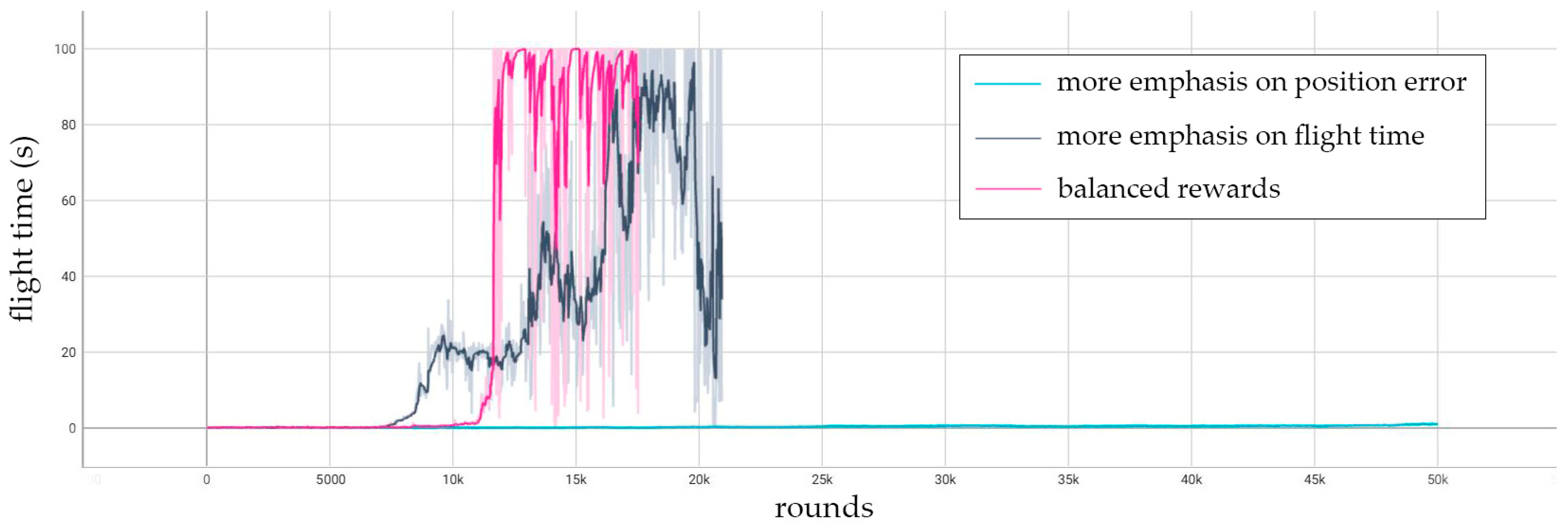
4.3. Training Result

Because the target flight radius in every training round is random, the algorithm cannot completely converge with limited training rounds and computational power. In response to this issue, a high-reward agent screening method is adopted in this study. Once the number of training rounds exceeded 10,000 iterations, agents exhibiting higher rewards were preserved during the training process. These agents with high rewards will be tested, and we selected agents that can stably and accurately control the drone turning at various target radii. After screening, two control agents that met the requirements are selected, and their respective test outcomes are presented in Figure 12, which provides an overhead view of multiple flight trajectories. The black dot represents the initial position of the drone, the blue curves represent the flight trajectories for different target radii, and the numbers on the curves represent the target flight radius. The target radius range during the training process was 200~3000 m, but during testing, the agent could also complete control missions when the target radius is greater than 3000 m, indicating that the agent had a certain degree of generalizability.
Taking a clockwise turn with a radius of 500 m and a simulation time of 30 s as an example, the variation curves of the heading angle, roll angle, and three control surfaces over time are outputted as shown in Figure 13. The initial state of the drone is a straight flight, and under the control of the agent, it enters a turning flight. After the drone enters a stable turning state, the yaw angle continues to uniformly increase, and the roll angle remains stable at a right roll angle of 5.35°, which is consistent with the attitude characteristics of the drone during right turning. After adjustment of the control surfaces, the final trim conditions are as follows: the elevator deflects upward by 6.4°, the wing on the right side has a sweepback of 2.52°, and the rudder deflects to the left by 4.59°.
To test the control performance and accuracy of the agent, 10,000 tests were conducted, with a simulation time of 100 s for each test. The agent used for tests was selected from high-reward agents. It could achieve stable and accurate control. In 10,000 tests, the agent completed all of the turning flights with the target radii. The target flight radius for each test was randomly selected from a range of 200~5000 m. The accumulated position error was recorded and statistically analyzed, as shown in Figure 14. Regarding the position error accumulation, each test spanned 100 s, with a simulation time step of 0.1 s. Consequently, a single test round comprised 1000 steps, and the accumulated position error was the sum of 1000 errors. According to the statistical results, the average position error of the drone under the control of the agent was less than 0.6 m at each moment. In most rounds, the average position error was approximately 0.33 m, and the number of rounds with an error between 0.2 m and 0.45 m accounted for approximately 95%.
The distribution of the error percentage compared with the target flight radii is shown in Figure 15. The maximum drone position error percentage relative to the target flight radius was 1.8‰. In 98.95% of the test rounds, the relative position error percentage at each moment was below 1‰, and in 92.22% of the test rounds, this error percentage stays below 0.5‰, indicating that the control agent can achieve good results and accuracy.

5. Trajectories Tracking Simulation

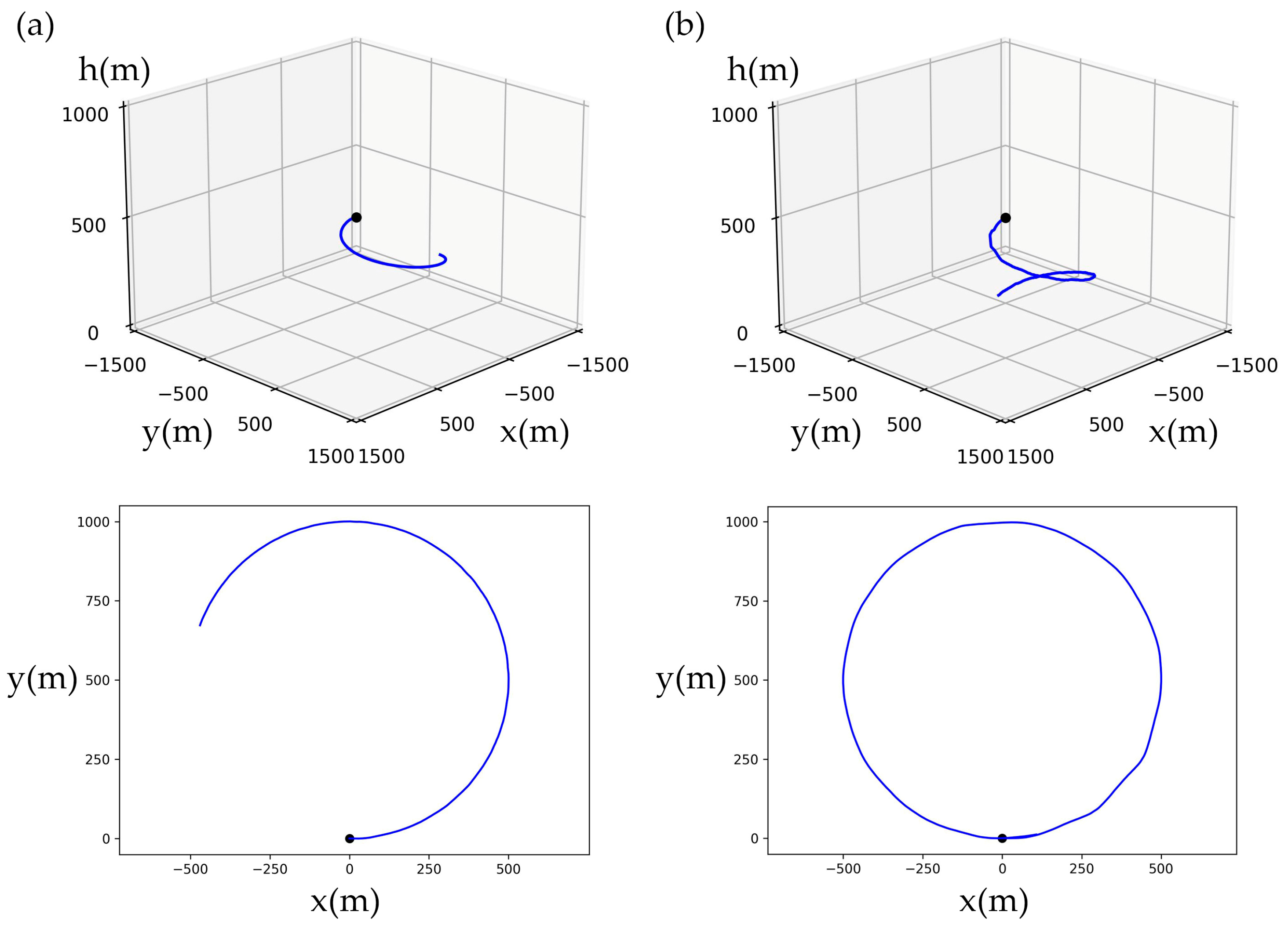
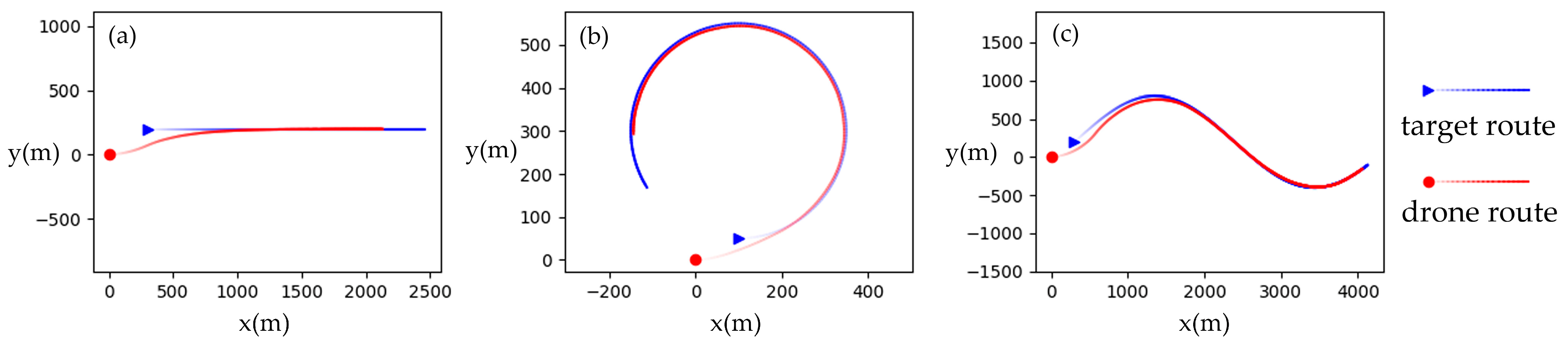
5.1. Basic Trajectories Tracking

To verify the effectiveness of the control agent and guidance method, three typical tracking trajectories are tested, namely, straight, circular, and sinusoidal curves. The results are shown in Figure 16. The red dots represent the initial position of the drone, while the blue triangle represents the initial position of the target. The red lines represent the trajectory of the drone, and the blue lines represent the trajectory of the target. The gradually darker color of the trajectories represents the motion with the passage of time. Figure 17 shows the three-dimensional situation of the tracking process, with the red curve representing the drone trajectory and the blue dotted line representing the target horizontal trajectory.
There are gusts of wind in the natural environment, which are a phenomenon where the wind speed in a certain direction increases instantly and then quickly disappears. This article discusses the ability of drones to resist gusts of wind. The purpose of the soaring drone control in this article is to track horizontal trajectories, so gust interference is mainly applied in the horizontal direction. By observing whether the drone can return to its original tracking trajectory after gust interference, we analyze the ability of the control agent to resist gusts of wind.
Taking the straight-line flight of drones as an example, it is convenient to observe the impact of gusts on flight control trajectories. The gust setting in this article is that a horizontal wind speed suddenly occurs from a certain direction and lasts for one minute before disappearing. Based on the heading direction, gusts blow towards the drone in various directions, and the impact of gusts in different directions on the drone’s flight control trajectory is shown in Figure 18. From the results, it can be seen that: (a) when the direction of the gust is opposite to the heading angle, the drone does not deviate from the horizontal trajectory, but due to the stable airspeed control, the ground speed slows down and the horizontal distance from the target increases; (b) when the direction of the gust is the same as the heading angle, the ground speed increases and the horizontal distance to the target decreases; (c) (d) (e) when there is a certain angle between the direction of the gust and the heading, the drone deviates from the trajectory but eventually adjusts back.
Due to the limitations of drone flight performance, gusts exceeding a certain speed can cause the drone to be unable to adjust back to a stable state. Horizontal gusts can change the angle of attack and sideslip. If the angle of attack or sideslip angle is too large, it can cause the drone to stall and become uncontrollable. This article adds gusts in eight directions, respectively, and continuously increases the wind speed until the drone cannot adjust back to a stable state, obtaining the maximum gusts that the drone can withstand in each direction. The maximum gusts that the drone can withstand in each direction are shown in Figure 19.

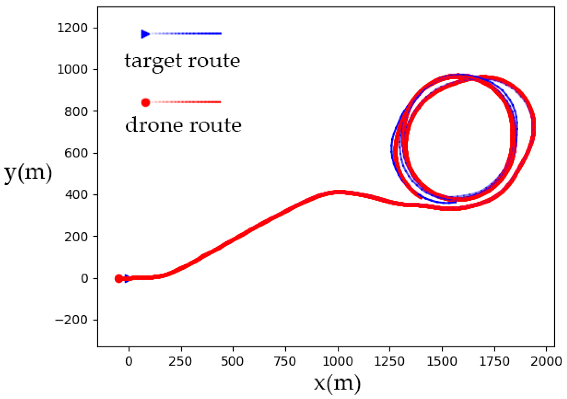
5.2. Soaring Trajectory Tracking

The agent can control the drone to track the moving target in various trajectory forms. The object of this study is a soaring drone, whose ultimate mission is to search for a target and utilize thermal updrafts for unpowered soaring under flight strategies. To further verify the generality of the agent in moving target tracking, soaring flight mission simulations in combination with soaring flight strategies are conducted. The soaring strategy determines which direction the drone should fly in based on environmental parameters, and the agent can autonomously control the drone to fly to the target position provided by the strategy. This approach is essentially the same as the moving target tracking simulated earlier. The simulation results of the soaring mission are shown in Figure 20 and Figure 21. The red dots in Figure 20 represent the starting point of the soaring drone, and the red curves represent the flight trajectory. The blue dotted lines on the plane represent the target trajectory calculated by the soaring strategy. The black concentric circles are the locations of the thermal updrafts in the simulation environment. The center of the concentric circles is the center of the updrafts, and the vertical wind speed gradually decreases radially outward from the center. The soaring strategy guides the drone into an updraft, and it hovers around the center, using the updraft for unpowered climbs, similar to soaring birds. Figure 21 shows the horizontal strategy trajectory and the drone trajectory.
The simulation results show that the agent can provide end-to-end control of the drone from the control surfaces to the trajectory, achieve moving target tracking, and complete the soaring mission.

6. Conclusions

Based on the research, we obtained the following conclusions:
  • The control agent of the soaring drone with asymmetric swept wings was obtained through reinforcement learning in this article. The agent can directly output control surface commands, including the wing sweep, elevator, and rudder, based on the position error and its own states, thereby controlling the drone to fly with the target radius. This also indicates that the asymmetric sweep of the soaring drone wings can achieve roll control like ailerons. By combining turning control and arc guidance methods, the agent can control the unpowered soaring drone, which utilizes asymmetric deformation control surfaces, to achieve horizontal tracking of moving targets. Ultimately, the drone can be controlled to track the trajectory of the soaring strategy.
  • In the study of using reinforcement learning for drone control, the setting of the state space and reward function is the key factor affecting the training results.
    In terms of setting the state space, it is necessary to analyze the necessity of the input state variables and eliminate those that cause information redundancy. The target radius and position error mentioned in this article may both seem necessary, but upon comparison, it was found that there is information redundancy and that the position error is more important.
    In terms of setting the reward function, the duration of stable control is an essential reward factor. The remaining reward factors depend on the control task. The weight of each reward factor must be adjusted, and a positive step reward must be maintained.
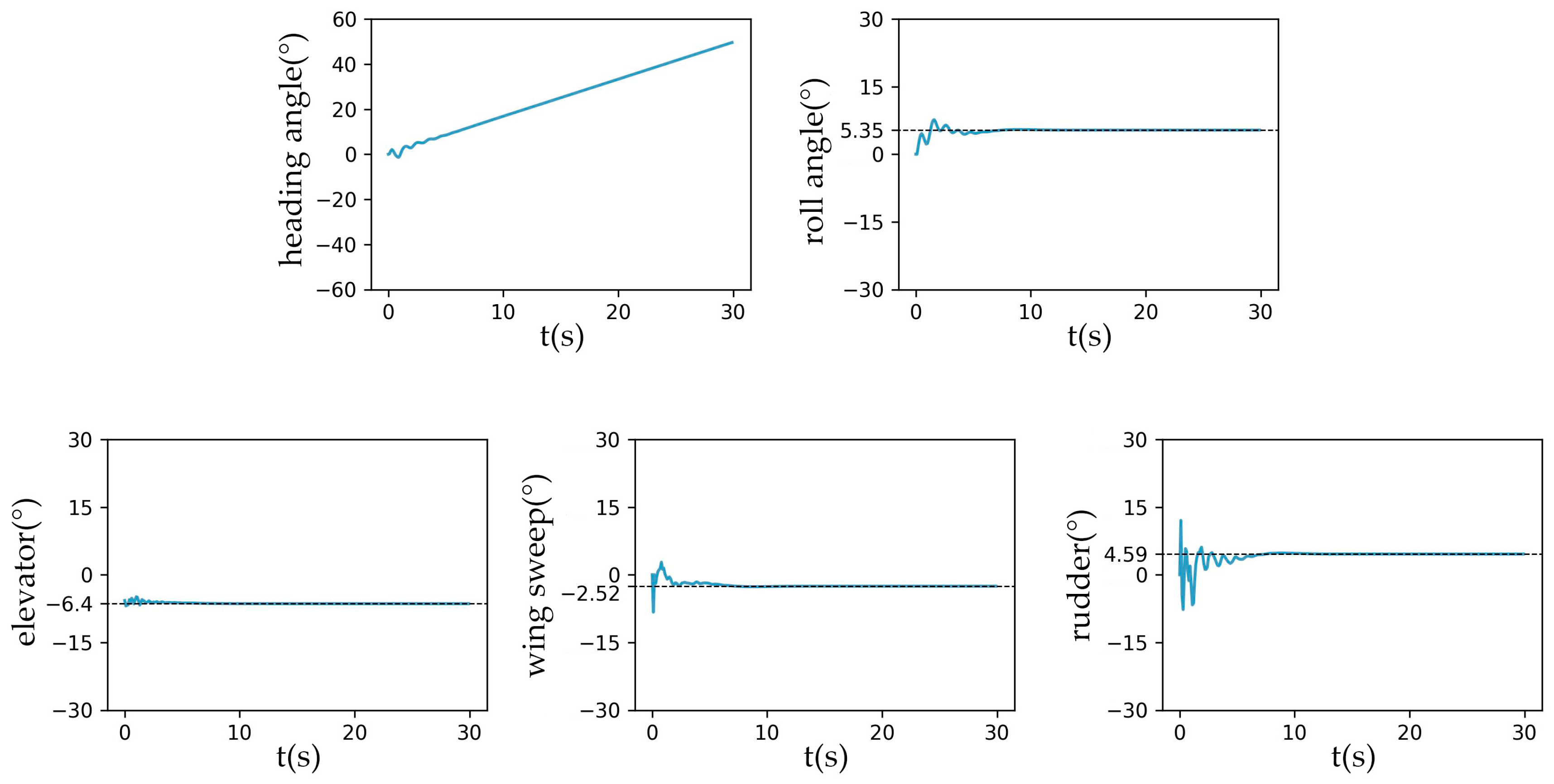
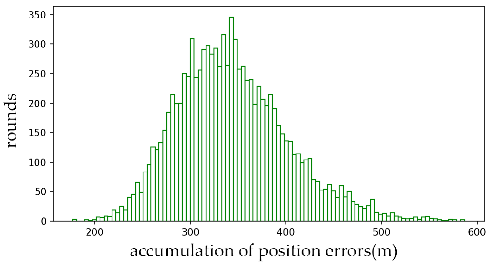
  • The trained agent can control the soaring drone to perform accurate turning flights. It can complete counterclockwise and clockwise turns with a turning radius of more than 200 m. In extensive testing, the average position error is less than 0.6 m, concentrated around 0.33 m. The maximum drone position error percentage relative to the target flight radius is 1.8‰. In 98.95% of the test rounds, the relative position error percentage at each moment is below 1‰.

Author Contributions

Conceptualization, Y.C., D.Y. and Z.W.; methodology, Y.C.; software, Y.C.; validation, Y.C., D.Y. and Z.W.; formal analysis, Y.C., D.Y. and Z.W.; investigation, Y.C. and D.Y.; resources, Z.W.; data curation, Y.C.; writing—original draft preparation, Y.C.; writing—review and editing, D.Y. and Z.W.; visualization, Y.C.; supervision, D.Y. and Z.W.; project administration, D.Y. and Z.W.; funding acquisition, Z.W. All authors have read and agreed to the published version of the manuscript.

Funding

This research was funded by the National Key Research and Development Program of China (2023YFB3905701).

Data Availability Statement

The original contributions presented in the study are included in the article, further inquiries can be directed to the corresponding author.

Conflicts of Interest

The authors declare no conflicts of interest.

References

  1. Mohammed, S.T.; Kastouri, M.; Niederfahrenhorst, A.; Ascheid, G. Video Representation Learning for Decoupled Deep Reinforcement Learning Applied to Autonomous Driving. In Proceedings of the 2023 IEEE/SICE International Symposium on System Integration (SII), Atlanta, GA, USA, 17–20 January 2023; pp. 1–6. [Google Scholar] [CrossRef]
  2. Yu, X.; Fan, Y.; Xu, S.; Ou, L. A self-adaptive SAC-PID control approach based on reinforcement learning for mobile robots. Int. J. Robust Nonlinear Control. 2022, 32, 9625–9643. [Google Scholar] [CrossRef]
  3. Mcgrath, T.; Kapishnikov, A.; Tomaev, N.; Pearce, A.; Hassabis, D.; Kim, B.; Paquet, U.; Kramnik, V. Acquisition of Chess Knowledge in AlphaZero. arXiv 2021, arXiv:2111.09259. [Google Scholar] [CrossRef] [PubMed]
  4. Idrissi, M.; Salami, M.; Annaz, F. A Review of Quadrotor Unmanned Aerial Vehicles: Applications, Architectural Design and Control Algorithms. J. Intell. Robot. Syst. 2022, 104, 22. [Google Scholar] [CrossRef]
  5. Ang, K.H.; Chong, G.; Li, Y. PID Control System Analysis, Design, and Technology. IEEE Trans. Control. Syst. Technol. 2005, 13, 559–576. [Google Scholar]
  6. Hu, Y.; Yan, H.; Zhang, H.; Wang, M.; Zeng, L. Robust Adaptive Fixed-Time Sliding-Mode Control for Uncertain Robotic Systems with Input Saturation. IEEE Trans. Cybern. 2023, 53, 2636–2646. [Google Scholar] [CrossRef] [PubMed]
  7. Hegde, N.T.; George, V.I.; Nayak, C.G.; Vaz, A.C. Application of robust H-infinity controller in transition flight modeling of autonomous VTOL convertible Quad Tiltrotor UAV. Int. J. Intell. Unmanned Syst. 2021, 9, 204–235. [Google Scholar] [CrossRef]
  8. Pathmanathan, P.; Samarasinghe, C.; Sumanasekera, Y. A Review on Reinforcement Learning Based Autonomous Quadcopter Control. 2021. Available online: https://www.researchgate.net/publication/352164771_A_Review_on_Reinforcement_Learning_Based_Autonomous_Quadcopter_Control (accessed on 12 August 2024). [CrossRef]
  9. Adrian, C.; Carlos, S.; Alejandro, R.R.; Pascual, C. A review of deep learning methods and applications for unmanned aerial vehicles. J. Sens. 2017, 2017, 3296874. [Google Scholar]
  10. Maysoon, K.A.M.; Med, S.B. A Survey of Deep Learning Techniques and Computer Vision in Robotic and Drone with Applications. In Proceedings of the Fifth International Scientific Conference of Alkafeel University (ISCKU 2024), Najaf, Iraq, 17–18 February 2024. [Google Scholar]
  11. Panerati, J.; Zheng, H.; Zhou, S.; Xu, J.; Prorok, A.; Schoellig, A.P. Learning to Fly—A Gym Environment with PyBullet Physics for Reinforcement Learning of Multi-agent Quadcopter Control. In Proceedings of the 2021 IEEE/RSJ International Conference on Intelligent Robots and Systems (IROS), Prague, Czech Republic, 27 September–1 October 2021. [Google Scholar]
  12. Dai, Y.W.; Pi, C.H.; Hu, K.C.; Cheng, S. Reinforcement Learning Control for Multi-axis Rotor Configuration UAV. In Proceedings of the 2020 IEEE/ASME International Conference on Advanced Intelligent Mechatronics (AIM), Boston, MA, USA, 6–9 July 2020. [Google Scholar]
  13. Pi, C.H.; Dai, Y.W.; Hu, K.C.; Cheng, S. General Purpose Low-Level Reinforcement Learning Control for Multi-Axis Rotor Aerial Vehicles. Sensors 2021, 21, 4560. [Google Scholar] [CrossRef] [PubMed]
  14. Huang, Y.T.; Pi, C.H.; Cheng, S. Omnidirectional Autonomous Aggressive Perching of Unmanned Aerial Vehicle using Reinforcement Learning Trajectory Generation and Control. In Proceedings of the 2022 Joint 12th International Conference on Soft Computing and Intelligent Systems and 23rd International Symposium on Advanced Intelligent Systems (SCIS&ISIS), Ise, Japan, 29 November–2 December 2022. [Google Scholar]
  15. Bøhn, E.; Coates, E.M.; Reinhardt, D.; Johansen, T.A. Data-Efficient Deep Reinforcement Learning for Attitude Control of Fixed-Wing UAVs: Field Experiments. IEEE Trans. Neural Netw. Learn. Syst. 2023, 35, 3168–3180. [Google Scholar] [CrossRef] [PubMed]
  16. Zhang, S.; Xin, D.; Xiao, J.; Huang, J.; He, F. Reinforcement Learning Control for 6 DOF Flight of Fixed-Wing Aircraft. In Proceedings of the 33rd Chinese Control and Decision Conference (CCDC), Kunming, China, 22–24 May 2021. [Google Scholar]
  17. Zhang, S.; Xin, D.; Xiao, J.; Huang, J. Fixed-Wing Aircraft 6-DOF Flight Control Based on Deep Reinforcement Learning. J. Command Conctrol 2022, 8, 179–188. (In Chinese) [Google Scholar]
  18. Chowdhury, M.; Keshmiri, S. Interchangeable Reinforcement-Learning Flight Controller for Fixed-Wing UASs. IEEE Trans. Aerosp. Electron. Syst. 2024, 60, 2305–2318. [Google Scholar] [CrossRef]
  19. Haarnoja, T.; Zhou, A.; Abbeel, P.; Levine, S. Soft actor-critic: Off-policy maximum entropy deep reinforcement learning with a stochastic actor. In Proceedings of the 35th International Conference on Machine Learning, Stockholm, Sweden, 10–15 July 2018. [Google Scholar]
  20. Haarnoja, T.; Zhou, A.; Hartikainen, K.; Tucker, G.; Ha, S.; Tan, J.; Kumar, V.; Zhu, H.; Gupta, A.; Abbeel, P.; et al. Soft Actor-Critic Algorithms and Applications. arXiv 2018, arXiv:1812.05905. [Google Scholar] [CrossRef]
Figure 1. Soaring drone.
Drones 08 00498 g001
Figure 2. Control surfaces of the soaring drone.
Drones 08 00498 g002
Figure 3. (a) Surface mesh of the soaring drone; (b) cross-section of the mesh in fluid domain.
Drones 08 00498 g003
Figure 4. Rolling moment variation with the angle of attack for different wing sweeps.
Drones 08 00498 g004
Figure 5. Ground coordinate system and body axis coordinate system.
Drones 08 00498 g005
Figure 6. Demonstration of the guidance principle.
Drones 08 00498 g006
Figure 7. The flow chart of the control and simulation process of the drone.
Drones 08 00498 g007
Figure 8. Position error diagram.
Drones 08 00498 g008
Figure 9. (a) Flight time variation with the training round for three types of state inputs; (b) reward variation with the training round for three types of state inputs.
Drones 08 00498 g009
Figure 10. Flight time variation with the number of training rounds for three reward functions.
Drones 08 00498 g010
Figure 11. (a) Flight trajectory of the agent trained with the balanced reward; (b) flight trajectory of the agent trained with a greater emphasis on the flight time.
Drones 08 00498 g011
Figure 12. Top view of drone flight trajectories under multiple target radii (counterclockwise and clockwise turning).
Drones 08 00498 g012
Figure 13. Variation of the attitude angles and control surfaces over time.
Drones 08 00498 g013
Figure 14. Histogram depicting the number of rounds with respect to the accumulated position error for 1000 steps.
Drones 08 00498 g014
Figure 15. Histogram depicting the number of rounds with respect to the relative position error percentage.
Drones 08 00498 g015
Figure 16. Horizontal tracking trajectories of the drone toward the target: (a) straight trajectory; (b) circular trajectory; (c) sinusoidal trajectory.
Drones 08 00498 g016
Figure 17. Three-dimensional tracking trajectories of the drone toward the target: (a) straight trajectory, (b) circular trajectory, and (c) sinusoidal trajectory.
Drones 08 00498 g017
Figure 18. The impact of gusts in different directions. The angle with the heading: (a) 180°, (b) 0°, (c) 45°, (d) 90°, and (e) 135°.
Drones 08 00498 g018
Figure 19. The maximum gust that the drone can withstand in each direction.
Drones 08 00498 g019
Figure 20. Tracking trajectory of the drone guided by the soaring strategy.
Drones 08 00498 g020
Figure 21. Horizontal tracking trajectory of the drone guided by the soaring strategy.
Drones 08 00498 g021
Table 1. Basic parameters of the soaring drone.
Mass5 kg
Wing Area0.826 m2
Wing Span2.3 m
Aspect Ratio6.38
Horizontal Tail Area0.151 m2
Vertical Tail Area0.074 m2
Table 2. The key settings and parameters for reinforcement learning.
Neural NetworkFully Connected Neural Network
(Four Hidden Layers with 256 Neurons)
Learning ratesAction value
Neural network
1 × 10⁻⁴
State value
Neural network
1 × 10⁻⁴
Strategic
Neural network
1 × 10⁻⁵
Activation functionLeaky ReLU
Reward discount rate0.99
Smoothing constant0.005
Maximum capacity of experience buffer100,000
Batch size512
Table 3. The three contrasting state spaces.
Different State VariablesCommon State Variables
State space 1Position errorChange in heading angle, velocity, pitch angle, roll angle, pitch angular velocity, roll angular velocity, angle of attack, sideslip angle, wing sweep, elevator, and rudder
State space 2Target radius
State space 3Position error, target radius
Table 4. The settings of the environment for reinforcement learning.
Action SpaceChanges in Elevator, Rudder, and Wing Sweep
State spacePosition error, change of heading angle, velocity, pitch angle, roll angle, pitch angular velocity, roll angular velocity, angle of attack, sideslip angle, wing sweep, elevator, rudder
Reward function r e w a r d = 3000 ,   d o n e 10 p _ d e v + r e w a r d _ v v + r e w a r d _ v h ,   e l s e
r e w a r d _ v v = + 3 ,   v v 1.5   m / s 3 ,   v v > 1.5   m / s
r e w a r d _ v h = + 3 ,   14 v h 16.5   m / s 3 ,   e l s e
Disclaimer/Publisher’s Note: The statements, opinions and data contained in all publications are solely those of the individual author(s) and contributor(s) and not of MDPI and/or the editor(s). MDPI and/or the editor(s) disclaim responsibility for any injury to people or property resulting from any ideas, methods, instructions or products referred to in the content.

