Article

Multi-UAV Assisted Air–Ground Collaborative MEC System: DRL-Based Joint Task Offloading and Resource Allocation and 3D UAV Trajectory Optimization

1
School of Automation and Information Engineering, Xi’an University of Technology, Xi’an 710048, China
2
Shaanxi Key Laboratory of Intelligence Coordination Networks, Xi’an 710106, China
3
Test and Training Base, National University of Defense Technology, Xi’an 710106, China
*
Author to whom correspondence should be addressed.
Drones 2024, 8(9), 510; https://doi.org/10.3390/drones8090510
Submission received: 26 July 2024 / Revised: 11 September 2024 / Accepted: 19 September 2024 / Published: 21 September 2024

Abstract

:
In disaster-stricken areas that were severely damaged by earthquakes, typhoons, floods, mudslides, and the like, employing unmanned aerial vehicles (UAVs) as airborne base stations for mobile edge computing (MEC) constitutes an effective solution. Concerning this, we investigate a 3D air–ground collaborative MEC scenario facilitated by multi-UAV for multiple ground devices (GDs). Specifically, we first design a 3D multi-UAV-assisted air–ground cooperative MEC system, and construct system communication, computation, and UAV flight energy consumption models. Subsequently, a cooperative resource optimization (CRO) problem is proposed by jointly optimizing task offloading, UAV flight trajectories, and edge computing resource allocation to minimize the total energy consumption of the system. Further, the CRO problem is decoupled into two sub-problems. Among them, the MATD3 deep reinforcement learning algorithm is utilized to jointly optimize the offloading decisions of GDs and the flight trajectories of UAVs; subsequently, the optimal resource allocation scheme at the edge is demonstrated through the derivation of KKT conditions. Finally, the simulation results show that the algorithm has good convergence compared with other algorithms and can effectively reduce the system energy consumption.

1. Introduction

In today’s world, disasters are everywhere. Natural catastrophes such as storms, floods, and earthquakes, as well as man-made ones such as industrial mishaps and terrorist attacks, cause thousands of lives and property losses globally every year. According to reports [1], over the past fifty years, the frequency of natural catastrophes that were recorded worldwide virtually grew fivefold. In the aftermath of these disasters, communication networks are usually one of the first infrastructures to be affected [2]. Ground base stations (GBS) may not cover all areas of a disaster due to terrain and facility issues. The damaged communication facilities make rescue operations more difficult, slowing down and complicating the rescue work [3]. In the face of these difficulties, unmanned aerial vehicles (UAVs) carrying small mobile edge computing (MEC) servers became popular today [4]. As a typical mobile device, UAVs have a high degree of flexibility and maneuverability, enabling them to react swiftly to mission needs and flexibly adjust their location and deployment methods to meet data processing and computing needs in different scenarios. Furthermore, because of things such as obstructions, UAVs have a higher likelihood of establishing line-of-sight (LoS) links to ground devices (GDs) due to their variable altitude [5], which helps to enhance and expand the reach of UAVs. As a result, drones became an integral part of disaster response.
However, UAVs for post-disaster relief face fundamental engineering challenges; on the one hand, the dimensions and weight of UAVs limit the number and capacity of computing and storage resources they can carry [6]. Modern UAVs can carry a certain scale of computing devices, but their computing power and storage capacity are usually limited compared to traditional data centers or GBS. This limits the data processing capacity in edge computing, potentially reducing the efficiency of real-time data processing and analysis [7]. On the other hand, intensive computing tasks such as video preprocessing and pattern recognition can damage the UAV’s battery life [8]. Therefore, in the process of post-disaster rescue, due to the powerful arithmetic power of GBS, it becomes an effective solution for UAVs to perform collaborative computation with GBS when performing a large number of intensive computation tasks [9].
In this regard, in recent years, edge computing in air–ground collaboration scenarios gained widespread attention. In the process of post-disaster rescue, when the GBS is damaged or unable to cover all the corners of the disaster area, in this case, UAVs can effectively unite with the GBS to offload computation to tasks [10]. Currently, most of the scholars are working on the development of task offloading and resource allocation schemes in air–ground collaborative MEC systems; however, the computational resources of GBS and UAVs outfitted with edge servers are predefined. However, the computational tasks and resource requirements from GDs are time-varying, and this information is difficult to obtain in actual MEC scenarios [11]. Therefore, to address the dynamic decision-making problem in unknown environments, many researchers used the Markov decision process (MDP) to simulate the MEC systems’ dynamic control and applied reinforcement learning (RL) to deal with the problems in air–ground collaborative MEC systems [12]. In RL, the intelligent body learns coping strategies rapidly by interacting with the unknown environment so that the intelligent body has a certain decision-making ability. In addition, the neural network of deep learning (DL) also has a certain perceptual ability [13], and the combination of the capacity for perception of DL and the capacity for judgment of RL for deep reinforcement learning (DRL) can effectively deal with perceptual issues with complicated system decision making.

1.1. Related Work

  • Task Offloading and Trajectory Optimization: As research on UAV edge computing deepens, more scholars are focusing on GD task offloading and UAV flight trajectories. With pending tasks, GDs now have more decision-making options: they can either execute tasks locally or offload them to other servers to enhance overall system performance [14]. Specifically, the decision of which server to offload a task to, what offloading method to use, and the amount of offloading tasks are the focus of current research. He et al. [15] designed a 3D dynamic multi-UAV assisted MEC system, theoretically derived, and mathematically proved the optimal unloading and flight strategies for GD to achieve fairness among UAVs. While ensuring the optimal unloading and flight strategies, in order to discover the best solution, the authors opted to solve the problem using the multi-agent deep deterministic policy gradient (MADDPG) algorithm, modeling the UAV trajectories as a series of positional updates for each UAV, which effectively reduces the energy consumption of the system and achieves high efficiency in the model processing task. Xue et al. [16] jointly optimized the task offloading decision, sub-channel allocation, and computational resource allocation in a non-orthogonal multiple access (NOMA) scenario. The energy consumption and task processing latency of the UAV are minimized. The authors considered the issue as an integer and non-integer nonlinear programming problem, solved the resource allocation problem by matching algorithm and Lagrange duality method, and subsequently designed an algorithm for multi-objective task offloading to change the offloading choice according to the resource allocation scenario, which significantly reduces the energy consumption and latency of the system. Tang et al. [17] studied a MEC system assisted by multiple access points (APs) and a UAV. The computational task of the Internet of Things on the GDs is divided into three parts: local computation, offloading to the UAV for processing, and completion on the AP via relay. The authors optimize the offloading decision and the UAV trajectory jointly to minimize the energy consumption of the system in a finite time. Minimizing the energy consumption of the system, due to the non-convex structure of the problem, the authors decouple the problem into two parts using block coordinate descent (BCD) method and solve it iteratively by using the Lagrange duality method and succession convex approximation (SCA) methodology.
  • Computational Resource Allocation: Through effective resource allocation, the utilization of computing resources can be maximized and waste of resources can be avoided. Ho et al. [18] considered a UAV-assisted cloud robotics network that can perform emergency tasks such as rescue, disaster, etc., in which the tasks can be transferred to an MEC server or a distant cloud via UAVs; the authors described the problem as a joint scheme of offloading decisions and computational resource allocation and solved the non-convex problem via KKT conditions, Lagrange’s duality method, and so on. Zhang et al. [19] suggested a scenario wherein UAVs serve as relays to offload tasks to LEO satellite edge servers during natural disaster emergencies and investigated the allocation of computational resources in UAV-assisted multi-layer LEO satellite networks, which, in order to optimize the weighted sums of energy consumption and delay in the system, was converted into a Markov decision problem (MDP). To address the issue, the authors suggest a resource allocation method based on deep deterministic policy gradient and long short-term memory (DDPG-LSTM). Liu et al. [20] proposed a novel cloud edge framework to jointly optimize EUAV deployment and computational resource allocation, and the authors proposed a sequential convex programming (SCP) and sequential quadratic programming (SQP) algorithms based on deep Q-learning (SS-DQN) to obtain the EUAV deployment scheme and resource allocation scheme, respectively.
Due to the current frequent occurrence of natural disasters, UAVs as MEC servers have limited computational capabilities and need to perform collaborative computations with GBS in a timely manner, and few attempts were made to study the scheme of three-dimensional multi-UAV as MEC servers for collaborative computations with ground base stations. The intricacy of 3D planar UAV motion makes it challenging to find the best answer with conventional algorithms. Few researchers currently employ DRL to tackle the multi-UAV trajectory problem in three dimensions. Hao et al. [21] investigated the problem of task offloading in an assisted MEC system with multiple UAVs collaborating and designed UAV trajectories. In order to minimize the data acquisition time, the authors proposed a novel latent space-based deep reinforcement learning (DRL) algorithm to solve the problem and designed UAV flight trajectories to maximize the long-term average system gain. Gao et al. [22], considering practical assumptions such as the mobility of GDs, obstacle avoidance in 3D buildings, and the fact that UAVs can fly between buildings to minimize the time cost, proposed a multi-step dueling DDQN (D3QN) solution based on the DRL method to solve the problem and design the flight trajectory of the UAV.

1.2. Motivation and Contributions

Considering the system advantages of UAVs and the shortcomings of existing work, this paper proposes a 3D multi-UAV-assisted multi-user air–ground collaborative MEC system. In disaster scenarios, when the UAV performs MEC mission offloading, it needs to quickly return the mission processing results to the ground and update them in a timely manner, which has extremely high requirements for speed and accuracy. The advantage of an air-to-ground (A2G) transmission channel is that it can realize low-latency, high-bandwidth data transmission, achieve efficient transmission and feedback, and ensure seamless collaboration between UAVs and ground systems. Therefore, we study the joint communication, computation, and flight problem in A2G mode [23]. Note that our study has practical implications in many real-world scenarios, such as in disaster areas that cause severe damage such as earthquakes, typhoons, floods, mudslides, etc.; UAVs can dynamically adjust their positions according to the actual needs, provide data and communication support to ensure uninterrupted communication, and help the rescue teams to quickly deal with the situation of the disaster areas. In addition, in the case of collaborative computing with GBS, computing resources can be efficiently scheduled and allocated to ensure that UAVs are not loaded when handling complex tasks, thus greatly improving the efficiency of emergency response and rescue operations, UAVs can be quickly sent to these locations to collaborate with the GBS and perform computational tasks more efficiently due to their high maneuverability. Therefore, a multi-UAV-assisted air–ground collaborative MEC system is necessary and promising.
In this regard, we propose a MEC system with multiple UAVs and multiple GDs for air–ground collaboration, and jointly optimize the offloading decision of the GDs, the flight trajectories of the UAVs, and the side-end computational resource allocation.
The main contributions of this paper are as follows:
  • We construct a model of an air–ground collaborative MEC system consisting of multi-UAV with multi-GD. A 3D dynamics model is used to model the UAVs and GDs that move randomly in 3D space and the fixed GBS. Specifically, there are three computational strategies for GD tasks: local computation, offloading to a UAV, and offloading to the GBS for computation. Each UAV flies and updates its position based on the tasks it needs to perform for the GDs. We also consider the stochastic nature of task generation and the safe distances between multi-UAV, which are highly dynamic features of the problem.
  • We propose a cooperative resource optimization (CRO) problem with the intention of minimizing the energy consumption of the system. Specifically, we construct the communication, computation, and flight models of the UAVs of the system, and jointly optimize the offloading decision of the GDs, the flight trajectories of the UAVs, and the computational resource allocation of the side ends. Since there are too many variables to optimize and design the optimization problem, we decouple the optimization problem into two sub-problems by firstly letting the GDs and the UAV act as agents and design the MATD3 algorithm that performs the unloading decision and flight trajectory. On the other hand, we perform the convex optimization solution and derive the optimal solution for the side-end computational resource allocation using the KKT condition.
  • Through the interaction of the two sub-problems, the joint action of task offloading, flight trajectory, and computational resource allocation is utilized to train through the designed reward function until the MATD3 algorithm converges. After theoretical analyses, our algorithm has good convergence and achieves lower energy consumption in 3D realistic scenarios.

2. System Model and Problem Construction

2.1. Network Model

In this section, we construct a model of a 3D multi-UAV assisted air–ground network MEC system. As shown in Figure 1, the system consists of one GBS, N UAVs (with set denoted by N ) equipped with edge servers and K GDs (with set denoted by K ). The set of discrete time slots is denoted by T = 1 , t , , T , where T is the total number of time slots. All GDs move randomly through the system, and the GDs can autonomously perform the computational tasks generated by partial offloading. UAVs can change their flight trajectories in the 3D plane according to the offloading task.
At the beginning of the time slot t , we denote u n U A V t = x n U A V t , y n U A V t , z n U A V t the position of the n th UAV in time slot t , u k T U t = x k T U t , y k T U t , 0 the position of the k th GD in time slot t , and u m G B S = x m , y m , z m the position of the GBS. Each GD generates a computationally intensive task in time slot t . Let the task of the k th GD be defined as
A k ( t ) = D k ( t ) , F k ( t ) , , k K , t T
where D k t and F k t denote the k th GD’s task data size and the number of CPU cycles required to execute the task, respectively.

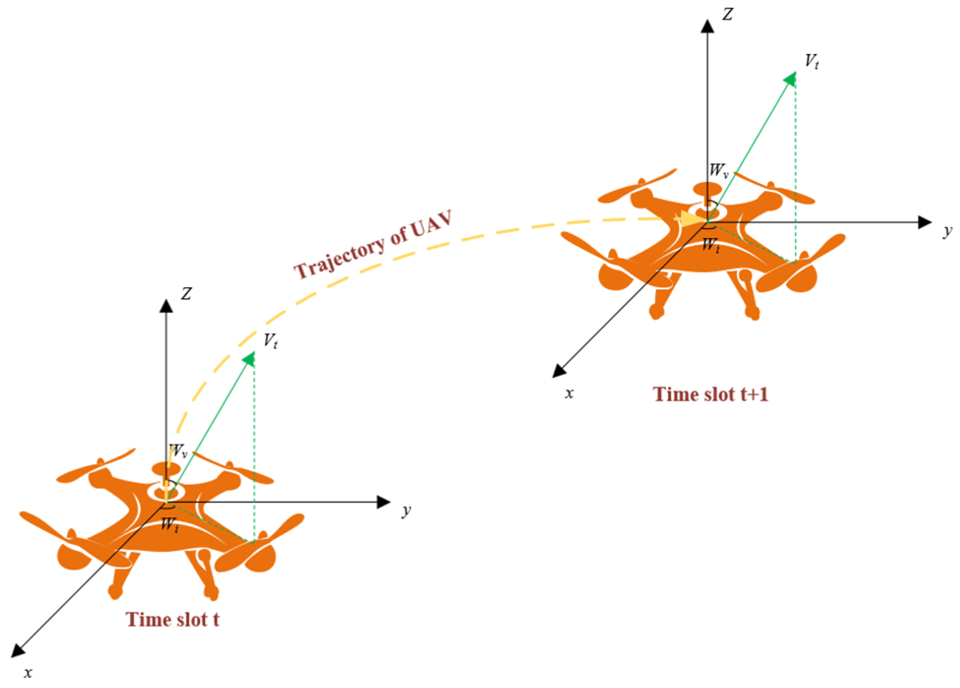
2.2. GD and UAV Mobile Model

At the beginning of the time slot t , each GD generates a computationally intensive task. Regarding the real-time mobile end-user movement, this paper adopts the Gauss–Markov movement model, i.e., the movement of each GD at the current moment is related to its own previous moment’s movement speed and movement angle to be more in line with the objective reality of the GD movement [24]. Therefore, the k th GD’s moving speed v k T U t and moving angle ω k T U t at the current moment are
v k T U ( t ) = γ v k T U ( t 1 ) + ( 1 γ ) v ¯ k + 1 γ 2 φ k
ω k T U ( t ) = γ 1 ω k T U ( t 1 ) + ( 1 γ 1 ) ω ¯ k + 1 γ 1 2 ψ k
where 0 γ 1,0 γ 1 1 refers to the memory level, which indicates the degree of influence of the moving speed and moving angle of the previous time slot on the current time slot state, and v ¯ k and ω ¯ k denote the average moving speed and angle of the k th GD, respectively. φ k and ψ k denote the randomness of the moving speed and the randomness of the moving angle of the k th GD, respectively, and both of them obey Gaussian distribution.
Therefore, the position coordinates of the k th GD at time slot t are
x k T U ( t ) = x k T U ( t 1 ) + v k T U ( t 1 ) cos ( ω k T U ( t 1 ) ) Δ t
y k T U ( t ) = y k T U ( t 1 ) + v k T U ( t 1 ) sin ( ω k T U ( t 1 ) ) Δ t
where t denotes the movement time of the k th GD in two time slot intervals.
In this paper, a 3D dynamics model is used to model the UAV. The position of the UAV is determined by the flight speed, angle, and delay, the angle includes the angle with the XOY plane and the angle with the Z-axis, and the delay includes the flight delay of the UAV and the delay of processing the upload task. Therefore, the position coordinates of the n th UAV at time slot t are
x n U A V ( t ) = x n U A V ( t 1 ) + d i s f l y × cos w i × sin w v
y n U A V ( t ) = y n U A V ( t 1 ) + d i s f l y × sin w i × sin w v
z n U A V ( t ) = z n U A V ( t 1 ) + d i s f l y × cos w v
where ω i is the angle to the XOY plane when the n th UAV is flying, ω v is the angle to the Z-axis when the n th UAV is flying, d i s f l y = v max × ( T n f l y ( t ) + T n , k T r ( t ) ) × v weight , v max denotes the maximum flight speed of the UAV, v weight denotes the velocity component of the UAV, T n f l y ( t ) denotes the flight delay of the UAV, and T n , k T r ( t ) denotes the transmission delay of the UAV unloading task.

2.3. Communication Models

Most existing work uses simplified LoS channels or statistical channel models (i.e., probabilistic LoS channels) to model A2G links. However, traditional probabilistic LoS channel models are often not adapted to complex environments such as rural, urban, and forest environments, and UAVs need to change altitude for better communication. In contrast, we examine more realistic A2G channel models characterized by the consideration of both large-scale fading and small-scale fading, which are computed based on simulating 3D maps and considering the presence of buildings as propagation scatterers [25].
During communication, we determine whether the communication link between the nth UAV and the kth GD is a LoS link by checking whether it is obscured by a building. Therefore, the channel massive fading associated with the kth GD can be expressed as [26]
P L n , k ( t ) = L n , k F S ( t ) + η L o s L n , k F S ( t ) + η N L o s
where L n , k F S ( t ) = 20 log 10 d n , k ( t ) + 20 log 10 f c + 20 log 10 ( 4 π / c ) denotes the free space path loss between the nth UAV and the kth GD, d n , k ( t ) = u n U A V ( t ) u k T U ( t ) denotes the distance from the nth UAV to the kth GD, f c denotes the carrier frequency, and c denotes the speed of light. In addition, η L os and η N L os denote the propagation loss of LoS and NLoS links, respectively.
The small-scale fading coefficients are assumed to be Rayleigh fading in the NLoS case and Rice fading with a 15 dB Rice factor in the LoS case, respectively. Furthermore, it is assumed that the Doppler effect due to UAV mobility can be well estimated and then compensated for at the receiver by using the available state-of-the-art compensation algorithms [27]. Thus, the channel gain from the nth UAV to the kth GD can be expressed as
h n , k ( t ) = 10 P L n , k ( t ) / 20 h ˜ n , k ( t ) .
It is assumed that GDs upload data at a constant transmit power P k to compute a computational task only when they generated that task. The equivalent uplink signal-to-noise ratio (SNR) between the kth GD and the nth UAV at the start of time slot t is as follows:
ρ n , k ( t ) = P k h n , k ( t ) 2 P n
where h n , k ( t ) 2 is the channel power gain between the kth GD of the time slot t and the nth UAV, and P n denotes the power of additive Gaussian white noise (AWGN) at the nth UAV receiver.
Further, the transmission rate between the kth GD and the nth UAV may be expressed as
r n , k ( t ) = Π n , k ( t ) W log 2 ( 1 + ρ n , k )
where Π n , k ( t ) denotes the binary indicator function between the kth GD and the nth UAV, and its value is 1 if the GD offloaded the task to the nth UAV; otherwise, it is 0.
Similarly, the transmission rate between GBS and the kth GD can be expressed as
r m , k ( t ) = Π m , k ( t ) W log 2 ( 1 + ρ m , k )
where Π m , k ( t ) denotes the binary indicator function between the kth GD and the GBS, and its value is 1 if that GD offloaded the task to the GBS; otherwise, it is 0.
The channel model in this paper is able to better describe the communication between UAVs and ground users and is effective when the communication environment is relatively stable in most disaster scenarios [25,26,27].

2.4. Computational Model

In this paper, we adopt a partial offloading strategy; specifically, in time slot t, let the partial offloading variables α m , k t 0,1 ,   α n , k t 0,1 ,   a n d   α l o c a l , k t 0,1 denote the proportions of tasks that are offloaded by the kth GD to the GBS, the nth UAV, and the local computation, respectively. For the kth GD, the offloading strategy needs to be satisfied α l o c a l , k t + α n , k t + α m , k t = 1 .

2.4.1. Local Computation Model

In time slot t, the kth GD chooses to compute part of the task α l o c a l , k t D k t locally, therefore, the kth GD computes locally with a delay of
T k l o c a l ( t ) = α l o c a l , k ( t ) F k ( t ) f k c ( t )
where f k c ( t ) denotes the computational power of the kth GD.
The kth GD calculates the energy consumption locally as
E k l o c a l ( t ) = η 1 f k c ( t ) ϑ 1 F k ( t ) α l o c a l , k ( t )
where η 1 is the effective capacitance switch and ϑ is the normal number, usually taken as 3.

2.4.2. Offloading to GBS Computation Model

In time slot t, the kth GD offloads a part of the task α m , k ( t ) D k ( t ) to the GBS for computation according to the partial offloading strategy, so the total delay for the kth GD to offload a part of the task to the GBS is as follows:
T m , k G B S = T m , k T r ( t ) + T m , k c ( t ) = α m , k ( t ) D k ( t ) r m , k ( t ) + α m , k ( t ) F k ( t ) f m , k c ( t )
where T m , k T r ( t ) and T m , k c ( t ) denote the transmission delay and computation delay of the task offloading to the GBS, respectively, where f m , k c ( t ) is the computation capacity allocated by the GBS to the kth GD. Notably, since the amount of resultant data of the computation task is usually small and the downlink usually has a high transmission rate, the backhaul delay of the computation result can be ignored.
The total energy consumption of the kth GD offloading some tasks to the GBS is
E m , k G B S ( t ) = E m , k T r ( t ) + E m , k c o m ( t ) = P k T m , k T r ( t ) + η 1 f m , k c ( t ) ϑ 1 F k ( t ) α m , k ( t )
where E m , k T r and E m , k c o m denote the transmission energy and computation energy for offloading to GBS, respectively, and P k denotes the transmission power.

2.4.3. Offloading to UAV Computational Model

In time slot t, the kth GD offloads part of the task α n , k ( t ) D k ( t ) to the UAV for computation, so the total delay for the kth GD to offload part of the task to the nth UAV is
T n , k U A V = T n , k T r ( t ) + T n , k c ( t ) = α n , k ( t ) D k ( t ) r n , k ( t ) + α n , k ( t ) F k ( t ) f n , k c ( t )
where T n , k T r ( t ) and T n , k c ( t ) denote the transmission delay and computation delay of task offloading to the nth UAV, respectively, where f n , k c ( t ) is the computational capacity of the nth UAV allocated to the kth GD. As with the offloading to GBS computation, the return delay of the computation results is ignored.
The total energy consumption of the kth GD to offload part of the task to the nth UAV is
E n , k U A V ( t ) = E n , k T r ( t ) + E n , k c o m ( t ) = P k T n , k T r ( t ) + η 1 f n , k c ( t ) ϑ 1 F k ( t ) α n , k ( t )
where E n , k T r ( t ) and E n , k c o m ( t ) denote the transmission energy and computation energy for offloading to the nth UAV, respectively.
In summary, the total time cost of the kth GD computation task D k ( t ) in time slot t can be expressed as
T k ( t ) = max T k l o c a l ( t ) , T m , k G B S ( t ) , T n , k U A V ( t )
where the first part denotes the delay of the local computation part of the task, the second part denotes the delay of the part of the task that is offloaded to the GBS, and the last part denotes the delay of the portion of the task that is offloaded to the nth UAV.

2.5. Flight Model

In this paper, we use a quad-rotor UAV carrying a small MEC server, and we consider the flight vector v , acceleration vector a , vertical deflection angle w v , and horizontal deflection angle w i of each UAV, and the flight trajectory of the UAV is shown in Figure 2.
The nth UAV’s single rotor’s thrust equals [28]
F n ( v n , a n ) = 1 m M 0 a n + 1 2 ρ v n 2 S n v n M 0 g n
where m is the number of rotors of the nth UAV, M 0 is the weight of the nth UAV, ρ is the air density, v n = v n denotes the scalar magnitude of the velocity, S n is the equivalent plane area of the UAV fuselage, and g n is the gravitational acceleration vector.
Based on the individual rotor thrust of the UAV, we can obtain the propulsion power of the nth UAV as follows [28]
P n f l y ( v n , F n ) = m c r 8 F n c t ρ A r + 3 v n 2 F n s r 2 ρ A r c t + 1 + c f F n F n 2 4 ρ 2 A r 2 + v n 2 4 v n 2 2 0.5        + m 0.5 d r v n 3 s r ρ A r + M 0 g n v n m sin π 2 ω v
where c r denotes the local blade section drag coefficient, c t is the thrust coefficient based on the disc area, s r is the rotor solidity, A r is the rotor disc area, and c f and d r are the induced power incremental correction factor and fuselage drag ratio.
Therefore, the flight energy loss of the nth UAV is
E n f l y ( t ) = P n f l y ( t ) T n F l y ( t )
T n F l y ( t ) = max T n , k T r ( t )   k + k = 1 K T n , k c o m ( t )
where denotes the set of the number of GDs that the nth UAV performs the task, we take the maximum delay of the transmission task plus the time taken by the nth UAV to compute the tasks of all the connected GDs K as the flight duration of the nth UAV, denoted by T n F l y ( t ) .

2.6. Problem Construction

In this paper, we address the problem of optimizing the energy consumption of a MEC network for multi-UAV-assisted air–ground collaboration by jointly optimizing the 3D trajectories of the UAVs, the offloading decisions of the GDs, and the allocation of computational resources between the UAVs and the GBS, in an effort to reduce the system’s overall energy consumption.
Firstly, the total energy consumption of UAVs, GBSs, and GDs in time slot t is
E ( t ) = n = 1 N k = 1 K E k l o c a l ( t ) + E n , k U A V ( t ) + + E m , k G B S ( t ) + n = 1 N ξ E n F l y ( t )    n N , k K , t T
where ξ denotes the flight energy consumption weight.
Then, we construct the cooperative resource optimization problem as follows:
CRO :   min Ψ , Θ , f c t = 1 T E ( t )
s . t . C 1 :   0 α m , k ( t ) 1 , 0 α n , k ( t ) 1 , 0 α l o c a l , k ( t ) 1   n N , k K , t T
C 2 :   k = 1 K f n , k c ( t ) f U A V max , k = 1 K f m , k c ( t ) f G B S max   t T
C 3 :   u k T U , u n U A V X s i z e , Y s i z e , H   n N , k K
C 4 :   u n 1 U A V ( t ) u n 2 U A V ( t ) 2 ( d min ) 2   n 1 , n 2 N , t T
C 5 :   v min v n ( t ) v max n N , t T
C 6 :   max T k ( t ) T max ( t )   k K , t T
where Ψ = α m , k ( t ) , α n , k ( t ) , α l o c a l , k ( t )   n N , k K , t T , Θ = v ( t ) , ω v ( t ) , ω i ( t )   t T , and f c = f n , k c ( t ) , f m , k c ( t )   n N , k K , t T . Constraint C1 denotes the offloading decision constraints of UAVs; C2 denotes the limited resources that offloading GDs can be allocated from edge servers; C3 denotes the location constraints of UAVs and GDs; C4 denotes the minimum safe distance between UAVs; C5 denotes the speed constraints of UAVs; and C6 denotes the offloading total delay constraints.

3. Problem Solution

In the process of optimizing UAV trajectories and GD offloading decisions, multiple variables and constraints need to be considered simultaneously, including kinematic constraints of UAVs, positions of GDs, and mission requirements, while computational resource allocation is optimized for the amount of tasks offloaded to UAVs or GDs. Thus, the UAV trajectory and GD offloading decisions are uncertain, while the computational resource allocation decisions are relatively more deterministic. Further, the CRO problem is split into task offloading, flight trajectory (Q1) sub-problems, and computational resource allocation (Q2) sub-problems, and such sub-problem splitting helps to improve the optimization efficiency and performance of the overall system.
The mission offloading and flight trajectory (Q1) sub-problem is a complex decision-making problem involving strategy optimization in dynamic and uncertain environments. There are dynamic changes and interactions between the various agents (UAVs and GDs). To solve this sub-problem, the MATD3 algorithm is used. The MATD3 algorithm is suitable for dynamic and uncertain environments where the agents are able to optimize the overall system performance by learning their respective strategies. In contrast, for the computational resource allocation (Q2) sub-problem, a convex optimization approach is used to determine the optimal resource allocation for tasks offloaded to UAVs or GBS. These two algorithms are alternately updated in interaction and can effectively solve the joint optimization problem of UAV trajectory optimization, GD offloading decision, and resource allocation.
As shown in Figure 3, we designed the splitting of the optimization problem and the solving process of the sub-problems. During the optimization process, the two algorithms are alternately updated to solve the joint optimization problem of UAV trajectory optimization, GD offloading decision, and resource allocation. The specific process is as follows: firstly, the task offloading decision and flight trajectory are determined based on the input local observation data of the MATD3 algorithm, and then the computational resource allocation is obtained through the optimal solution based on the task volume of the task offloading decision. Subsequently, in the edge computing environment, using the joint decision of task offloading, flight trajectory, and computational resource allocation, the corresponding reward is calculated by designing the reward function, and the procedure will continue to train until the training is completed and converged.
In this regard, we aim to provide a fundamental technological solution for disaster relief by enhancing the efficient use of task offloading and computational resources. In the implementation of the proposed algorithm, each GD is regarded as an independent agent, which is able to dynamically adjust the task offloading ratio according to their respective task characteristics, and at the same time, by optimizing the UAV and GBS task scheduling and computational offloading in order to obtain the optimal performance, the offloading efficiency can be indirectly improved, which can further provide technological guarantee for the rescue operation. Meanwhile, the optimization algorithm based on the combination of DRL and convex optimization is of great significance in solving optimization problems. This combination can make full use of the adaptive learning ability of DRL and the mathematical guarantee of convex optimization to cope with complex and dynamic environments. It not only improves the decision-making ability and computational efficiency of the system, but also achieves comprehensive optimization and improves the overall performance and stability of the system.

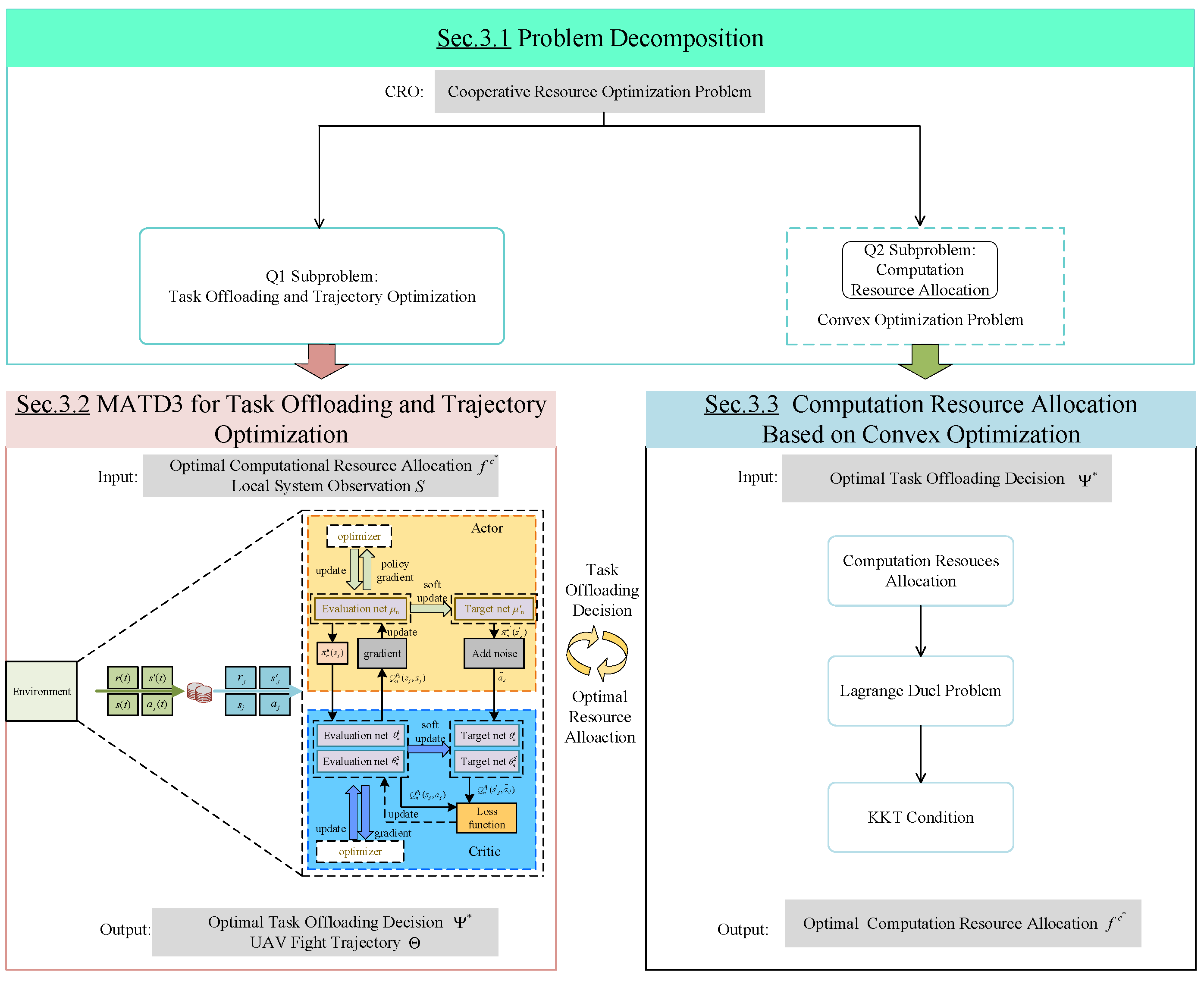
3.1. Problem Decomposition

In this section, we first break down the CRO into multiple problems for each time slot. Since the variables Ψ , Θ , and f c are independent of each other in time slot t, the constraints can be separated since there is no overlap between the variables, and the main optimization problem can be divided into two sub-problems, formulated as follows.

3.1.1. Sub-Problem Q1: Task Offloading and Trajectory Optimization

Q 1 :   min Ψ , Θ E ( t )
s . t . C 7 :   0 α m , k ( t ) 1 , 0 α n , k ( t ) 1 , 0 α l o c a l , k ( t ) 1   n N , k K , t T
C 8 :   u k T U , u n U A V X s i z e , Y s i z e , H   n N , k K
C 9 :   u n 1 U A V ( t ) u n 2 U A V ( t ) 2 ( d min ) 2   n 1 , n 2 N , t T
C 10 :   v min v n ( t ) v max   n N , t T
C 11 :   max T k ( t ) T max ( t )   k K , t T .

3.1.2. Sub-Problem Q2: Computational Resource Allocation

Sub-problem Q2 focuses on the computational resource allocation f c , the edge end. After sub-problem Q1 makes the optimal offloading decision Ψ * through the MATD3 algorithm, Q2 can be formulated as
min f c E ( t )
s . t . C 12 :   k = 1 K f n , k c ( t ) f U A V max , k = 1 K f m , k c ( t ) f G B S max ,   t T .
Since we are investigating the use of computational resource allocation only when GDs choose to offload some of their tasks to the edge end, the only energy consumption involved in the optimization variable f c is the computational energy consumption of offloading to the GBSs and the UAVs, and thus, from (17) and (19), the problem Q2 can be reduced to
min f c k = 1 K E n , k c o m ( t ) + E m , k c o m ( t )
s . t . C 13 :   k = 1 K f n , k c ( t ) f U A V max , k = 1 K f m , k c ( t ) f G B S max ,   t T .

3.2. MATD3 Algorithm for Task Offloading and Trajectory Optimization

In the disaster scenario, we interact the GD and UAV as two separate classes of agents. The goal of the GD agent is to optimize task processing, which requires a decision on the proportion of offloading to the edge, while the goal of the UAV agent is to optimize the flight trajectory, to adjust the flight path to compute the task, and improve efficiency. Through DRL, these two agents can continuously improve their strategies through dynamic interaction and feedback to achieve more efficient task processing and resource usage.
In the problem optimization process, UAVs need to determine the location of the next moment of flight to minimize energy consumption, and GDs need to determine the target node for task offloading so as to reduce the task transmission and processing energy consumption. Considering that the actions of UAVs and GDs at this moment may affect the state of the environment, and that the total energy consumption is jointly determined by the behaviors of GDs and UAVs in the current state, i.e., the current state of the environment, and the actions of the agents work together to bring the environment into the next random state. Therefore, the optimization problem of UAV trajectory optimization and GD task offloading can be represented as a multi-agent Markov decision process N , S , A , P , R , where N , represents the collection of all agents, S is the collection of states of all agents in the environment, A is the collection of actions of all agents, P is the state transfer probability, and R is the reward function of the agents.
  • States S .
The location and computational power where GD, UAV, and GBS are located are the key factors affecting the unloading of GD, so the state space of GD is
s x , k , s y , k , s z , k , s c , k , s x , n , s y , n , s z , n , s c , n , s x , m , s y , m , s z , m , s c , m   k K , n N
where s x , k , s y , k , s z , k , and s c , k are the location and computational power state of the kth GD, s x , n , s y , n , s z , n , and s c , n are the location and computational power state of the nth UAV, and s x , m , s y , m , s z , m , and s c , m are the location and computational power state of the GBS, respectively.
The state space of the UAV is the state of all GDs, the UAV position, the processing capacity, and the energy consumption, so the state space of the UAV is
s x , k , s y , k , s z , k , s c , k , s x , n , s y , n , s z , n , s c , n , s com c o m , n , s t r a n , n , s f l y , n   k K , n N
where s c o m , n , s t r a n , n , and s f l y , n are the computational energy, task transfer energy, and flight energy states of the UAV, respectively.
  • Actions A .
Since this paper uses a partial offloading mechanism, the action of each GD is the proportion of tasks that are offloaded to each node, so the action of the GD agent output is defined as
a t k = α l o c a l , k ( t ) , α n , k ( t ) , α m , k ( t )   k K , n N , t T
where α l o c a l , k ( t ) represents the proportion of tasks that the kth GD offloaded to itself, α n , k ( t ) represents the proportion of tasks that the kth GD offloaded to the nth UAV, and α m , k ( t ) represents the proportion of tasks that the kth GD offloaded to the GBS.
The actions optimized for each UAV trajectory are the velocity, horizontal deflection angle, and vertical deflection angle of the UAV in the 3D scene; therefore, the actions output by each UAV agent are defined as
a t n = v n ( t ) , ω i ( t ) , ω v ( t )   n N , t T
where v n ( t ) represents the flight speed of the nth UAV, ω i ( t ) represents the horizontal deflection angle of the nth UAV, and ω v ( t ) represents the vertical deflection angle of the nth UAV.
  • Reward R .
Since the GD determines the offloading decision of the task when acting as an agent, the reward function associated with the GD is
r t k = E k l o c a l ( t ) + E n , k U A V ( t ) + E m , k G B S ( t ) + T k ( t )   k K , n N , t T .
Since the computational energy consumption and flight energy consumption are the key energy consumption in this paper, and the computational delay is the key index, and the UAV moving range must not exceed the environment boundary and collision; therefore, the reward function of the UAV is designed as the negative of the weighted sum of the task computational delay, the computational energy consumption, the flight energy consumption, and the penalty for the collision of the UAV overstepping the boundaries, i.e.,
r t n = k = 1 K E n , k U A V ( t ) + ξ E n F l y ( t ) + T n , k U A V ( t ) + P e n   k K , n N , t T
where K denotes the number of GDs chosen to be offloaded to the nth UAV, and P e n is the collision and crossing penalty for the nth UAV.
In order to solve the above multi-intelligent body Markov decision-making process, this paper proposes a MATD3-based trajectory optimization and task offloading algorithm for UAVs. Each GD and UAV as an agent is optimized for its respective task using the TD3 algorithm, which is an online heterogeneous deep reinforcement learning algorithm for continuous control problems obtained by improving on the DDPG algorithm. Essentially, the TD3 algorithm incorporates the idea of the double Q learning algorithm into the DDPG, which consists of six networks, namely actor network π ( | θ π ) , target actor network π ( | θ π ) , critic networks μ 1 ( | θ μ 1 ) and μ 2 ( | θ μ 2 ) , and target critic networks μ 1 ( | θ μ 1 ) and μ 2 ( | θ μ 2 ) , where θ is the parameter of each network. The algorithm uses two critic networks in order to take the smaller of the two when calculating the target value, thus suppressing the network overestimation problem.
The MATD3 algorithm uses an optimal optimization process with centralized training and decentralized execution, so that during the iteration process, each UAV and GD as an agent performs actions in a distributed manner through observations, and the performed actions are mapped to the environment translated into the position of the UAV and the nodes and proportions of the GD task offloading. By interacting with the environment, the agents store the collected experience into an experience pool for centralized training. In the centralized training phase, the UAV and the GD share their state information, and then each agent uses the state S t as well as A t = a t 1 , a t 2 , , a t k , , a t n to estimate the strategies of the other agents and obtains the Q-function Q k μ ( s t , a t ) for all the agents. Then, each agent adjusts the local actor network strategy v k π = π ( s t | θ μ ) to maximize its own utility. In the distributed action session, the critic network of each agent is no longer used and the weight parameter of the actor network remains unchanged. This decentralized execution can greatly improve the flexibility of the decision making of the agents.
In the MATD3-based UAV trajectory optimization as well as task offloading algorithm, the environment parameters, as well as the network parameters, are first initialized. At each iteration, all the agents select actions using the evaluation actor network π ( s k , t | θ π ) , and to increase the exploration rate, random noise ε is added after each action and cropped according to its action threshold. The agent maps the selected action to the environment, and based on this action, the GD offloads proportionally to the task and the UAV changes its position, thus completing the trajectory optimization and calculates the task transmission and processing delay, as well as task transmission processing energy consumption and UAV flight energy consumption through the obtained performance indicators, each agent according to the reward function to calculate the reward value. At this time, all agents will obtain a set of experience a t , s t , s t , r t and store this into the playback experience pool with capacity M to improve the sample efficiency. Then, experience a j , s j , s j , r j of size batch size is randomly selected from the experience pool for training. Each agent will use the policy gradient to update the target actor network weights, i.e.,
θ π J ( θ π ) = 1 M b a t c h j = 1 M b a t c h θ μ μ ( s j | θ π ) a k a n Q θ 1 ( s j , a 1 j , a n j , , a N j ) | a = π ( s k j | θ π ) ,
agent input s j into the target actor network π ( | θ π ) to generate strategies
a = π ( s j | θ π ) .
Deterministic strategies can over-fit to reduce the value estimates’ peaks. When the critic network is updated, the learning objective using the deterministic strategy is highly susceptible to function approximation errors, which leads to large variance in the objective estimate and inaccurate estimates. Therefore, when calculating the target value, TD3 adds a perturbation to the action in the next state using the objective strategy smooth regularization, which prevents over-fitting of the Q-value and makes the value estimation more accurate. The modified action is defined as
a = a + ε
ε ~ c l i p ( N ( 0 , ζ ) , 1 , 1 ) .
Then we use the idea of dual networks to calculate the target value
y j = r j + γ min i = 1 , 2 μ i ( s j , a j | θ μ i ) .
Finally, the gradient descent method is used to minimize the error between the assessed and target values
L ( θ n , k i ) = 1 M b a t c h j = 1 M b a t c h y j ψ i ( s , a | θ μ i ) 2 ,   i = 1 , 2 .
According to the above equation, the weights of the three networks of each agent will be updated by
θ n , k π θ n , k π ω θ n , k π J ( θ n , k π ) , θ n , k μ i θ n , k μ i ω θ n , k μ i L ( θ n , k μ i ) ,   i = 1 , 2
where ω is the learning rate. In order to reduce the error between the evaluated value and the target value, the agent updates the evaluation actor network at a fixed frequency. Finally, the weights of the target network are softly updated with the update rate τ according to the following equation:
θ n , k π = τ θ n , k π + ( 1 τ ) θ n , k π , θ n , k μ i θ n , k μ i + ( 1 τ ) θ n , k μ i ,   i = 1 , 2
The total pseudo code of the MATD3-Based GD Task Offloading and UAV Trajectory Optimization algorithm is shown in Algorithm 1:
Algorithm 1: MATD3-Based GD Task Offloading and UAV Trajectory Optimization
1.
   Initialize actor and critic networks for each agent, playback experience pools D ;
2.
   for each episode do
3.
    Initialize the state s ( t ) and t = 0 ;
4.
    while t < E P do
5.
     Each UAV and GD select the action;
6.
     All UAVs set the angle and speed of their movement according to the joint action a ( t ) , and each GD selects the offloading decision;
     The optimal computational resource allocation decision is computed by (47) and (48) based on the amount of tasks offloaded by each UAV and GBS;
7.
     All UAVs and GDs communicate to obtain the reward r ( t ) , the next state s ( t + 1 ) and the joint action a ( t ) ;
8.
     for all agents, store s ( t ) , s ( t ) , a ( t ) , r ( t ) in D ;
9.
      s ( t ) s ( t + 1 ) ;
10.
  for agent
11.
    A small batch ( s j , s j , a j , r j ) is randomly sampled from the in which the intelligence is located;
    Update the weights for evaluating the critic network by minimizing the loss function L ( θ k , n i ) in (41) θ k , n i , i = 1 , 2 ;
    Update the weights of the evaluated actor network via (42);
    By updating the weights of the three target networks in (43);
12.
  End for
13.
End for
14.
End for
The flow of the proposed algorithm can be described as follows:
Firstly, the weights of the actor and critic networks and the pool of playback experience used for the actor and critic networks are initialized, (line 1). The second part (lines 3–9) is the process of exploration. At the beginning of each round, the algorithm initializes the environment and receives the initial state, the time slot set to 0, and the termination state. Then, during the exploration process, an action is deduced from the current actor network, which subsequently interacts with the environment and is updated accordingly with the corresponding reward and next state. The third part is how to update the neural network (line 11). Specifically, we first sample a small batch of samples stored into the pool of playback experience (line 14) to update the actor and critic networks. The critic network is updated by minimizing the loss function; the actor network is updated by computing the gradient.

3.3. Computational Resource Allocation Based on Convex Optimization

The computational resource allocation optimization problem associated with the UAV can be formulated as Q3 for GD offloading part of the task to the UAV in time slot t
Q 3 :   min f n , k c z 1 = k = 1 K E n , k c o m ( t )   n N , k K
s . t . C 14 :   k = 1 K f n , k c ( t ) f U A V max , t T .
To solve the convex optimal computational resource allocation problem: by introducing Lagrange multiplier, transforming the resource constraints into additional terms in the optimization problem, and then solving the KKT conditions, the resource allocation strategy that maximizes the benefits of the GD task completion can be found.
We first use the Lagrange duality method to introduce the Lagrange multiplier λ n t to Q3 [29], and then the problem of Q3 can be formulated as
min λ n t , f n , k c ( t ) z 2 = z 1 λ n t ( k = 1 K f n , k c ( t ) f U A V max )
s t C 15 :   λ n t 0 .
Based on the KKT condition [29], we can derive the following equation:
f n , k c ( t ) z 1 + λ n t f n , k c ( t ) ( k = 1 K f n , k c ( t ) f U A V max ) = 0 λ n t ( k = 1 K f n , k c ( t ) f U A V max ) = 0 . λ n t 0
By solving the above system of equations, the optimal solution for the computational resource allocation obtained when the kth GD offloads part of the task α k , n ( t ) D k ( t ) to the nth UAV in time slot t is obtained as follows:
f n , k c * ( t ) = 1 / f U A V max α k , n D k ( t ) F k ( t ) k = 1 K 1 / f U A V max α k , n D k ( t ) F k ( t ) .
Similarly, the optimal solution for computational resource allocation obtained when the kth GD offloads part of the task α k , m ( t ) D k ( t ) to the GBS in time slot t is obtained as follows:
f m , k c * ( t ) = 1 / f G B S max α k , m D k ( t ) F k ( t ) k = 1 K 1 / f G B S max α k , m D k ( t ) F k ( t ) .

4. Simulation Parameter Design and Simulation Result Analysis

In this section, we first set the simulation parameters, including environment parameters and algorithm hyper-parameters, and then analyze the simulation results, including the effects of different offloading methods, different environment parameters, and algorithm hyper-parameters on the system performance indicators.

4.1. Simulation Parameter Design

In this paper, we consider a 3D simulation region of 1000   m × 1000   m × 200   m in which 1 GBS, 2 UAVs, and 10 GDs are considered, each GD is capable of randomly generating tasks of a certain size and selecting the offloading nodes and scaling, and the UAVs are initially hovering at an altitude of 100 m and with the algorithmic iterations can change the altitude to keep flying.
For the simulation environment, we implement a simulation environment build using Python 3.8.0 and Pytorch 2.1.2 to evaluate the performance of the proposed algorithm. The simulation was run using a PC equipped with an AMD Core R7 CPU, 512 GB of RAM, and 16 GB of RAM. The version Numpy utilized in the simulation is 1.22.4. In the initialization phase of the simulation environment, the initial positions of the UAVs and GDs are randomly generated based on the size of the boundary of the simulation environment and the computational tasks are randomly generated for each GD in a set range of task sizes.
The specific simulation parameters are shown in Table 1 and Table 2:

4.2. Analysis of Simulation Results

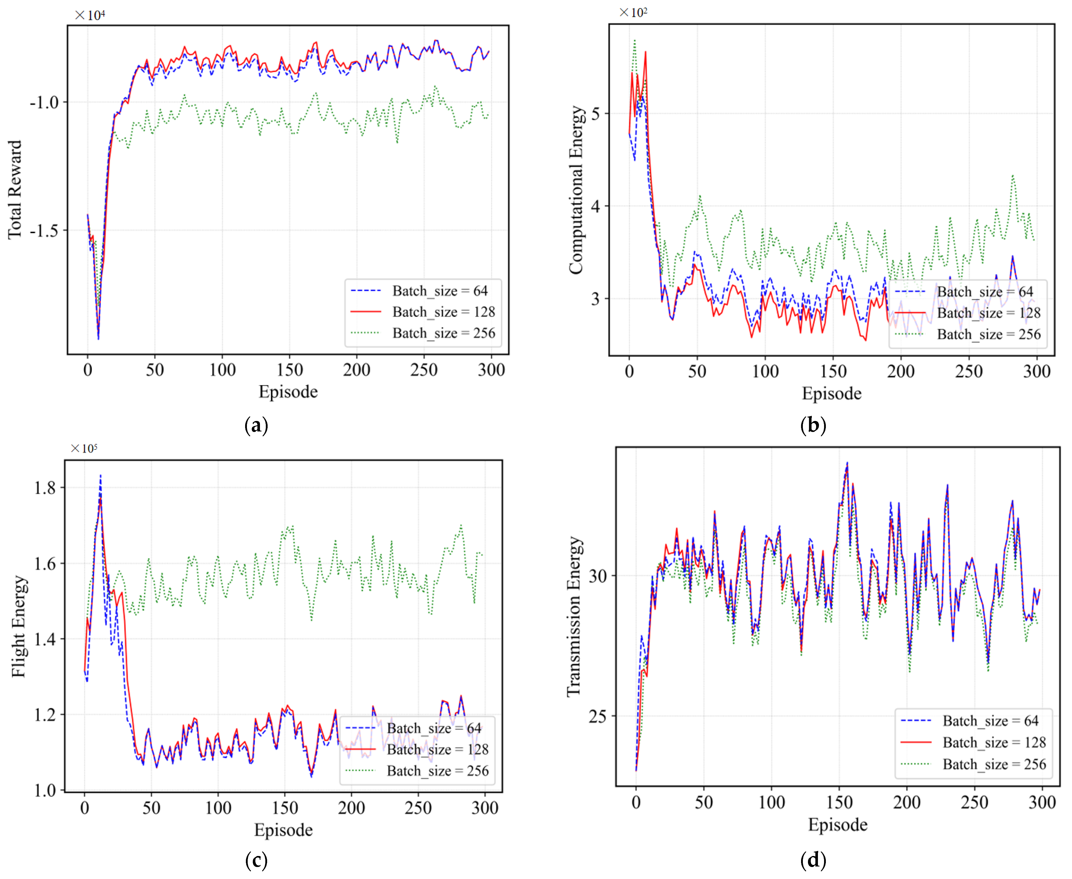
4.2.1. Effect of Different Batch_Sizes

In deep reinforcement learning, the batch_size is the number of samples randomly drawn from the empirical playback buffer for each training. Larger batch_size improves training efficiency, stability, and convergence, but increases the training time and the risk of over-fitting. Smaller batch_size leads to instability in gradient estimation, high variance in parameter updates, and under-utilization of information, making the training process more difficult, convergence slower, and making it difficult to obtain high-quality policies. From Figure 4a–d, it can be seen that when the batch_size is 128, its total reward, computational energy, flight energy, and transmission energy are all at their lowest values, and thus the batch_size suitable for our proposed environment and algorithms is 128. On the other hand, it can be seen from the figure that the curves obtained when the batch_size is 64 are roughly the same as those obtained when the batch_size is 128; this is because deep reinforcement learning algorithms usually use experience playback buffers to store and reuse past experiences, and even if the batch_size is small, by repeatedly utilizing these experiences for training, the algorithm can obtain sufficient sample diversity and information from the entire data-set. As a result, the algorithm is able to learn similar strategies from the entire data-set, even though the number of samples used in each training step varies.

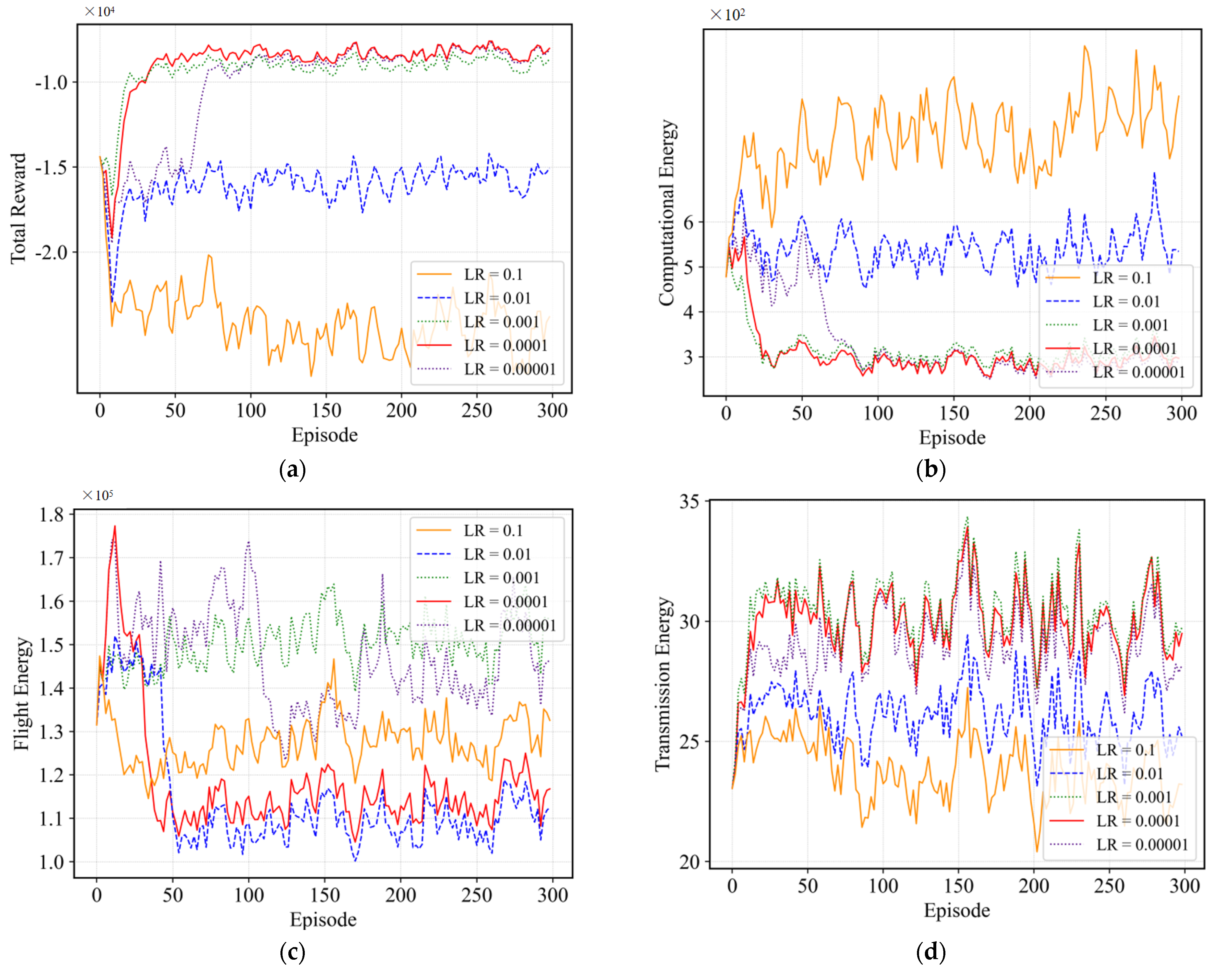
4.2.2. Effect of Different Learning Rates

The learning rate is an important hyper-parameter in deep reinforcement learning, which controls how much the network parameters are tuned at each update. In terms of convergence speed, a larger learning rate allows the parameters to be adjusted to the neighborhood of the optimum faster, speeding up convergence. However, an excessive learning rate could result in the parameters oscillating around the optimal point and not achieving a stable convergence. On the contrary, a smaller learning rate may require more training steps to reach the optimal value, resulting in slower convergence, and too small a learning rate may result in too small a parameter update, which does not make full use of the training data during the training process, causing the algorithm to fall into a local optimum during the optimization process. From Figure 5a–d, it can be seen that when the learning rate is 0.0001, although the flight energy consumption and transmission energy consumption do not reach the minimum, due to its lower computational energy consumption, it makes the total reward value the highest, because our algorithm uses a learning rate of 0.0001.

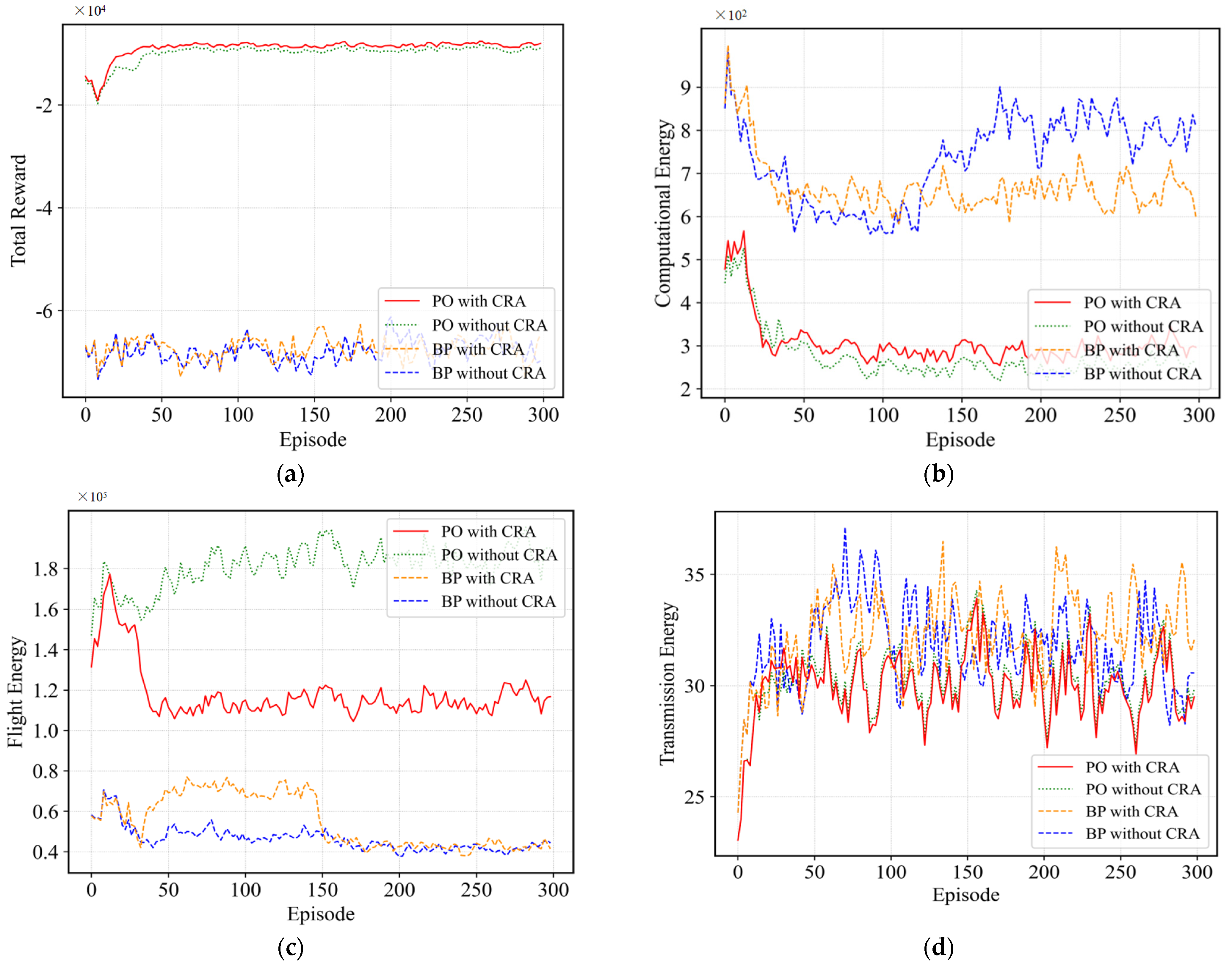
4.2.3. Effect of Computational Resource Allocation and Partial Offloading

In the task offloading environment, the way of computational resource allocation and partial offloading can greatly improve the flexibility of task offloading and processing. Therefore, after determining two important hyper-parameters, namely algorithm learning rate and batch_size, this paper verifies the effects of computational resource allocation and the partial offloading approach on various performance metrics. Where CRA stands for computational resource allocation, PO stands for partial offloading method, and BP stands for binary offloading method. From Figure 6a, it can be seen that with the partial offloading approach in the presence of both partial offloading approaches, the reward obtained with computational resource allocation is higher than that without computational resource allocation, while with the partial offloading approach in the presence of both computational resource allocations, the reward value obtained with the addition of partial offloading approach is much higher than that of the binary offloading approach, which is due to the fact that in the resource-limited environment, all the tasks generated by the GD are offloaded to a single processing node, which tends to cause processing congestion, increase task processing latency and energy consumption, and significantly reduce resource utilization. Therefore, synthesizing Figure 6a–d, it can be seen that in the environment designed in this paper, the computational resource allocation combined with the partial offloading approach can greatly reward the latency and energy consumption, and thus increase the total system reward.

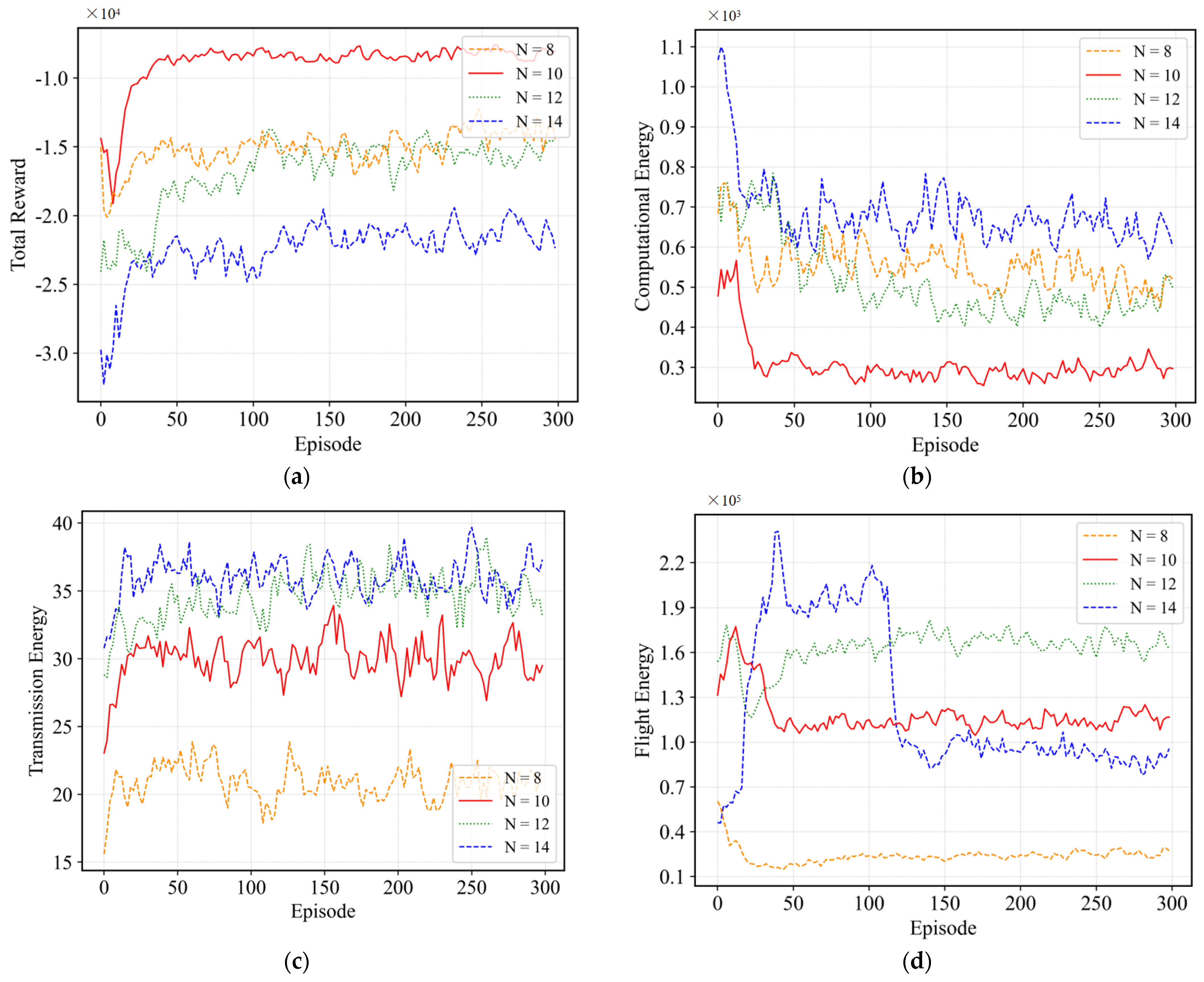
4.2.4. Effect of the Number of GDs

GDs serve as agents constitute the crucial factors influencing the environment, so in this paper, different numbers of GDs are simulated for various performance metrics. From Figure 7a–d, it can be observed that the lower the number of GDs, the lower the task computation energy, flight energy, and transmission energy, which results in a higher total system reward. Consequently, the lower the number of GDs, the fewer tasks are generated, so the lower the transmission energy consumption and flight energy consumption; and when fewer tasks are generated, the more computational resources are allocated to each task, so its computational delay is lower and its computational energy consumption becomes lower accordingly, which validates the reasonableness of the environment design.

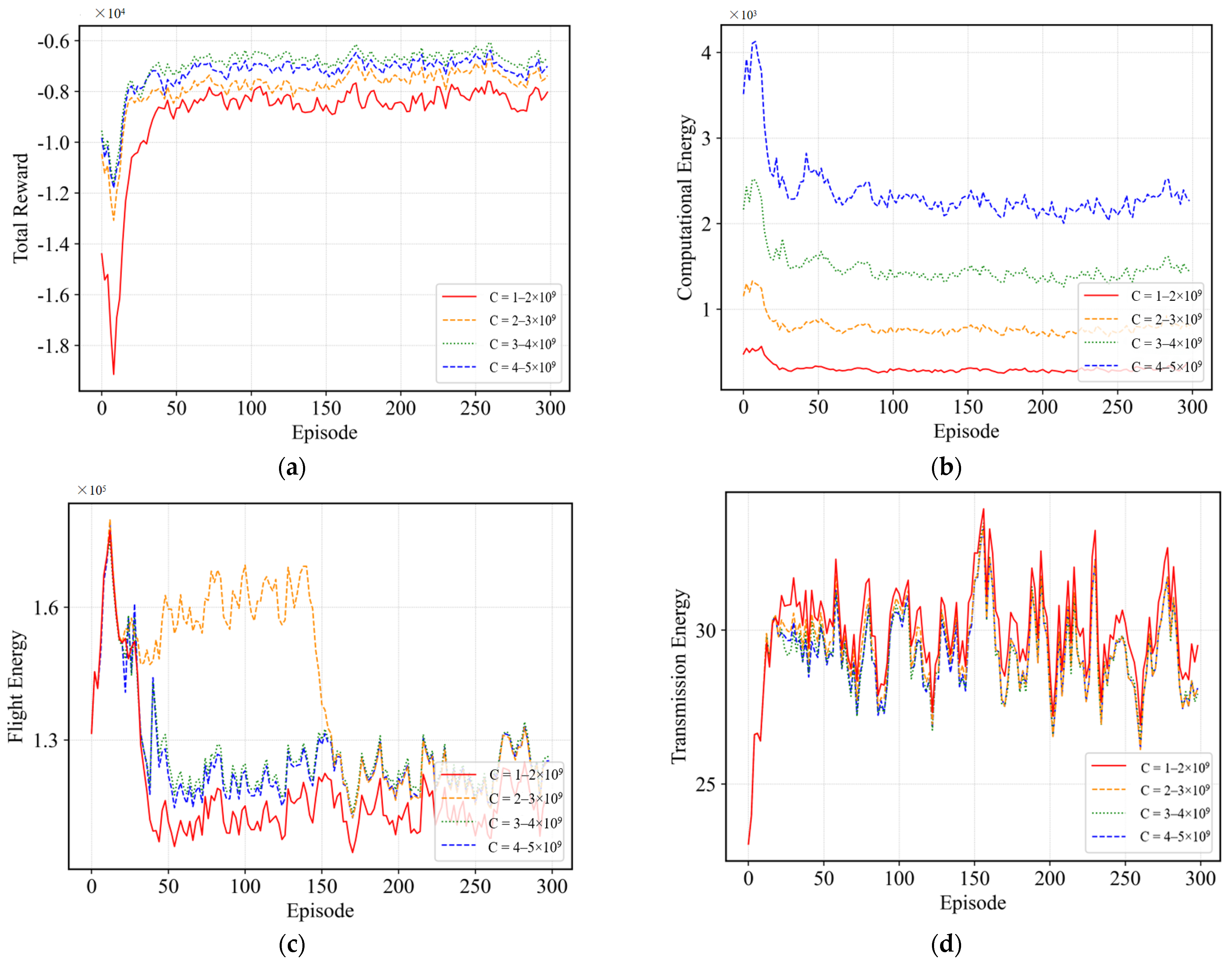
4.2.5. Effect of GDs Computing Power

Secondly, we evaluate the effect of GDs’ computational power on each index by changing the computational power of GDs to verify the performance of the algorithm. From Figure 8a–d, it can be seen that the larger the computational power of the GDs, the smaller the value of its various energy consumption, which is because the larger the computational power of the GDs, then the GDs are more biased to process more tasks by themselves, and thus the transmission of the tasks and the flight of the UAVs consume less energy. Moreover, due to the increase in GD computational power, the total computational resources in the scene increase, and then the computational delay of the tasks decreases, which leads to the decrease in the total computational energy consumption in the system environment, further verifying the reasonableness of the environment proposed in this paper as well as the effectiveness of the proposed algorithms.

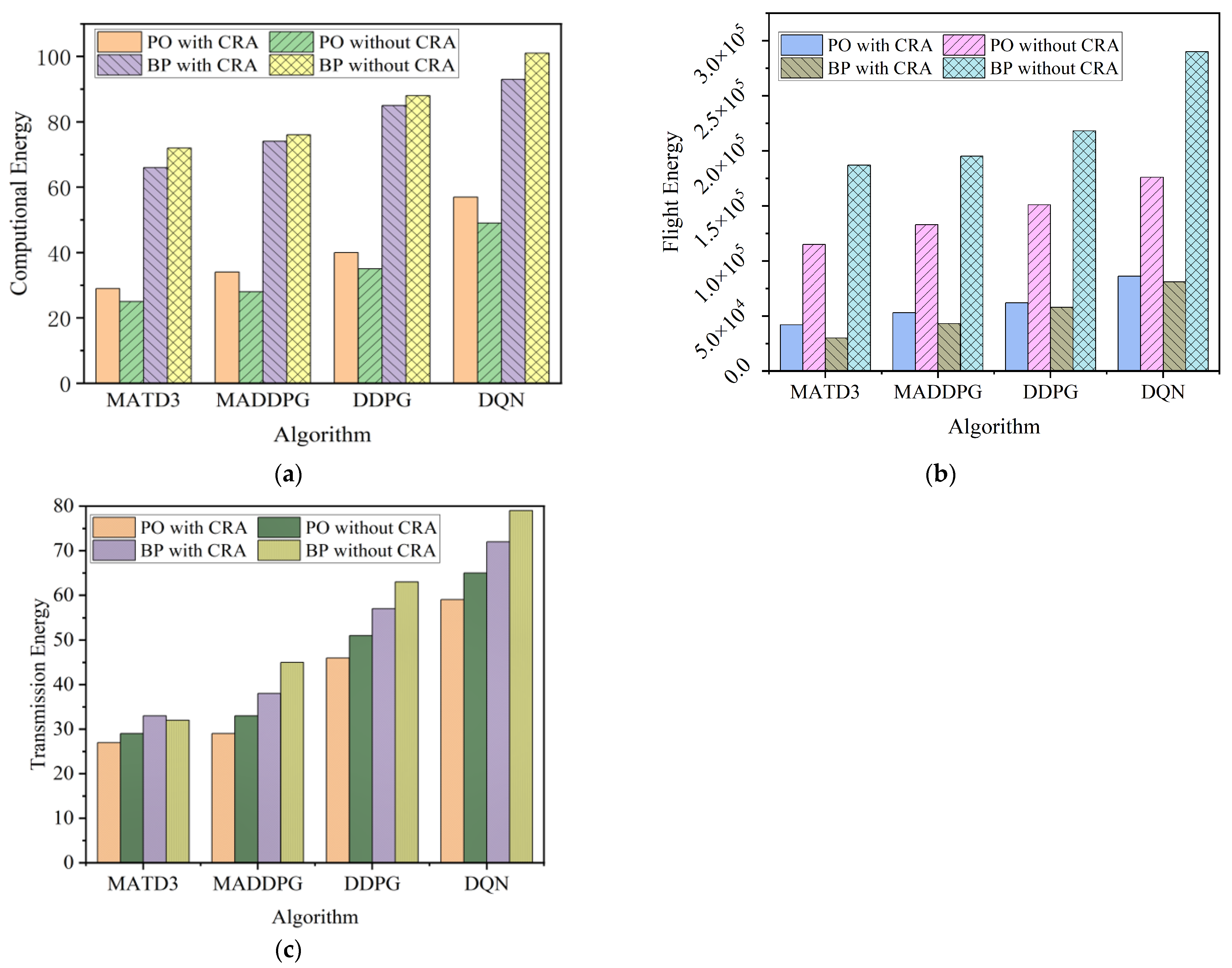
4.2.6. Comparison of This Paper’s Algorithm with the Benchmark Algorithm

For performance comparison, we implemented the following comparison of three benchmark algorithms:
MADDPG [30]: consistent with the proposed algorithm, differing in the DDPG algorithm used by each agent for action optimization.
DDPG [31]: The global state of the system is constructed by splicing the local observations of each agent and feeding them into the DDPG algorithm, which determines the task offloading decision and transmission power allocation uniformly, and subsequently maps its decisions to each agent. The reward function uses the weighted sum of all the agents as the total reward.
DQN [32]: Similar to DDPG, the difference is that in the construction of the construction of the action space, for the unloading decision of the part of the unloading needs to be discretized. We rely on this literature to follow the same discretization.
(1) Comparison of energy consumption between the algorithm in this paper and the benchmark algorithm: Figure 9a–c shows bar charts illustrating the energy consumption of this paper’s algorithm compared to the benchmark algorithm. Where CRA stands for computational resource allocation, PO stands for partial offloading method, and BP stands for binary offloading method. As can be seen from the figure, regardless of whether partial offloading or binary offloading is used, the MATD3 algorithm we use consumes less energy than the other benchmark algorithms, has the lowest cost, and is effective in reducing the resource utilization when combined with computational resource allocation.
(2) Comparison of this paper’s algorithm with the benchmark algorithm for negative total rewards at different task arrival rates: The bar charts in Figure 10 show the performance of this paper’s algorithm and the benchmark algorithm under 10 GD scenarios with different task arrival rates in terms of the reward negative value. The tasks of GD within each time slot are randomly generated based on the task probability model. As can be seen from Figure 10, the reward negative value gradually increases with the increase in task arrival rate, which indirectly reflects the gradual decrease in the reward value. The reason is that a lower task arrival rate implies a smaller number of tasks with a fixed total time slot, which further reduces the energy consumption for transmission and computation. In contrast, the negative reward value of this paper’s algorithm is always higher than that of the benchmark algorithm, which further validates the effectiveness of this paper’s algorithm.
(3) Comparison of this paper’s algorithm with the benchmark algorithm for negative total rewards at different task load range size: The bar chart in Figure 11 demonstrates the effect of this paper’s algorithm and the benchmark algorithm on the negative rewards at different task load ranges, from which it can be seen that the negative rewards usually show an upward trend as the task load range increases. This indicates that as the system burden increases (i.e., the task load range expands), the performance burden of the system increases, which leads to an increase in the negative reward, and the negative reward of this paper’s algorithm is always higher than other benchmark algorithms, which effectively reduces the performance burden of the system.

5. Conclusions

In this paper, a 3D dynamic multi-UAV-assisted air–ground collaborative MEC system model is constructed. Specifically, the task offloading decision of GDs, the UAV flight trajectory, and the computational resource allocation problem of edge-end nodes are, respectively, discussed. Then, to minimize the total energy consumption of the system, the CRO problem is proposed herein. Furthermore, the problem is decoupled into two sub-problems based on the correlation of the tasks. We take advantage of the DRL and adopt the MATD3 algorithm to jointly optimize the task offloading and flight trajectory problems, and subsequently, the optimal solution for the computational resource allocation of the edge nodes is derived based on the KKT condition. The two sub-problems interact until the MATD3 algorithm converges. Finally, the simulation results validate the rationality and effectiveness of our algorithm. In our future work, we gradually carry out tests of realistic scenarios and observe the impact of communication interference, interruption, and channel deterioration on system performance in extreme environments, especially in conjunction with the actual needs of disaster relief, to deploy and validate the algorithms, to collect more real-world data, and to further optimize the algorithm performance.

Author Contributions

Conceptualization, M.W., R.L. and M.G.; methodology, M.W., R.L. and M.G.; software, R.L. and M.G.; validation, R.L. and M.G.; writing—original draft preparation, R.L.; writing—review and editing, M.W., R.L. and M.G.; visualization, M.W., R.L. and M.G.; supervision, M.W., R.L. and M.G.; project administration, M.W., R.L., F.J. and M.G. All authors have read and agreed to the published version of the manuscript.

Funding

Information and Communication Business Cost Project of JSCMC, Grant/Award Number: SXJD-XXTXF-202303; Scientific Research Plan of JSLLKYJH, Grant/Award Number: 23-JSLLKY011.

Institutional Review Board Statement

Not applicable.

Informed Consent Statement

Not applicable.

Data Availability Statement

The raw data supporting the conclusions of this article will be made available by the authors on request.

Conflicts of Interest

The authors declare no conflict of interest.

References

  1. Zheng, Y.J.; Chen, Q.Z.; Ling, H.F.; Xue, J.Y. Rescue Wings: Mobile Computing and Active Services Support for Disaster Rescue. IEEE Trans. Serv. Comput. 2016, 9, 594–607. [Google Scholar] [CrossRef]
  2. Wang, Y.; Su, Z.; Zhang, N.; Fang, D. Disaster Relief Wireless Networks: Challenges and Solutions. IEEE Wirel. Commun. 2021, 28, 148–155. [Google Scholar] [CrossRef]
  3. Zhou, F.; Hu, R.Q.; Li, Z.; Wang, Y. Mobile Edge Computing in Unmanned Aerial Vehicle Networks. IEEE Wirel. Commun. 2020, 27, 140–146. [Google Scholar] [CrossRef]
  4. Dai, Z.; Xu, G.; Liu, Z.; Ge, J.; Wang, W. Energy Saving Strategy of UAV in MEC Based on Deep Reinforcement Learning. Future Int. 2022, 14, 226. [Google Scholar] [CrossRef]
  5. Liu, L.; Wang, A.; Sun, G.; Li, J. Multiobjective Optimization for Improving Throughput and Energy Efficiency in UAV-Enabled IoT. IEEE Internet Things J. 2022, 9, 20763–20777. [Google Scholar] [CrossRef]
  6. Bai, T.; Wang, J.; Ren, Y.; Hanzo, L. Energy-Efficient Computation Offloading for Secure UAV-Edge-Computing Systems. IEEE Trans. Veh. Technol. 2019, 68, 6074–6087. [Google Scholar] [CrossRef]
  7. Alsamhi, S.H.; Shvetsov, A.V.; Kumar, S.; Shvetsova, S.V.; Alhartomi, M.A.; Hawbani, A.; Rajput, N.S.; Srivastava, S.; Saif, A.; Nyangaresi, V.O. UAV Computing-Assisted Search and Rescue Mission Framework for Disaster and Harsh Environment Mitigation. Drones 2022, 6, 154. [Google Scholar] [CrossRef]
  8. Munoz, O.; Pascual-Iserte, A.; Vidal, J. Optimization of Radio and Computational Resources for Energy Efficiency in Latency-Constrained Application Offloading. IEEE Trans. Veh. Technol. 2015, 64, 4738–4755. [Google Scholar] [CrossRef]
  9. Wang, S.; Huang, Y.; Clerckx, B. Dynamic Air-Ground Collaboration for Multi-Access Edge Computing. In Proceedings of the ICC 2022—IEEE International Conference on Communications, Seoul, Republic of Korea, 10–20 May 2022; pp. 5365–5371. [Google Scholar]
  10. Lu, Y.; Huang, Y.; Hu, T. Robust Resource Scheduling for Air-Ground Cooperative Mobile Edge Computing. In Proceedings of the 2021 IEEE/CIC International Conference on Communications in China (ICCC), Xiamen, China, 28–30 July 2021; pp. 764–769. [Google Scholar]
  11. Seid, A.M.; Boateng, G.O.; Anokye, S.; Kwantwi, T.; Sun, G.; Liu, G. Collaborative Computation Offloading and Resource Allocation in Multi-UAV-Assisted IoT Networks: A Deep Reinforcement Learning Approach. IEEE Internet Things J. 2021, 8, 12203–12218. [Google Scholar] [CrossRef]
  12. Nie, Y.; Zhao, J.; Gao, F.; Yu, F.R. Semi-Distributed Resource Management in UAV-Aided MEC Systems: A Multi-Agent Federated Reinforcement Learning Approach. IEEE Trans. Veh. Technol. 2021, 70, 13162–13173. [Google Scholar] [CrossRef]
  13. Liu, L.; Zhao, Y.; Qi, F.; Zhou, F.; Xie, W.; He, H.; Zheng, H. Federated Deep Reinforcement Learning for Joint AeBSs Deployment and Computation Offloading in Aerial Edge Computing Network. Electronics 2022, 11, 3641. [Google Scholar] [CrossRef]
  14. Hu, Z.; Zeng, F.; Xiao, Z.; Fu, B.; Jiang, H.; Xiong, H.; Zhu, Y.; Alazab, M. Joint Resources Allocation and 3D Trajectory Optimization for UAV-Enabled Space-Air-Ground Integrated Networks. IEEE Trans. Veh. Technol. 2023, 72, 14214–14229. [Google Scholar] [CrossRef]
  15. He, Y.; Gan, Y.; Cui, H.; Guizani, M. Fairness-Based 3-D Multi-UAV Trajectory Optimization in Multi-UAV-Assisted MEC System. IEEE Internet Things J. 2023, 10, 11383–11395. [Google Scholar] [CrossRef]
  16. Xue, J.; Ma, Y.; Tian, G.; Dou, J.; Guan, X. Resource Allocation and Offloading Decision of UAV Based on NOMA-MEC. Wirel. Pers. Commun. 2023, 133, 259–288. [Google Scholar] [CrossRef]
  17. Tang, Q.; Liu, L.; Jin, C.; Wang, J.; Liao, Z.; Luo, Y. An UAV-assisted mobile edge computing offloading strategy for minimizing energy consumption. Comput. Netw. 2022, 207, 108857. [Google Scholar] [CrossRef]
  18. Ho, T.M.; Nguyen, K.K.; Cheriet, M. Optimized Task Offloading in UAV-Assisted Cloud Robotics. In Proceedings of the ICC 2023—IEEE International Conference on Communications, Rome, Italy, 28 May–1 June 2023; pp. 4773–4779. [Google Scholar]
  19. Zhang, H.; Xi, S.; Jiang, H.; Shen, Q.; Shang, B.; Wang, J. Resource Allocation and Offloading Strategy for UAV-Assisted LEO Satellite Edge Computing. Drones 2023, 7, 383. [Google Scholar] [CrossRef]
  20. Liu, B.; Liu, C.; Peng, M. Computation Offloading and Resource Allocation in Unmanned Aerial Vehicle Networks. IEEE Trans. Veh. Technol. 2023, 72, 4981–4995. [Google Scholar] [CrossRef]
  21. Hao, H.; Xu, C.; Zhang, W.; Yang, S.; Muntean, G.-M. Joint Task Offloading, Resource Allocation, and Trajectory Design for Multi-UAV Cooperative Edge Computing with Task Priority. IEEE Trans. Mob. Comput. 2024, 23, 8649–8663. [Google Scholar] [CrossRef]
  22. Gao, Y.; Yuan, X.; Yang, D.; Hu, Y.; Cao, Y.; Schmeink, A. UAV-Assisted MEC System with Mobile Ground Terminals: DRL-Based Joint Terminal Scheduling and UAV 3D Trajectory Design. IEEE Trans. Veh. Technol. 2024, 73, 10164–10180. [Google Scholar] [CrossRef]
  23. Wang, J.; Jiang, C.; Wei, Z.; Pan, C.; Zhang, H.; Ren, Y. Joint UAV Hovering Altitude and Power Control for Space-Air-Ground IoT Networks. IEEE Internet Things J. 2019, 6, 1741–1753. [Google Scholar] [CrossRef]
  24. Zhou, M.; Chen, H.; Shu, L.; Liu, Y. UAV-Assisted Sleep Scheduling Algorithm for Energy-Efficient Data Collection in Agricultural Internet of Things. IEEE Internet Things J. 2022, 9, 11043–11056. [Google Scholar] [CrossRef]
  25. Wang, Y.; Gao, Z.; Zhang, J.; Cao, X.; Zheng, D.; Gao, Y.; Kwan Ng, D.W.; Di Renzo, M. Trajectory Design for UAV-Based Internet of Things Data Collection: A Deep Reinforcement Learning Approach. IEEE Internet Things J. 2022, 9, 3899–3912. [Google Scholar] [CrossRef]
  26. Al-Hourani, A.; Kandeepan, S.; Lardner, S. Optimal LAP Altitude for Maximum Coverage. IEEE Wirel. Commun. Lett. 2014, 3, 569–572. [Google Scholar] [CrossRef]
  27. Zhang, Q.; Sun, H.; Feng, Z.; Gao, H.; Li, W. Data-Aided Doppler Frequency Shift Estimation and Compensation for UAVs. IEEE Internet Things J. 2020, 7, 400–415. [Google Scholar] [CrossRef]
  28. Ding, R.; Gao, F.; Shen, X.S. 3D UAV Trajectory Design and Frequency Band Allocation for Energy-Efficient and Fair Communication: A Deep Reinforcement Learning Approach. IEEE Trans. Wirel. Commun. 2020, 19, 7796–7809. [Google Scholar] [CrossRef]
  29. Boyd, S.; Boyd, S.P.; Vandenberghe, L. Convex Optimization; Cambridge University Press: Cambridge, UK, 2004. [Google Scholar]
  30. Wang, L.; Wang, K.; Pan, C.; Xu, W.; Aslam, N.; Hanzo, L. Multi-Agent Deep Reinforcement Learning-Based Trajectory Planning for Multi-UAV Assisted Mobile Edge Computing. IEEE Trans. Cogn. Commun. Netw. 2021, 7, 73–84. [Google Scholar] [CrossRef]
  31. Wu, G.; Liu, Z.; Fan, M.; Wu, K. Joint Task Offloading and Resource Allocation in Multi-UAV Multi-Server Systems: An Attention-Based Deep Reinforcement Learning Approach. IEEE Trans. Veh. Technol. 2024, 73, 11964–11978. [Google Scholar] [CrossRef]
  32. Ding, Y.; Han, H.; Lu, W.; Wang, Y.; Zhao, N.; Wang, X.; Yang, X. DDQN-Based Trajectory and Resource Optimization for UAV-Aided MEC Secure Communications. IEEE Trans. Veh. Technol. 2024, 73, 6006–6011. [Google Scholar] [CrossRef]
Figure 1. 3D dynamic multi-UAV- assisted air–ground collaboration MEC system model.
Drones 08 00510 g001
Figure 2. Flight trajectory of a single plus UAV from time slot t to t + 1.
Drones 08 00510 g002
Figure 3. Solution to the overall problem.
Drones 08 00510 g003
Figure 4. (a) Effect of different batch_sizes on total rewards. (b) Effect of different batch_size on computational energy consumption. (c) Effect of different batch_size on flight energy consumption. (d) Effect of different batch_size on transmission energy consumption.
Drones 08 00510 g004
Figure 5. (a) The effect of different learning rates on total rewards. (b) Effect of different learning rates on computational energy consumption. (c) Effect of different learning rates on flight energy consumption. (d) Effect of different learning rates on transmission energy consumption.
Drones 08 00510 g005
Figure 6. (a) Effect of computational resource allocation and partial offloading approach on total reward. (b) Effect of computing resource allocation and partial offloading approach on computing energy consumption. (c) Effect of computing resource allocation and partial offloading approach on flight energy consumption. (d) Effect of computing resource allocation and partial offloading approach on transmission energy consumption.
Drones 08 00510 g006
Figure 7. (a) Effect of the number of GDs on the total system reward. (b) Effect of the number of GDs on computational energy consumption. (c) Effect of number of GDs on transmission energy consumption. (d) Effect of the number of GDs on flight energy consumption.
Drones 08 00510 g007
Figure 8. (a) Effect of GD computing power on total rewards. (b) Effect of GD computational power on computational energy consumption. (c) Effect of GD computational power on flight energy consumption. (d) Effect of GD computational power on transmission energy consumption.
Drones 08 00510 g008
Figure 9. (a) Comparison of computational energy consumption between the algorithm in this paper and the benchmark algorithm. (b) Comparison of flight energy consumption between the algorithm in this paper and the benchmark algorithm. (c) Comparison of transmission energy consumption between the algorithm in this paper and the benchmark algorithm.
Drones 08 00510 g009
Figure 10. Comparison of different task arrival rates on negative rewards.
Drones 08 00510 g010
Figure 11. Comparison of different task load range size on negative rewards.
Drones 08 00510 g011
Table 1. Design of Main Environmental Parameters.
ParametricDescription
The number of GDs K10
The number of UAVs N2
The number of GBS 1
The number of time slots50
The computing resources per GD f k c 1 × 10⁹–2 × 10⁹ HZ
The computing resources per UAV f n , k c 5 × 10⁹–6 × 10⁹ HZ
The computing resources GBS f m , k c 1010 HZ
The task data size per GD D k 3 Mbit–5 Mbit
Required CPU cycles per bit per GD F k 500 cycles/bite-800 cycles/bite
The number of rotors per UAV m 4
The weight per UAV M 0 2.0 Kg
The air density ρ 1.225 Kg/m3
The equivalent plane area of fuselage per UAV S n 0.01 m2
The gravitational acceleration vector g n 9.8 m/s2
The local blade section drag coefficient c r 0.012
The thrust coefficient based on disc area c t 0.302
The rotor solidity s r 0.0955
The rotor disc area A r 0.0314 m2
The induced power increment correction factor c f 0.131
The fuselage drag ratio d r 0.834
The weight of per U A V fight energy ξ 10−4
Table 2. Algorithm Parameter Design.
ParametricDescription
Learning rate0.0001
Sampling batch size128
Discount factor0.95
Playback experience pool size100,000
Number of training Episodes300
Activation functionTanh
OptimizerAdam
Frequency of target network updates2
Disclaimer/Publisher’s Note: The statements, opinions and data contained in all publications are solely those of the individual author(s) and contributor(s) and not of MDPI and/or the editor(s). MDPI and/or the editor(s) disclaim responsibility for any injury to people or property resulting from any ideas, methods, instructions or products referred to in the content.

