Review

UAV Detection with Passive Radar: Algorithms, Applications, and Challenges

School of Electronics and Information Engineering, Harbin Institute of Technology, Harbin 150001, China
*
Author to whom correspondence should be addressed.
Drones 2025, 9(1), 76; https://doi.org/10.3390/drones9010076
Submission received: 20 December 2024 / Revised: 13 January 2025 / Accepted: 18 January 2025 / Published: 20 January 2025

Abstract

:
The unmanned aerial vehicle (UAV) industry has developed rapidly in recent years and is being applied in a wide range of fields. However, incidents involving unauthorized UAVs that threaten public safety have occurred frequently, highlighting the need for effective and accurate methods to detect and respond to illegal UAVs. This has led to the emergence of various UAV detection technologies, among which passive radar stands out due to its unique advantages. This review aims to offer insights that can support further research and development in the field of UAV detection using passive radar. We begin by exploring the origins of passive radar and then provide a comprehensive overview of its progress from multiple angles, particularly focusing on its application in UAV detection. Finally, we provide a forward-looking discussion on the future development trends and challenges faced by passive radar in UAV detection.

1. Introduction

Unmanned aerial vehicles (UAVs) have rapidly advanced in recent years, driven by technological breakthroughs and industry growth. Beyond hardware improvements, significant progress in algorithms, communication, and control systems has enabled UAVs to complete tasks with greater efficiency and intelligence. They are now widely used in applications such as search and rescue, wireless networks, real-time monitoring, logistics, precision agriculture, and infrastructure inspection [1,2,3,4,5,6]. However, their widespread adoption has raised concerns about privacy violations and public safety risks. UAVs can infringe on personal privacy through unauthorized image capture and threaten critical infrastructure and aviation safety, as seen in numerous incidents of UAV interference with civil aviation. These issues highlight the urgent need for counter-UAV technologies, with current detection methods including acoustic sensing, visual systems, radio-frequency detection, and radar [7,8,9].
Acoustic sensing leverages audio signals and machine learning for UAV classification and localization, offering low cost and easy deployment. Examples include microphone arrays for UAV localization, where the power spectrum across different angles and frequencies was utilized [10,11], and real-time audio-based systems for UAV detection [12]. However, acoustic methods face significant limitations, including short detection ranges, the need for bulky arrays, and the exponential attenuation of audio signals with distance. Additionally, these methods are less effective in noisy environments, such as airports, due to high false alarm rates [13]. Vision-based detection relies on image processing techniques, using cameras and videos to identify UAVs. Advanced methods integrate machine learning or infrared cameras for enhanced performance in low-light conditions, but challenges such as background interference, high costs, and lower resolution persist [14,15]. Thus, vision-based detection is typically integrated with radar systems for UAV detection to ensure mutual validation, as discussed in [7]. Passive radio-frequency (RF) detection identifies UAVs by analyzing communication signals, including WiFi fingerprints and transmitted spectral patterns [16,17]. For example, a software-defined radio system was employed in [18], but due to the inherent limitation of software-defined radio systems in providing high range accuracy, a distance error exceeding 50 m was observed at specific detection ranges, particularly for near-field UAVs. While RF detection is effective and economical, it is limited against UAVs that follow preprogrammed flight paths without emitting signals. These methods, despite their limitations, form the basis of ongoing research into more robust counter-UAV technologies.
Radar offers the advantage of round-the-clock operation with minimal sensitivity to weather conditions, enabling simultaneous and high-precision measurement of both distance and velocity for detecting airborne targets. Active radar systems generally use frequency-modulated continuous waves (FMCWs) to detect UAVs, requiring a carrier frequency above 6 GHz [19]. The implementation of multiple-input multiple-output (MIMO) techniques [20] allows for precise detection of UAVs at ranges up to 2 km. Additionally, some research leverages micro-Doppler signatures for UAV classification or to differentiate them from birds [21]. Despite these capabilities, active radar systems emit high levels of radiation, making them unsuitable for densely populated areas. Furthermore, active radar requires specially designed transmitters, which can be expensive and are vulnerable to detection by UAVs through anti-radiation measures.
Passive radar offers several advantages over active radar. First, since it does not emit its own signals and relies on existing external electromagnetic sources, passive radar has strong stealth capabilities, making it difficult for adversaries to detect and suitable for military reconnaissance and counter-stealth applications. Second, passive radar eliminates the need for onboard transmitters and high-power amplifiers, resulting in lower hardware costs. Additionally, it has strong anti-interference capabilities because the adversary is unaware of the specific external signals being utilized by the passive radar and may not even detect the presence of the passive radar itself, making it difficult to implement targeted jamming. Furthermore, passive radar can leverage various external signal sources for detection, giving it an edge in complex environments.
Figure 1 presents the structure of this paper, which is organized to provide a flow for understanding the application of passive radar in UAV detection. The acronyms IOs (Illuminators of Opportunity) and RD (Range–Doppler) map, as used in the figure, refer to external signals employed by passive radar for detection and a map that depicts the target’s range and velocity information, respectively. It is important to note that the focus of this paper is on small UAVs, particularly quadrotor drones, due to their prevalence in civilian applications and the unique challenges they present in detection and tracking. Following the introduction, Section 2 provides an overview of passive radar, including its origins and signal processing workflow. Based on this workflow, Section 3, Section 4 and Section 5 delve into specific aspects: the selection of IOs, signal processing methods, and special advancements in UAV detection. Finally, Section 6 discusses future outlooks and challenges, while Section 7 concludes the paper.

2. An Overview of Passive Radar

2.1. The Origins of Passive Radar

Passive radar, which detects and tracks targets using external signals present in the environment rather than emitting its own, has a historical foundation dating back to World War II. The “Chain Home” radar utilized BBC broadcasting stations as signal sources, marking some of the earliest passive radar systems [22,23]. Research into electromagnetic wave propagation highlighted the critical role of radar frequency bands and waveforms in detection performance. Unlike passive radar, active radar can transmit customized waveforms for specific tasks, providing superior detection capabilities. In the 1980s, analog TV signals were successfully used as IOs to detect aerial targets, reigniting interest in passive radar [24]. With increasing spectrum congestion due to communication demands, passive radar benefits from an abundance of IO sources [25]. Today, passive radar has evolved to include advanced features like tracking and imaging and finds applications in diverse scenarios such as urban, indoor, airspace, and maritime environments [26,27,28,29,30].

2.2. Signal Processing Workflow of Passive Radar

As discussed in the previous subsection, the IO signals used in passive radar are usually not designed for radar purposes. While these signals often have large bandwidths, providing high range resolution, their ambiguity functions typically exhibit high ambiguity floors due to communication data and periodic ghost peaks caused by signal structures such as pilots [31,32]. In practical scenarios, the receiver captures not only the target’s signal but also direct waves from the IO and undesired multi-path clutter. The direct wave often has the highest amplitude, and the power of clutter signals is usually much stronger than the target echoes, resulting in high ambiguity floors and non-ideal side peaks that can obscure targets and cause false alarms. Consequently, improving the signal-to-clutter ratio (SCR) is an essential topic in passive radar systems.
To address the unique challenges of passive radar, a distinct signal processing framework has been established, differing significantly from active radar systems [26,33,34]. Figure 2 illustrates the typical workflow. A reference antenna captures a high signal-to-noise ratio (SNR) signal from the IO for clutter suppression or RD map generation, while surveillance antennas collect target echoes from the area of interest. The workflow then transitions to suppressing direct waves and multi-path clutter, typically using the reference signal or its reconstructed version. By analyzing delay and Doppler shifts, clutter replicas are computed, their amplitudes estimated, and subsequently subtracted to achieve clutter suppression.
Next, the RD map estimation step is carried out. The most common approach is to use a matched filter (MF) to plot the RD map. In some cases, unmatched filters may be employed to save computational resources or improve the SCR. After obtaining the RD map, the process moves to the target detection and tracking phase. In this stage, passive radar operates similarly to active radar. Constant false alarm rate (CFAR) detection is the most commonly used method. After detecting high-amplitude targets and recording their information, further processing may be required. In cases where strong targets obscure weaker ones, additional suppression and RD map recalculations may be required. Typically, multiple detection antennas are employed, allowing the estimation of each target’s angle. Combined with the delay and Doppler extracted from the RD map and utilizing multiple coherent processing intervals (CPIs), targets can be associated on the RD map or a two-dimensional plane. This helps eliminate false targets and eventually construct their trajectories. It is important to note that due to the unique challenges faced by passive radar, the signal processing workflow may not always follow a strictly sequential order.
Many traditional IOs in passive radar systems are applicable for UAV detection. Given the typically small size of UAVs, their detection is primarily conducted at relatively short ranges. The clutter distribution in these scenarios is similar to that in classical airborne detection, resulting in a signal processing workflow for passive radar detecting UAVs that largely mirrors that of conventional passive radar. In the following sections, we introduce the application of passive radar in UAV detection, focusing on IOs, signal processing, and current advancements.

3. Choice of IOs for UAV Tracking in Passive Radar Systems

3.1. Types of IO for Passive Radar

In addition to radar-specific signals such as linear frequency-modulated (LFM) signals, commonly used IOs include Digital Radio Mondiale (DRM, with only its HF band utilized in passive radar), Frequency Modulation Radio (FM Radio), Digital Audio Broadcast (DAB), Digital Video Broadcast–Terrestrial (DVB-T), global navigation satellite system (GNSS), StarLink, OneWeb, InmarSat, Iridium, Wireless Fidelity (WiFi), Digital Video Broadcast–Satellite (DVB-S), 3G, 4G, and 5G. These IOs cover frequency bands ranging from HF to mmWave, with their coverage areas corresponding to different application scenarios. Table 1 lists the information of the above signals, including their category, description, and frequency range.
Determining whether a signal is suitable as an IO for UAV detection depends not only on the radar performance reflected by the AF of the signal itself but also on the SNR, which is the most critical factor. This primarily depends on two aspects: the power density of the signal and the radar cross-section (RCS) of the UAV. This means that to meet the SNR requirements for detection, these two factors must be comprehensively considered. Compared with the targets discussed above, UAVs are smaller in size, and their RCS depends on the frequency of the IO. Typically, the match between the target size and the signal wavelength is key to determining the RCS. For a larger RCS, the signal wavelength should be equal to or smaller than the size of the object; otherwise, the RCS decreases significantly with increasing wavelength.
LFM signals are a common choice in active radar systems due to their excellent detection capabilities, particularly in terms of resolution and performance. When employed in passive radar, their characteristics differentiate the signal processing flow from that of conventional passive radar. First, the signal format of LFM signals is simpler compared with communication signals, which makes reconstruction more convenient. Even LFM signals with unknown parameters can be reconstructed through parameter estimation [35]. Furthermore, LFM signals benefit from the fact that the sidelobes caused by direct waves and multi-path clutter are typically very low. This characteristic makes LFM signals less susceptible to occlusion effects, meaning they do not require a separate clutter suppression step. Therefore, the specific distribution of clutter in terms of its range and velocity does not need to be precisely determined for suppression purposes. As a result, constructing the RD map can be simplified to matching in just the delay dimension. To detect the targets, methods such as moving target detection can be employed, leveraging the LFM signal’s inherent properties. Consequently, employing LFM signals at moderately high frequencies for UAV detection is expected to outperform other IOs in terms of detection performance.
For HF IOs represented by DRM signals, their coverage range typically extends to the order of thousands of kilometers. Through ionospheric reflection, they enable beyond-line-of-sight detection, making them ideal for passive radar systems used in aerial early warning applications. However, the multi-path clutter received is highly complex, including direct waves, ground clutter, sea clutter, and ionospheric clutter. These clutters extensively cover the RD map, with ionospheric clutter being particularly challenging due to its time-varying nature. Current suppression algorithms struggle to eliminate such clutter effectively, and as a result, only feasibility verification experiments have been conducted [31,36], with detection ranges significantly shorter than the IO’s coverage range. For FM, DAB, and DVB-T signals, their scenarios are similar. As broadcast signals, they provide wide coverage and stable transmission, making them particularly suitable for aerial and maritime surveillance. FM was utilized as an illuminator of opportunity to effectively detect targets after suppressing clutter, as demonstrated by [33,37], establishing the basic framework for passive radar signal processing. Subsequently, passive radar quickly expanded to incorporate more signals and methods. These signals often transmit different channels simultaneously on different carrier frequencies. System performance was enhanced by fusing multi-channel information and employing multi-polarization techniques, as demonstrated in [38,39,40]. This ultimately led to a multi-frequency and multi-polarization approach [41], which successfully tracked subsonic targets at distances exceeding 100 km using FM signals. However, these signals, particularly DRM and FM signals, have relatively long wavelengths, which render them unsuitable for UAV detection due to the small RCS of UAVs.
With the gradual maturity of passive radar systems using terrestrial IOs, recent years have seen emerging interest in utilizing satellite signals as IOs. Satellite signals offer greater flexibility as they do not rely on localized infrastructure like terrestrial IOs. This gives satellite signals a unique advantage in remote areas, such as the open ocean, where other illuminators may be unavailable. Navigation satellites are particularly well suited for maritime detection. For example, global positioning systems (GPS) typically ensure coverage by at least six satellites at any given location worldwide. GNSS signals were utilized to detect river-based ship targets [42]. Additionally, the wide bandwidth of satellite signals enables the use of inverse synthetic aperture radar (ISAR) technology to image targets, allowing for classification and identification. Ship targets were successfully imaged using DVB-S signals, as shown in [43]. Satellite signals are also suitable for monitoring small targets, such as humans and vehicles. Due to the significant angular difference between satellite signals and target echoes, the direct wave energy is relatively low, potentially eliminating the need for clutter suppression and simplifying the system. Vehicles were directly detected at a distance of 200 m in an urban environment using DVB-S signals as IOs [44]. In addition to satellite navigation signals, low Earth orbit (LEO) communication satellites, such as StarLink, OneWeb, Inmarsat, and Iridium, have gradually gained attention as potential IOs for passive radar in recent years. These signals offer higher ground power flux and theoretical global availability, which theoretically enhances the performance of satellite-based passive radar systems. However, current research is confined to feasibility demonstrations [45,46,47] and preliminary findings [48,49], with no practical applications for UAV detection reported to date.
In recent years, WiFi transmitters have become widely available as infrastructure within buildings, offering wide bandwidth and stable signals, making them suitable for surveillance applications. WiFi signals were successfully utilized as IOs to detect human activities indoors in [50]. Notably, WiFi signals were employed for through-wall sensing of human behaviors such as walking and waving, and even more fine-grained actions like typing on a keyboard or breathing [51]. These detections were achieved by analyzing the Doppler effects generated by human motion.

3.2. UAV Detection with Various IOs

To achieve a larger RCS for detection, the millimeter-wave band is commonly employed, as demonstrated in [52]. The feasibility of detecting UAVs using 5G signals in urban environments was validated in [53], where simulations showed that at 60 GHz, the RCS of a small UAV is 1000 times higher than at 2 GHz.
Reference [54] measured the RCS of UAVs across frequencies ranging from 1 GHz to 10 GHz, revealing that the RCS at 1 GHz is only 5 dB smaller than at 10 GHz under a zero-degree incidence angle. However, this relationship varies significantly with the angle of incidence and polarization, which can greatly influence the scattering characteristics. These factors must be considered when analyzing UAV detection performance. In airport environments, Primary Surveillance Radars (PSRs) used by air traffic control typically operate in the L-band or S-band and transmit LFM signals. These radars are primarily used to monitor the airspace near airports, particularly for aircraft that are not equipped with transponders. However, the application of PSRs for passive UAV detection remains relatively rare.
For communication signals, 3D tracking of UAVs within tens of meters was achieved using WiFi signals, as demonstrated in [55]. UAVs were successfully detected and tracked using 3G signals at approximately 2 GHz, as shown in [56], while [57] demonstrated effective detection of UAVs in a static urban environment using 4G Long Term Evolution (4G LTE) signals at 1.8675 GHz. Furthermore, 1800 MHz global system for mobile communications (GSM) signals were employed in [58] to track UAVs across multiple receiver locations.
For satellite signals, certain high-frequency satellite signals have demonstrated feasibility for UAV detection. The detection of UAVs and humans using DVB-S signals at a carrier frequency of 10.7 GHz was validated in [59]. GNSS signals were utilized in [60] to detect UAVs, leveraging the simultaneous online availability of multiple satellites. This approach involved identifying targets with high SNR reference channels and detecting UAVs across multiple channels simultaneously for higher SNR.
Although ground-based broadcast signals commonly used in passive radar systems generally have wavelengths larger than the diameter of UAVs, resulting in UAVs having very small RCS, their high transmission power has motivated many studies to explore their potential for UAV detection. DVB-T signals were employed to simultaneously detect UAVs and other civil aircraft at airports [61]. The use of 783 MHz digital terrestrial multimedia broadcast (DTMB) signals to detect and track a quadrotor UAV with a maximum diameter of 35 cm was successfully demonstrated in [62]. Notably, the detection of fixed-wing micro-UAVs using a DAB-based passive radar, achieving a detection range of up to 1.2 km, was reported in [63].

4. Signal Processing Methods for UAV Detection Using Passive Radar

4.1. Clutter Suppression Algorithms in Passive Radar System

In the context of UAV detection, clutter suppression is particularly critical due to the small size and slow movement of UAVs, which makes them highly susceptible to being masked by strong clutter signals in passive radar systems. As discussed earlier, targets in unprocessed data are often obscured by a high clutter floor caused by clutter signals, making clutter suppression crucial. However, traditional algorithms like MTI and CLEAN do not perform well in clutter suppression for passive radar systems. The Extensive Cancellation Algorithm (ECA), proposed by [37], improves upon this by projecting the signal onto directions orthogonal to the clutter space, effectively suppressing clutter. This method is based on two assumptions: First, both the target and the clutter are modeled as static discrete point targets, with distinct delays and Doppler frequencies. As a result, the clutter signal can be represented as a delayed and Doppler-shifted version of the reference signal. Second, the correlation between the clutter and the target is minimal. Due to the delay and Doppler differences, the clutter and target are not located within each other’s main lobe.
In UAV detection scenarios, this orthogonality is crucial for isolating UAV targets from static or slow-moving clutter. As previously discussed, clutter signals induce a high ambiguity floor (sidelobe), which reflects the correlation between clutter and target signals. However, the ambiguity floor is generally lower than −30 dB. Therefore, the clutter signal and the target signal can be considered nearly orthogonal, allowing for effective clutter suppression by the orthogonal operator, albeit with a slight degradation in the target’s SNR. In summary, the masking effect of the ambiguity floor is caused by the correlation between the target signal and the clutter signal. When an orthogonal operator is used to suppress clutter, it disregards this weak correlation. As a result, the portions of the target signal that are correlated with the clutter signal are also subtracted. This process inevitably causes a reduction in the SNR to some extent.
The success of the ECA algorithm has inspired a variety of clutter suppression methods, which have in turn broadened the application scope of passive radar systems. In [33], a multi-stage framework is proposed to address the complex, multi-layered clutter and its associated ambiguous floor, which provides a foundation for other passive radar clutter suppression algorithms, particularly iterative methods. However, for the ECA algorithm, even when the clutter range in the RD domain is relatively small, it still requires the construction of a massive clutter dictionary matrix. This, in turn, demands computationally expensive matrix multiplications and the inversion of the correlation matrix. As a result, both the spatial complexity (memory requirements) and the temporal complexity (computational time) become intolerable, making the algorithm impractical in many real-world scenarios. In UAV detection scenarios, where clutter signals sometimes overlap across multiple layers or multiple UAV targets are present, stronger targets may obscure weaker ones. The multi-stage framework can iteratively reveal both the clutter and the targets, ultimately achieving effective detection.
To mitigate this issue, the ECA Batches (ECA-B) algorithm is introduced, which first segments the signal in the time domain and applies the ECA algorithm to each segment. This leads to an expansion of the notch in the RD domain along the Doppler axis. The broader notch allows for the suppression of a wider range of clutter while using a smaller clutter space. This is particularly useful for UAV detection, where the motion-induced Doppler spread of clutter can otherwise obscure the target signal. This approach is particularly advantageous for suppressing clutter that results from variations in the motion state during the accumulation time. However, during the suppression process, the segments are treated independently, leading to non-ideal structures in the RD map after suppression. To address this, the sliding ECA (ECA-S) was introduced in [64], which inherits the advantages of ECA-B while alleviating the non-ideal sidelobe suppression caused by the segmentation. Additionally, the frequency-domain dual version of ECA-B, the GSC algorithm, performs suppression in the frequency domain [65]. This approach achieves a wider notch in the distance dimension of the RD map and exhibits better suppression performance for frequency-varying clutter and IOs with carrier offset. For UAV detection, where IOs like 5G and WiFi often exhibit frequency offsets, GSC has proven effective in addressing such challenges.
The reason why segmented algorithms produce larger suppression notches can be qualitatively explained from two perspectives. First, when the signal is segmented, the resolution of the RD map is reduced. As a result, for the same suppression unit, the suppression range is naturally larger at lower resolution. Second, signal segmentation shortens the signal length, which increases the correlation between clutter components. This correlation leads to a broadening of the mainlobe, thereby enlarging the suppression notch. However, the enlargement of the suppression notch comes with a cost. Not only does it correspond to a wider clutter range, but it also increases the likelihood of affecting the target signal, resulting in reduced SNR. Therefore, it is crucial to select an appropriate segment length to balance clutter suppression and target protection.
In the above algorithms, clutter vectors are typically generated at integer sampling points in the RD map, referred to as “on-grid”. However, real-world clutter is usually “off-grid” and “unresolved”, which limits the “expression” of the clutter matrix. As a result, even after suppression, the residual clutter energy remains considerable. The first application of oversampling to the RD map was introduced in [66]. As a result of oversampling, the correlation between clutter vectors increases, leading to a large condition number for the correlation matrix, which becomes nearly non-invertible. To resolve this issue, the Moore–Penrose pseudo-inverse was introduced to replace the inverse matrix in the orthogonal operator. Physically, this approach minimizes the total clutter energy, making it possible to effectively suppress continuously distributed clutter.
In particular, an iterative algorithm known as the Matching Pursuit (MP) algorithm [67,68] was introduced, which suppresses the strongest clutter and its surrounding oversampling points in each iteration. Computing the pseudo-inverse matrix requires singular value decomposition (SVD). A singular value analysis on the correlation matrix was performed in [69], where it was found that the singular values rapidly decay after a certain point. This indicates that most of the singular values and their corresponding singular vectors can be discarded without significantly affecting the suppression performance. This observation provides a computational advantage. The MP algorithm is effective for lightweight suppression tasks, but its convergence may be impacted by large-scale clutter, causing the clutters to rise and fall in turn in the suppression process. Moreover, the high computational cost of SVD can be a limitation. In UAV detection, when the clutter range is not large, and there are many uncorrelated and sparse clutter components, like planes, the MP algorithm is particularly suitable.
The suppression algorithms outlined above do not impose specific signal form requirements. However, many IO systems, including DRM, DAB, DVB-T, WiFi, 4G, and 5G, adopt the Orthogonal Frequency Division Multiplexing (OFDM) scheme. By exploiting the unique characteristics of these signals, such as their frequency and time-domain properties, further advantages in clutter suppression can be achieved. In UAV detection, many OFDM-based IOs are particularly advantageous due to their big bandwidth for high data rates and spectral efficiency, enabling better resolution in the RD map. ECA by Carrier (ECA-C) [70] is specifically designed for OFDM signals. It takes advantage of the orthogonality of the individual subcarriers within the guard interval, transforming the correlation matrix into a diagonal matrix. This eliminates the need for matrix inversion and subsequent matrix multiplications, significantly improving computational efficiency. However, when the orthogonality of the OFDM subcarriers is disturbed, such as when the clutter delay exceeds the cyclic prefix of the OFDM symbol or when a small Doppler shift is present, the ECA-C algorithm may fail. In real-world scenarios, even static scenes can exhibit minor Doppler shifts, which can significantly affect the algorithm’s performance. To address this, the ECA by Carrier and Doppler Shift (ECA-CD) algorithm [71,72] was proposed. By expanding the clutter subspace for each carrier into multiple Doppler replicas, it can effectively suppress targets with minor Doppler shifts. However, its performance degrades rapidly as the Doppler frequency increases or when the delay exceeds the cyclic prefix length. In a typical scenario, ECA-CD extends the suppression range by up to ± 2 Doppler units compared with ECA-C, effectively addressing minor Doppler shifts. However, for larger Doppler shifts, the performance improvement is negligible.

4.2. Method of Estimating RD Map

Beyond clutter suppression algorithms, generating the RD map is a key part of the signal processing. The MF is the most common approach, where the received signal is correlated with the reference signal in its delay-Doppler domain, maximizing the SNR for optimal detection. Furthermore, by replacing the surveillance signal with the reference signal and computing the inner product with its own delay-Doppler version, the ambiguity function can be obtained, which reflects the radar performance of the signal. The RD map computed using the MF requires substantial computational resources. However, for UAV detection, the computational cost of the MF can be a limitation, particularly in real-time applications. The batch algorithm proximate matched filter (PMF) [34] segments the signal and neglects the phase shifts caused by Doppler frequency in each segment. Although a Doppler frequency reduces SNR slightly, this decline is often negligible, making PMF popular in radar systems. In UAV detection, PMF offers a computationally efficient alternative, particularly when targeting small, low-speed UAVs in cluttered environments.
Both the MF and PMF can be considered as the summation of ambiguity functions with varying amplitudes, centered at different positions on the RD map. This aggregation leads to undesirable artifacts, such as high sidelobes and ghost peaks, which are present in both MF and PMF. For OFDM signals, the PMF can be adapted by setting the segment length to one symbol duration and discarding the cyclic prefix. The signal is then transformed into the subcarrier domain using FFT. For the reference signal used in matching, the complex amplitude of each subcarrier is replaced with its reciprocal, forming the reciprocal filter (RpF) [73]. The RpF uses an inverse mechanism to whiten the signal. Under ideal conditions, the matched output is a vector of all ones, and after the inverse Fourier transform, non-ideal factors induced by the signal itself are eliminated, significantly improving the SCR for target detection. This capability makes RpF particularly valuable for UAV detection, where enhancing SCR is critical to revealing weak UAV signals obscured by clutter. In some cases, it can even bypass the clutter suppression stage and directly track the target.
However, similar to ECA-C, its performance deteriorates when the orthogonality of the subcarriers is compromised, particularly as the ambiguity floor increases, though ghost peaks do not occur. Under extreme conditions, where the clutter exhibits large Doppler frequencies and delays far exceeding the cyclic prefix, the use of RpF may instead result in a reduction in the SCR. This occurs because the energy of the sidelobes is dispersed onto the ambiguity floor. In addition, the use of segmentation in RF results in an SNR drop in the high Doppler region of the RD map, and discarding the cyclic prefix further reduces the SNR. As a mismatched filter, it still causes a drop in the SNR [74]. To address this issue, multi-symbol segmentation is employed along with supervised RpF, as demonstrated in [75,76], avoiding SNR degradation caused by inverting very low-amplitude subcarriers. This improvement enables a better balance between SCR and SNR, enhancing the robustness of UAV detection in cluttered environments.
In addition, to enhance the resolution of targets in the RD map, the multi-carrier feature of OFDM is employed, enabling the application of well-established traditional methods such as the Multiple Signal Classification (MUSIC) algorithm [77,78], Estimation of Signal Parameters via Rotational Invariant Technique (ESPRIT) [79], Maximum Likelihood (ML)-based methods [80], and Compressive Sensing (CS) techniques for achieving high-resolution RD maps. Furthermore, for multi-antenna systems, these methods can also achieve super-resolution in the angular domain [81,82], although there is still limited research combining distance, velocity, and angle for joint estimation. Integrating such joint estimation methods could provide significant benefits for UAV detection, enabling a more comprehensive understanding of UAV motion and position in three-dimensional space.

4.3. Signal Processing for UAV Detection Using Passive Radar

In the scenario of using passive radar to detect UAVs, the majority of the clutter in the environment is stationary and is therefore typically concentrated at the 0-Doppler position on the RD map, with a slight outward extension caused by factors such as wind-induced movement of leaves in the environment. In the simplest case, where only the direct path signal is present, the classical ECA combined with oversampling can effectively suppress the clutter. In most cases, different static scatterers are distributed along the delay axis, and their side lobes, including that of the direct path, overlap along the delay axis. This overlap makes it challenging to distinguish between them on the RD map. The application of the ECA algorithm in such scenarios is often ineffective due to the excessively large clutter space. The ECA-B or ECA-S algorithm, commonly used for this purpose, reduces the clutter space’s dimensionality by creating a larger suppression notch. Therefore, the commonly used ECA-S algorithm alleviates the dimensionality of the clutter space by creating a broader notch for suppression, as demonstrated in [83]. Since the suppression notch extends along the Doppler dimension, multiple integer delay coordinates starting from zero delay at zero Doppler frequency are typically selected as the RD parameters for the clutter matrix on the RD map. However, its frequency-domain dual algorithm, GSC, has been scarcely applied in this context. The suppression notch in GSC extends along the delay dimension, making it more suitable for suppressing clutter distributed along the delay axis. For UAV detection scenarios using OFDM signals as IO, both ECA-C and ECA-CD can effectively meet the requirements of the scenario. Although clutter with delays exceeding the cyclic prefix cannot be completely removed, the suppression of the primary clutter significantly reduces the ambiguous floor, allowing the target to be discernible.
In near-range UAV detection with passive radar, improving the SCR is more critical than enhancing the SNR. Additionally, with the exception of the MF, these filters have relatively low computational burdens, making them suitable for real-time processing applications. Especially in OFDM-based systems, RpF and its improved versions can be used to generate RD maps. The distribution of clutter in such scenarios is particularly well suited for RpF, allowing effective SCR enhancement under conditions with limited SNR loss. Under low clutter interference, targets can sometimes be revealed without requiring clutter suppression. In summary, the combined use of clutter suppression algorithms and filters can significantly improve the SCR of targets.
Figure 3, Figure 4 and Figure 5 present the RD map in the signal process workflow of a classic scenario for near-range UAV detection using passive radar simulation, with OFDM signals as the input signal. The magnitude in the Range–Doppler response (heat map) represents the absolute value of the autocorrelation, providing a visual representation of target and clutter characteristics. Figure 3 shows the RD map generated using MF, where the direct wave and stationary multi-path clutter at zero Doppler are the primary sources of interference, causing a high ambiguity floor that completely obscures the simulated target. The strong and weak targets we set are both invisible on the RD map. Additionally, there is a “ghost peak” caused by the pilot tone and cyclic prefix. Figure 4 displays the RD map generated using RpF, which effectively reduces the ambiguity floor and reveals a strong simulated target with RD parameters of (−100, 75). Notably, the “ghost peak” is eliminated, and the ambiguity floor resembling white noise is constructed. However, for weaker targets, further improvement in SCR is still required. Figure 5 shows the RD map after applying the ECA-B algorithm to suppress the main clutter, plotted using RpF. The main clutter is suppressed, and the ambiguity floor is significantly reduced, revealing a weak target with RD parameters of (100, 150). However, a non-ideal structure is still visible outside the suppression range, which is residual energy caused by the ECA-B algorithm’s suppression.

5. Special Advance for UAVs Detection

This section summarizes the special research advancements in the detection of UAVs using passive radar, covering various IOs, technologies, and application scenarios.
In the study by [61], DVB-T signals were utilized as the IO, and a parallel processing framework was implemented to simultaneously track UAVs near an airport, as well as civil air traffic within a radius of several hundred kilometers. The clutter suppression process incorporated both the ECA and ECA-S algorithms, with results demonstrating that the detection range increased by 20% when ECA-S was employed. The system integrates multiple frequency bands to enhance detection performance and utilizes a non-uniform linear antenna array to reduce angular estimation ambiguity. This enabled the detection of a quadcopter UAV from a range of 1.6 km to 5 km. The ability to simultaneously detect targets across different operational scenarios provides a significant advantage for this system. In a scenario similar to that of [61], ref. [84] employed a long CPI. Initially, ECA-S was applied for the suppression of primary clutter, followed by an algorithm similar to the CLEAN algorithm to progressively eliminate the signal contributions from strong targets, allowing weak target signals to emerge. Experimental results demonstrate that this approach successfully removed strong target signals, thereby enabling the detection of weaker targets.
In [85], DVB-T2 signals were utilized as the IO not only for detecting UAVs but also for investigating the impact of different rotor materials on UAV detection. For UAVs equipped with carbon fiber blades, which exhibit higher reflectivity, clear micro-Doppler features caused by the blades were observed in the RD map. These features enabled the calculation of the rotor’s rotational speed. Such features are beneficial for distinguishing UAVs from other objects, such as birds or fixed-wing aircraft. In [86], DVB-T signals were similarly employed, yielding comparable findings. The experiments demonstrated that medium-sized UAVs made from graphite materials could be detected and classified based on the Doppler characteristics of their rotating blades. Although plastic UAVs produced weaker signals, they were still detectable.
In [87], a digital television-based passive radar system was utilized with multiple single-antenna receivers located at different positions. Figure 6 illustrates the application scenario described in this study. The system simultaneously receives reference signals and selects the one with the highest quality, based on the signal constellation, to improve the target signal detection capability and enhance resistance to multi-path interference. Moreover, multi-station collaboration allows for more accurate target localization and tracking. This technology is particularly suitable for monitoring and classifying low-altitude targets, such as UAVs and birds, and provides technical support for the optimization of distributed passive radar networks. The distributed receiver setup enables flexible deployment, allowing for either concentrated monitoring of a single area or dispersed monitoring of multiple regions, making it highly meaningful for applications requiring scalable coverage and adaptability.
An airborne passive radar system based on software-defined radio was proposed in [88], which utilizes DVB-T signals as the IO and integrates visual data from the UAV itself for real-time detection and tracking of unauthorized drones. The system employs an embedded processing unit and utilizes the ECA-S for effective clutter suppression. Experimental results demonstrate that the system is capable of efficiently detecting and tracking targets in complex environments, with a positioning error of less than 10 m. The system is characterized by its low cost, high flexibility, and ease of deployment. Notably, when integrated into a UAV, it provides a foundation for future operations aimed at countering unauthorized drones. LTE signals were employed in [89], where the passive radar system was placed on a UAV, achieving optimal performance during high-altitude hovering. This setup enables effective monitoring of large no-fly zones, with the key advantage being easy deployment in any region and improved line-of-sight at higher altitudes. It is particularly well suited for monitoring public events and security-sensitive areas.
For WiFi signals, a reference-free method based on amplitude for passive detection was proposed in [90,91]. This method utilizes the “Interference Doppler Processing (IDP)” technique, which analyzes the superposition pattern of the WiFi access point (AP) signal and the target’s reflected signal to extract Doppler characteristics, thereby determining the target’s presence and its motion characteristics. The IDP method deviates from traditional passive radar systems by dispensing with the need for reference signals. Instead, it relies on incoherent signal processing, which does not require complex time, frequency, or phase synchronization. As a result, this approach substantially reduces both the hardware complexity of the sensor and the associated deployment costs, making it a cost-effective solution for passive radar applications. In practical testing, the method demonstrated excellent performance in drone detection and human motion monitoring in complex environments. As shown in Figure 7, by optimizing background suppression strategies, the method significantly enhanced the ability to detect targets in high-density background noise, particularly achieving efficient recognition of small targets. This method represents a significant advancement in simplifying passive radar systems by eliminating the dependency on reference signals, thereby enhancing flexibility and reducing deployment constraints. Its ability to effectively detect small targets, such as UAVs, in high-noise environments demonstrates its potential for real-world applications, particularly in scenarios requiring low-cost, scalable solutions for dynamic target monitoring.
In [83], WiFi signals are utilized as the illumination source for passive radar, while simultaneously employing Passive Source Location, which uses RF transmissions from the target to passively localize it. As previously discussed, the clutter in the scene is predominantly stationary and concentrated around the zero Doppler region on the RD map. However, if the UAV remains stationary relative to the radar and uses low-reflectivity blades to eliminate its micro-Doppler characteristics, its signal becomes indistinguishable from the clutter generated by stationary objects. In this case, applying suppression algorithms may inadvertently remove the UAV’s signal along with the clutter, leading to a failure in passive radar detection. However, certain targets of interest may carry devices capable of receiving WiFi signals, enabling the possibility of joint passive radar detection. An Interacting Multiple Model (IMM) approach that integrates the results of passive radar and RF detection was proposed in [83]. Through both simulation and field experiments, the fusion strategy was shown to significantly enhance positioning accuracy, target motion recognition, and tracking continuity. Figure 8 presents the experimental scenario and results in [83]. Figure 8a depicts the experimental setup, where the dashed lines represent the detection ranges of different antennas, and the red line shows the UAV’s trajectory. Figure 8b illustrates the trajectories obtained in the x–y plane using different methods. For stationary and sharp-turn points, individual methods performed poorly, while the fusion method overcame these challenges. The research results indicate that this fusion method is well suited for short-range monitoring, particularly for targets with a “move-stop-move” behavior, such as humans and UAVs. This fusion approach effectively combines the strengths of passive radar and RF detection, compensating for the limitations of each method when used independently. By leveraging their complementary capabilities, it enhances detection accuracy, motion recognition, and tracking continuity, particularly for complex target behaviors such as “move-stop-move”. This makes it a robust and versatile solution for critical short-range monitoring scenarios, such as airports and industrial zones.
Reference [92] discusses a novel WiFi-based passive radar system designed to reduce complexity and enhance its applicability in short-range civilian applications. The potential use of WiFi signals with a hybrid modulation of OFDM and Direct Sequence Spread Spectrum (DSSS), along with their wideband characteristics, makes traditional signal processing methods computationally complex and costly. The system employs RpF in place of traditional MF to handle the distance compression phase of WiFi signals. As previously mentioned, RpF was originally designed for OFDM systems, but the article demonstrates how its modulation-independent characteristics allow it to process hybrid modulation signals uniformly. This approach effectively consolidates the elimination of complex multi-path interference and distance compression into a more efficient and unified process. Even in scenarios involving hybrid modulation (80% OFDM, 20% DSSS), the RpF maintains effective target detection capabilities, successfully detecting both UAVs and human targets. While the SNR of RpF is slightly lower than that of the MF, its advantages in terms of interference resistance and computational complexity outweigh this drawback.

6. Outlook and Challenge

In addition to the previously discussed passive radar IOs, there are several other signal sources that are well suited for passive radar applications. With the rapid development of 5G communication networks and the gradual emergence of 6G signals, these wireless communication technologies can be widely utilized in various radar detection systems. Furthermore, signals from platforms such as Starlink satellite internet [45,48], which offer global coverage, effectively address the limitation of low ground power density associated with traditional satellite signals. These signals can serve as effective external radiation sources for radar systems. It is important to note that these signals are ubiquitous and offer broad applicability across various scenarios, providing radar detection capabilities in a range of environments. Specifically, 5G and 6G cellular signals, with their favorable propagation characteristics, show particular promise in UAV detection. Indeed, these cellular networks can be leveraged for radar functionality in their receivers, beyond their traditional communication roles. However, a key challenge remains in effectively allocating resources and preventing interference between communication and radar functions during integration.
Integrating passive radar systems onto mobile platforms, particularly UAVs, has significant potential for UAV detection, aligning closely with the primary focus of this research. By leveraging the mobility of UAV platforms, passive radar can achieve enhanced flexibility in monitoring and detecting other UAVs, even in dynamic environments. This integration enables applications such as real-time tracking of UAVs, cooperative surveillance, and imaging via synthetic aperture radar, expanding the scope of passive radar systems. However, deploying passive radar on mobile platforms introduces specific challenges, especially for UAV detection. The relative motion of the platform causes previously stationary clutter signals to undergo Doppler frequency shifts, leading to an expansion of clutter in the RD map. This significantly affects the ability to detect slow-moving or low-speed UAVs, as their signals may be masked by the expanded clutter. Addressing these challenges requires advanced algorithms capable of suppressing wide-range clutter efficiently and designing filters to mitigate the ambiguous floor in dynamic environments. Despite these difficulties, ongoing research efforts are developing promising solutions, making the application of passive radar on mobile platforms a viable and practical direction for UAV detection.
In addition, the use of a moving platform complicates the recovery of the reference signal. Especially during high-speed flight, the rapid movement of the platform and the Doppler effect on the signal may cause traditional methods to fail or even render recovery impossible. This renders radar systems that rely on reference signals unreliable in such dynamic environments. Therefore, employing a passive radar scheme that does not require the recovery of the reference signal may provide a viable solution. In such cases, the radar system can directly utilize certain special structures within the external radiation source signal, such as pilot signals or predetermined synchronization markers. These structures typically possess well-defined characteristics and can serve as the basis for matched filtering without relying on the data information carried by the signal itself. By leveraging pilot signals or other specific structures, the radar can still perform effective target detection and tracking without recovering the full reference signal. This approach not only enhances the robustness of the system on high-speed mobile platforms but also, in some cases, reduces the demanding requirements on signal processing, making passive radar systems more flexible and efficient in complex environments.
By combining various types of passive signals, a richer set of options can be provided for passive radar systems in UAV detection scenarios. Different external radiation sources have varying impacts on detection performance. For instance, bandwidth determines range resolution, while higher frequencies enable greater localization accuracy but are limited to shorter detection ranges and are more susceptible to environmental obstructions. For example, DVB-T signals can be utilized for long-range early warning detection, while WiFi signals can be used for high-precision real-time tracking at shorter distances. By leveraging different signal source combinations, it is possible to achieve an optimized balance for UAV detection, enabling comprehensive improvements in performance. The diversification of these signals allows for flexible adjustments according to different mission requirements, enhancing the adaptability and detection capabilities of the passive radar system.
Figure 9 illustrates how the combination of passive radar with Passive Source Localization (also referred to as RF-based localization) can be employed for the joint tracking and localization of humans and UAVs. As previously discussed, this integration enables each system to compensate for the other’s limitations, thereby enhancing overall system performance. By leveraging the fusion of passive radar and RF signals, this approach has demonstrated its effectiveness in object detection, showcasing how the integration of such technologies can yield more accurate and reliable localization results. This inspires further exploration into the integration of diverse detection methods, aiming to combine their strengths for enhanced performance. Looking ahead, in addition to electromagnetic wave-based signals, the integration of non-electromagnetic signals, such as video and audio data, is expected to become a key research direction. The combination of microwave detection with optical and acoustic sensing methods provides unique advantages, especially in scenarios where multi-modal sensing can enhance system robustness. Effective multi-signal fusion methods, as well as approaches for information integration and decision-making, remain open challenges. Notably, simple signal summation is insufficient for effective fusion, as it does not guarantee improved performance. A critical challenge lies in how to effectively account for the complementarity, redundancy, and potential interference between signals during the multi-signal fusion process.
In the previous discussion, we primarily focused on detecting a single UAV. However, in practical applications, detecting and effectively tracking multiple UAVs is also a critical issue that needs to be addressed. In complex environments, the data association of multiple UAV targets presents significant challenges. Particularly in the presence of clutter, the interference from clutter may complicate target data association. Moreover, if a UAV “conceals” itself within the clutter region, it remains uncertain whether existing association algorithms can still function effectively. Therefore, exploring new approaches to data association through the fusion of diverse information from external radiation source signals may be key to solving the problem of multi-UAV detection and tracking.

7. Conclusions

This paper provides a comprehensive summary of the latest advancements in passive radar signal processing, covering key technologies such as IO selection, clutter suppression algorithms, and RD map generation, with a particular emphasis on their application in UAV detection. The paper systematically reviews the technological evolution in the field of UAV detection and offers insights into future development trends. Current research mainly focuses on exploring the feasibility of different IO schemes and validating their effectiveness in practical applications. However, despite some progress, there remain several challenges in improving detection accuracy, optimizing signal processing algorithms, and integrating multiple sources of information and detection methods. Specifically, addressing the impact of complex electromagnetic environments on detection accuracy and efficiently integrating multi-source information to enhance target recognition capabilities are key areas for future research. Therefore, further work should focus on enhancing the practicality and robustness of algorithms to meet the high-precision and real-time demands of practical applications.

Author Contributions

Conceptualization, Z.T. and X.M.; methodology, Z.T. and X.M.; software, Z.T. and Y.Q.; validation, Z.T. and X.M.; investigation, Z.T. and X.M.; resources, H.M. and Y.Q.; data curation, Z.T., H.M. and Y.Q.; writing—original draft preparation, Z.T.; writing—review and editing, X.M., H.M. and Y.Q.; project administration, Z.T. and X.M.; funding acquisition, X.M. All authors have read and agreed to the published version of the manuscript.

Funding

This research was supported by the Key Program of National Natural Science Foundation of China (No. 61831009), National Natural Science Foundation of China (No. 62371479) and the Aeronautical Science Foundation of China (No. 2024Z073077002).

Data Availability Statement

Not applicable.

Conflicts of Interest

The authors declare no conflicts of interest.

References

  1. Shakhatreh, H.; Sawalmeh, A.H.; Al-Fuqaha, A.; Dou, Z.; Almaita, E.; Khalil, I.; Othman, N.S.; Khreishah, A.; Guizani, M. Unmanned Aerial Vehicles (UAVs): A Survey on Civil Applications and Key Research Challenges. IEEE Access 2019, 7, 48572–48634. [Google Scholar] [CrossRef]
  2. Hayat, S.; Yanmaz, E.; Muzaffar, R. Survey on Unmanned Aerial Vehicle Networks for Civil Applications: A Communications Viewpoint. IEEE Commun. Surv. Tutor. 2016, 18, 2624–2661. [Google Scholar] [CrossRef]
  3. Hugenholtz, C.H.; Whitehead, K.; Brown, O.W.; Barchyn, T.E.; Moorman, B.J.; LeClair, A.; Riddell, K.; Hamilton, T. Geomorphological mapping with a small unmanned aircraft system (sUAS): Feature detection and accuracy assessment of a photogrammetrically-derived digital terrain model. Geomorphology 2013, 194, 16–24. [Google Scholar] [CrossRef]
  4. Hossein Motlagh, N.; Taleb, T.; Arouk, O. Low-Altitude Unmanned Aerial Vehicles-Based Internet of Things Services: Comprehensive Survey and Future Perspectives. IEEE Internet Things J. 2016, 3, 899–922. [Google Scholar] [CrossRef]
  5. Mathur, P.; Nielsen, R.H.; Prasad, N.R.; Prasad, R. Data collection using miniature aerial vehicles in wireless sensor networks. IET Wirel. Sens. Syst. 2016, 6, 17–25. [Google Scholar] [CrossRef]
  6. Choi, H.W.; Kim, H.J.; Kim, S.K.; Na, W.S. An Overview of Drone Applications in the Construction Industry. Drones 2023, 7, 515. [Google Scholar] [CrossRef]
  7. Khan, M.A.; Menouar, H.; Eldeeb, A.; Abu-Dayya, A.; Salim, F.D. On the Detection of Unauthorized Drones—Techniques and Future Perspectives: A Review. IEEE Sens. J. 2022, 22, 11439–11455. [Google Scholar] [CrossRef]
  8. Kang, H.; Joung, J.; Kim, J.; Kang, J.; Cho, Y.S. Protect Your Sky: A Survey of Counter Unmanned Aerial Vehicle Systems. IEEE Access 2020, 8, 168671–168710. [Google Scholar] [CrossRef]
  9. Wang, J.; Liu, Y.; Song, H. Counter-Unmanned Aircraft System(s) (C-UAS): State of the Art, Challenges, and Future Trends. IEEE Aerosp. Electron. Syst. Mag. 2021, 36, 4–29. [Google Scholar] [CrossRef]
  10. Vilímek, J.; Buřita, L. Ways for copter drone acustic detection. In Proceedings of the 2017 International Conference on Military Technologies (ICMT), Brno, Czech Republic, 31 May–2 June 2017; pp. 349–353. [Google Scholar] [CrossRef]
  11. Chang, X.; Yang, C.; Wu, J.; Shi, X.; Shi, Z. A surveillance system for drone localization and tracking using acoustic arrays. In Proceedings of the 2018 IEEE 10th Sensor Array and Multichannel Signal Processing Workshop (SAM), Sheffield, UK, 8–11 July 2018; IEEE: Piscataway, NJ, USA, 2018; pp. 573–577. [Google Scholar]
  12. Kim, J.; Park, C.; Ahn, J.; Ko, Y.; Park, J.; Gallagher, J.C. Real-time UAV sound detection and analysis system. In Proceedings of the 2017 IEEE Sensors Applications Symposium (SAS), Glassboro, NJ, USA, 13–15 March 2017; pp. 1–5. [Google Scholar] [CrossRef]
  13. Jang, B.; Seo, Y.; On, B.; Im, S. Euclidean distance based algorithm for UAV acoustic detection. In Proceedings of the 2018 International Conference on Electronics, Information, and Communication (ICEIC), Honolulu, HI, USA, 24–27 January 2018; pp. 1–2. [Google Scholar] [CrossRef]
  14. Christnacher, F.; Hengy, S.; Laurenzis, M.; Matwyschuk, A.; Naz, P.; Schertzer, S.; Schmitt, G. Optical and acoustical UAV detection. In Proceedings of the Electro-Optical Remote Sensing X, Edinburgh, UK, 26–27 September 2016; SPIE: Bellingham, WA, USA, 2016; Volume 9988, pp. 83–95. [Google Scholar]
  15. Andraši, P.; Radišić, T.; Muštra, M.; Ivošević, J. Night-time detection of uavs using thermal infrared camera. Transp. Res. Procedia 2017, 28, 183–190. [Google Scholar] [CrossRef]
  16. Bisio, I.; Garibotto, C.; Lavagetto, F.; Sciarrone, A.; Zappatore, S. Unauthorized Amateur UAV Detection Based on WiFi Statistical Fingerprint Analysis. IEEE Commun. Mag. 2018, 56, 106–111. [Google Scholar] [CrossRef]
  17. Miquel, T.; Condomines, J.P.; Chemali, R.; Larrieu, N. Design of a robust controller/observer for TCP/AQM network: First application to intrusion detection systems for drone fleet. In Proceedings of the 2017 IEEE/RSJ International Conference on Intelligent Robots and Systems (IROS), Vancouver, BC, Canada, 24–27 September 2017; pp. 1707–1712. [Google Scholar] [CrossRef]
  18. Mototolea, D.; Stolk, C. Detection and localization of small drones using commercial off-the-shelf fpga based software defined radio systems. In Proceedings of the 2018 International Conference on Communications (COMM), Bucharest, Romania, 14–16 June 2018; IEEE: Piscataway, NJ, USA, 2018; pp. 465–470. [Google Scholar]
  19. Shin, D.H.; Jung, D.H.; Kim, D.C.; Ham, J.W.; Park, S.O. A Distributed FMCW Radar System Based on Fiber-Optic Links for Small Drone Detection. IEEE Trans. Instrum. Meas. 2017, 66, 340–347. [Google Scholar] [CrossRef]
  20. De Quevedo, A.D.; Urzaiz, F.I.n.; Menoyo, J.G.; López, A.A. Drone Detection with X-Band Ubiquitous Radar. In Proceedings of the 2018 19th International Radar Symposium (IRS), Bonn, Germany, 20–22 June 2018; pp. 1–10. [Google Scholar] [CrossRef]
  21. Samaras, S.; Diamantidou, E.; Ataloglou, D.; Sakellariou, N.; Vafeiadis, A.; Magoulianitis, V.; Lalas, A.; Dimou, A.; Zarpalas, D.; Votis, K.; et al. Deep Learning on Multi Sensor Data for Counter UAV Applications—A Systematic Review. Sensors 2019, 19, 4837. [Google Scholar] [CrossRef] [PubMed]
  22. Kuschel, H. Approaching 80 years of passive radar. In Proceedings of the 2013 International Conference on Radar, Adelaide, SA, Australia, 9–12 September 2013; pp. 213–217. [Google Scholar] [CrossRef]
  23. Griffiths, H. Early history of bistatic radar. In Proceedings of the 2016 European Radar Conference (EuRAD), London, UK, 5–7 October 2016; pp. 253–257. [Google Scholar]
  24. Howland, P. Target tracking using television-based bistatic radar. IEE Proc.-Radar Sonar Navig. 1999, 146, 166–174. [Google Scholar] [CrossRef]
  25. Griffiths, H.; Cohen, L.; Watts, S.; Mokole, E.; Baker, C.; Wicks, M.; Blunt, S. Radar Spectrum Engineering and Management: Technical and Regulatory Issues. Proc. IEEE 2015, 103, 85–102. [Google Scholar] [CrossRef]
  26. Colone, F.; Filippini, F.; Pastina, D. Passive Radar: Past, Present, and Future Challenges. IEEE Aerosp. Electron. Syst. Mag. 2023, 38, 54–69. [Google Scholar] [CrossRef]
  27. Griffiths, H.; Baker, C. Passive coherent location radar systems. Part 1: Performance prediction. IEE Proc.-Radar Sonar Navig. 2005, 152, 153–159. [Google Scholar] [CrossRef]
  28. Baker, C.; Griffiths, H.; Papoutsis, I. Passive coherent location radar systems. Part 2: Waveform properties. IEE Proc.-Radar Sonar Navig. 2005, 152, 160–168. [Google Scholar] [CrossRef]
  29. Farina, A.; Kuschel, H. Guest editorial special issue on passive radar (Part I). IEEE Aerosp. Electron. Syst. Mag. 2012, 27, 5-5. [Google Scholar] [CrossRef]
  30. Liu, F.; Cui, Y.; Masouros, C.; Xu, J.; Han, T.X.; Eldar, Y.C.; Buzzi, S. Integrated Sensing and Communications: Toward Dual-Functional Wireless Networks for 6G and Beyond. IEEE J. Sel. Areas Commun. 2022, 40, 1728–1767. [Google Scholar] [CrossRef]
  31. Zhao, Z.; Wan, X.; Zhang, D.; Cheng, F. An Experimental Study of HF Passive Bistatic Radar Via Hybrid Sky-Surface Wave Mode. IEEE Trans. Antennas Propag. 2013, 61, 415–424. [Google Scholar] [CrossRef]
  32. Gassier, G.; Chabriel, G.; Barrère, J.; Briolle, F.; Jauffret, C. A Unifying Approach for Disturbance Cancellation and Target Detection in Passive Radar Using OFDM. IEEE Trans. Signal Process. 2016, 64, 5959–5971. [Google Scholar] [CrossRef]
  33. Colone, F.; O’Hagan, D.W.; Lombardo, P.; Baker, C.J. A Multistage Processing Algorithm for Disturbance Removal and Target Detection in Passive Bistatic Radar. IEEE Trans. Aerosp. Electron. Syst. 2009, 45, 698–722. [Google Scholar] [CrossRef]
  34. Palmer, J.E.; Harms, H.A.; Searle, S.J.; Davis, L. DVB-T Passive Radar Signal Processing. IEEE Trans. Signal Process. 2013, 61, 2116–2126. [Google Scholar] [CrossRef]
  35. Chen, Z.; Yi, W.; Blum, R.S.; Kong, L.; Yang, X. Passive localization for emitter with unknown LFM signal based on signal parameter estimation. In Proceedings of the 2016 IEEE Radar Conference (RadarConf), Philadelphia, PA, USA, 2–6 May 2016; pp. 1–6. [Google Scholar] [CrossRef]
  36. Abratkiewicz, K.; Samczyński, P.; Mazurek, G.; Bartoszewski, M.; Julczyk, J. Passive Radar Using a Non-Cooperative Over-the-Horizon Radar as an Illuminator—First Results. In Proceedings of the 2024 IEEE Radar Conference (RadarConf24), Denver, CO, USA, 6–10 May 2024; pp. 1–6. [Google Scholar] [CrossRef]
  37. Colone, F.; Cardinali, R.; Lombardo, P. Cancellation of clutter and multipath in passive radar using a sequential approach. In Proceedings of the 2006 IEEE Conference on Radar, Verona, NY, USA, 24–27 April 2006; pp. 1–7. [Google Scholar] [CrossRef]
  38. Colone, F.; Bongioanni, C.; Lombardo, P. Multifrequency integration in FM radio-based passive bistatic radar. Part I: Target detection. IEEE Aerosp. Electron. Syst. Mag. 2013, 28, 28–39. [Google Scholar] [CrossRef]
  39. Colone, F.; Bongioanni, C.; Lombardo, P. Multifrequency integration in FM radio-based passive bistatic radar. Part II: Direction of arrival estimation. IEEE Aerosp. Electron. Syst. Mag. 2013, 28, 40–47. [Google Scholar] [CrossRef]
  40. Martelli, T.; Colone, F.; Tilli, E.; Di Lallo, A. Multi-Frequency Target Detection Techniques for DVB-T Based Passive Radar Sensors. Sensors 2016, 16, 1594. [Google Scholar] [CrossRef]
  41. Filippini, F.; Colone, F. Multi-carrier Adaptive Detection in Polarimetric Passive Radars. In Proceedings of the 2020 IEEE Radar Conference (RadarConf20), Florence, Italy, 21–25 September 2020; pp. 1–6. [Google Scholar] [CrossRef]
  42. Santi, F.; Pastina, D.; Bucciarelli, M. Experimental Demonstration of Ship Target Detection in GNSS-Based Passive Radar Combining Target Motion Compensation and Track-before-Detect Strategies. Sensors 2020, 20, 599. [Google Scholar] [CrossRef]
  43. Pisciottano, I.; Cristallini, D.; Pastina, D. Maritime target imaging via simultaneous DVB-T and DVB-S passive ISAR. IET Radar Sonar Navig. 2019, 13, 1479–1487. [Google Scholar] [CrossRef]
  44. Filippini, F.; Cabrera, O.; Bongioanni, C.; Colone, F.; Lombardo, P. DVB-S based Passive Radar for Short Range Security Application. In Proceedings of the 2021 IEEE Radar Conference (RadarConf21), Atlanta, GA, USA, 7–14 May 2021; pp. 1–6. [Google Scholar] [CrossRef]
  45. Blázquez-García, R.; Cristallini, D.; Ummenhofer, M.; Seidel, V.; Heckenbach, J.; O’Hagan, D. Experimental comparison of Starlink and OneWeb signals for passive radar. In Proceedings of the 2023 IEEE Radar Conference (RadarConf23), San Antonio, TX, USA, 1–5 May 2023; pp. 1–6. [Google Scholar] [CrossRef]
  46. Stove, A.G.; Gashinova, M.S.; Hristov, S.; Cherniakov, M. Passive Maritime Surveillance Using Satellite Communication Signals. IEEE Trans. Aerosp. Electron. Syst. 2017, 53, 2987–2997. [Google Scholar] [CrossRef]
  47. Daniel, L.; Hristov, S.; Lyu, X.; Stove, A.G.; Cherniakov, M.; Gashinova, M. Design and Validation of a Passive Radar Concept for Ship Detection Using Communication Satellite Signals. IEEE Trans. Aerosp. Electron. Syst. 2017, 53, 3115–3134. [Google Scholar] [CrossRef]
  48. Neinavaie, M.; Khalife, J.; Kassas, Z.M. Acquisition, Doppler Tracking, and Positioning with Starlink LEO Satellites: First Results. IEEE Trans. Aerosp. Electron. Syst. 2022, 58, 2606–2610. [Google Scholar] [CrossRef]
  49. Gomez-del Hoyo, P.; Samczynski, P. Starlink-Based Passive Radar for Earth’s Surface Imaging: First Experimental Results. IEEE J. Sel. Top. Appl. Earth Obs. Remote Sens. 2024, 17, 13949–13965. [Google Scholar] [CrossRef]
  50. Pastina, D.; Colone, F.; Martelli, T.; Falcone, P. Parasitic Exploitation of Wi-Fi Signals for Indoor Radar Surveillance. IEEE Trans. Veh. Technol. 2015, 64, 1401–1415. [Google Scholar] [CrossRef]
  51. Sun, H.; Chia, L.G.; Razul, S.G. Through-Wall Human Sensing with WiFi Passive Radar. IEEE Trans. Aerosp. Electron. Syst. 2021, 57, 2135–2148. [Google Scholar] [CrossRef]
  52. Pieraccini, M.; Miccinesi, L.; Rojhani, N. RCS measurements and ISAR images of small UAVs. IEEE Aerosp. Electron. Syst. Mag. 2017, 32, 28–32. [Google Scholar] [CrossRef]
  53. Solomitckii, D.; Gapeyenko, M.; Semkin, V.; Andreev, S.; Koucheryavy, Y. Technologies for Efficient Amateur Drone Detection in 5G Millimeter-Wave Cellular Infrastructure. IEEE Commun. Mag. 2018, 56, 43–50. [Google Scholar] [CrossRef]
  54. Ritchie, M.; Fioranelli, F.; Griffiths, H.; Torvik, B. Micro-drone RCS analysis. In Proceedings of the 2015 IEEE Radar Conference, Johannesburg, South Africa, 27–30 October 2015; pp. 452–456. [Google Scholar] [CrossRef]
  55. Martelli, T.; Murgia, F.; Colone, F.; Bongioanni, C.; Lombardo, P. Detection and 3D localization of ultralight aircrafts and drones with a WiFi-based passive radar. In Proceedings of the International Conference on Radar Systems (Radar 2017), Belfast, UK, 23–26 October 2017; pp. 1–6. [Google Scholar] [CrossRef]
  56. Chadwick, A.D. Micro-drone detection using software-defined 3G passive radar. In Proceedings of the International Conference on Radar Systems (Radar 2017), Belfast, UK, 23–26 October 2017; pp. 1–6. [Google Scholar] [CrossRef]
  57. Dan, Y.; Yi, J.; Wan, X.; Rao, Y.; Wang, B. LTE-based passive radar for drone detection and its experimental results. J. Eng. 2019, 2019, 6910–6913. [Google Scholar] [CrossRef]
  58. Knoedler, B.; Zemmari, R.; Koch, W. On the detection of small UAV using a GSM passive coherent location system. In Proceedings of the 2016 17th International Radar Symposium (IRS), Krakow, Poland, 10–12 May 2016; pp. 1–4. [Google Scholar] [CrossRef]
  59. Cabrera, O.; Bongioanni, C.; Filippini, F.; Sarabakha, O.; Colone, F.; Lombardo, P. Detecting drones and human beings with DVB-S based COTS passive radar for short-range surveillance. In Proceedings of the 2020 IEEE International Radar Conference (RADAR), Washington, DC, USA, 28–30 April 2020; pp. 37–42. [Google Scholar] [CrossRef]
  60. Ilioudis, C.V.; Cao, J.; Theodorou, I.; Striano, P.; Coventry, W.; Clemente, C.; Soraghan, J. GNSS Based Passive Radar for UAV Monitoring. In Proceedings of the 2019 IEEE Radar Conference (RadarConf), Boston, MA, USA, 22–26 April 2019; pp. 1–6. [Google Scholar] [CrossRef]
  61. Martelli, T.; Colone, F.; Cardinali, R. DVB-T based passive radar for simultaneous counter-drone operations and civil air traffic surveillance. IET Radar Sonar Navig. 2020, 14, 505–515. [Google Scholar] [CrossRef]
  62. Liu, Y.; Wan, X.; Tang, H.; Yi, J.; Cheng, Y.; Zhang, X. Digital television based passive bistatic radar system for drone detection. In Proceedings of the 2017 IEEE Radar Conference (RadarConf), Seattle, WA, USA, 8–12 May 2017; pp. 1493–1497. [Google Scholar] [CrossRef]
  63. Schüpbach, C.; Patry, C.; Maasdorp, F.; Böniger, U.; Wellig, P. Micro-UAV detection using DAB-based passive radar. In Proceedings of the 2017 IEEE Radar Conference (RadarConf), Seattle, WA, USA, 8–12 May 2017; pp. 1037–1040. [Google Scholar] [CrossRef]
  64. Colone, F.; Palmarini, C.; Martelli, T.; Tilli, E. Sliding extensive cancellation algorithm for disturbance removal in passive radar. IEEE Trans. Aerosp. Electron. Syst. 2016, 52, 1309–1326. [Google Scholar] [CrossRef]
  65. Yi, J.; Wan, X.; Li, D.; Leung, H. Robust Clutter Rejection in Passive Radar via Generalized Subband Cancellation. IEEE Trans. Aerosp. Electron. Syst. 2018, 54, 1931–1946. [Google Scholar] [CrossRef]
  66. Rabaste, O.; Poullin, D. Rejection of Doppler shifted multipaths in airborne passive radar. In Proceedings of the 2015 IEEE Radar Conference (RadarCon), Arlington, VA, USA, 10–15 May 2015; pp. 1660–1665. [Google Scholar] [CrossRef]
  67. Bosse, J.; Rabaste, O.; Poullin, D. Matching pursuit via continuous resolution cell rejection in presence of unresolved radar targets. In Proceedings of the 2015 23rd European Signal Processing Conference (EUSIPCO), Nice, France, 31 August–4 September 2015; pp. 1776–1780. [Google Scholar] [CrossRef]
  68. Bosse, J.; Rabaste, O. Subspace Rejection for Matching Pursuit in the Presence of Unresolved Targets. IEEE Trans. Signal Process. 2018, 66, 1997–2010. [Google Scholar] [CrossRef]
  69. Day, B.P.; Evers, A.; Hack, D.E. Multipath Suppression for Continuous Wave Radar via Slepian Sequences. IEEE Trans. Signal Process. 2020, 68, 548–557. [Google Scholar] [CrossRef]
  70. Zhao, Z.; Wan, X.; Shao, Q.; Gong, Z.; Cheng, F. Multipath clutter rejection for digital radio mondiale-based HF passive bistatic radar with OFDM waveform. IET Radar Sonar Navig. 2012, 6, 867–872. [Google Scholar] [CrossRef]
  71. Schwark, C.; Cristallini, D. Advanced multipath clutter cancellation in OFDM-based passive radar systems. In Proceedings of the 2016 IEEE Radar Conference (RadarConf), Philadelphia, PA, USA, 2–6 May 2016; pp. 1–4. [Google Scholar] [CrossRef]
  72. Searle, S.; Gustainis, D.; Hennessy, B.; Young, R. Cancelling strong Doppler shifted returns in OFDM based passive radar. In Proceedings of the 2018 IEEE Radar Conference (RadarConf18), Oklahoma City, OK, USA, 23–27 April 2018. pp. 0359–0354. [Google Scholar] [CrossRef]
  73. Searle, S.; Palmer, J.; Davis, L.; O’Hagan, D.W.; Ummenhofer, M. Evaluation of the ambiguity function for passive radar with OFDM transmissions. In Proceedings of the 2014 IEEE Radar Conference, Cincinnati, OH, USA, 19–23 May 2014; pp. 1040–1045. [Google Scholar] [CrossRef]
  74. Mercier, S.; Bidon, S.; Roque, D.; Enderli, C. Comparison of Correlation-Based OFDM Radar Receivers. IEEE Trans. Aerosp. Electron. Syst. 2020, 56, 4796–4813. [Google Scholar] [CrossRef]
  75. Rodriguez, J.T.; Colone, F.; Lombardo, P. Supervised Reciprocal Filter for OFDM Radar Signal Processing. IEEE Trans. Aerosp. Electron. Syst. 2023, 59, 3871–3889. [Google Scholar] [CrossRef]
  76. Quirini, A.; Colone, F.; Lombardo, P. Clutter Suppression Using Thresholded Reciprocal Filter in OFDM Radar. IEEE Trans. Aerosp. Electron. Syst. 2024, 60, 8316–8331. [Google Scholar] [CrossRef]
  77. Berger, C.R.; Demissie, B.; Heckenbach, J.; Willett, P.; Zhou, S. Signal Processing for Passive Radar Using OFDM Waveforms. IEEE J. Sel. Top. Signal Process. 2010, 4, 226–238. [Google Scholar] [CrossRef]
  78. Xie, R.; Hu, D.; Luo, K.; Jiang, T. Performance Analysis of Joint Range-Velocity Estimator with 2D-MUSIC in OFDM Radar. IEEE Trans. Signal Process. 2021, 69, 4787–4800. [Google Scholar] [CrossRef]
  79. Liu, Y.; Liao, G.; Chen, Y.; Xu, J.; Yin, Y. Super-Resolution Range and Velocity Estimations with OFDM Integrated Radar and Communications Waveform. IEEE Trans. Veh. Technol. 2020, 69, 11659–11672. [Google Scholar] [CrossRef]
  80. Zhang, F.; Zhang, Z.; Yu, W.; Truong, T.K. Joint Range and Velocity Estimation with Intrapulse and Intersubcarrier Doppler Effects for OFDM-Based RadCom Systems. IEEE Trans. Signal Process. 2020, 68, 662–675. [Google Scholar] [CrossRef]
  81. Werbunat, D.; Meinecke, B.; Schweizer, B.; Hasch, J.; Waldschmidt, C. OFDM-Based Radar Network Providing Phase Coherent DOA Estimation. IEEE Trans. Microw. Theory Tech. 2021, 69, 325–336. [Google Scholar] [CrossRef]
  82. Wu, X.; Kishk, A.; Glisson, A. MIMO-OFDM radar for direction estimation. IET Radar Sonar Navig. 2010, 4, 28–36. [Google Scholar] [CrossRef]
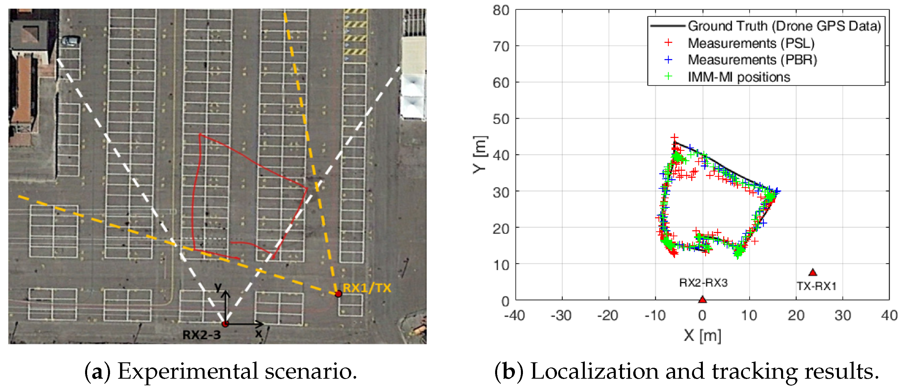
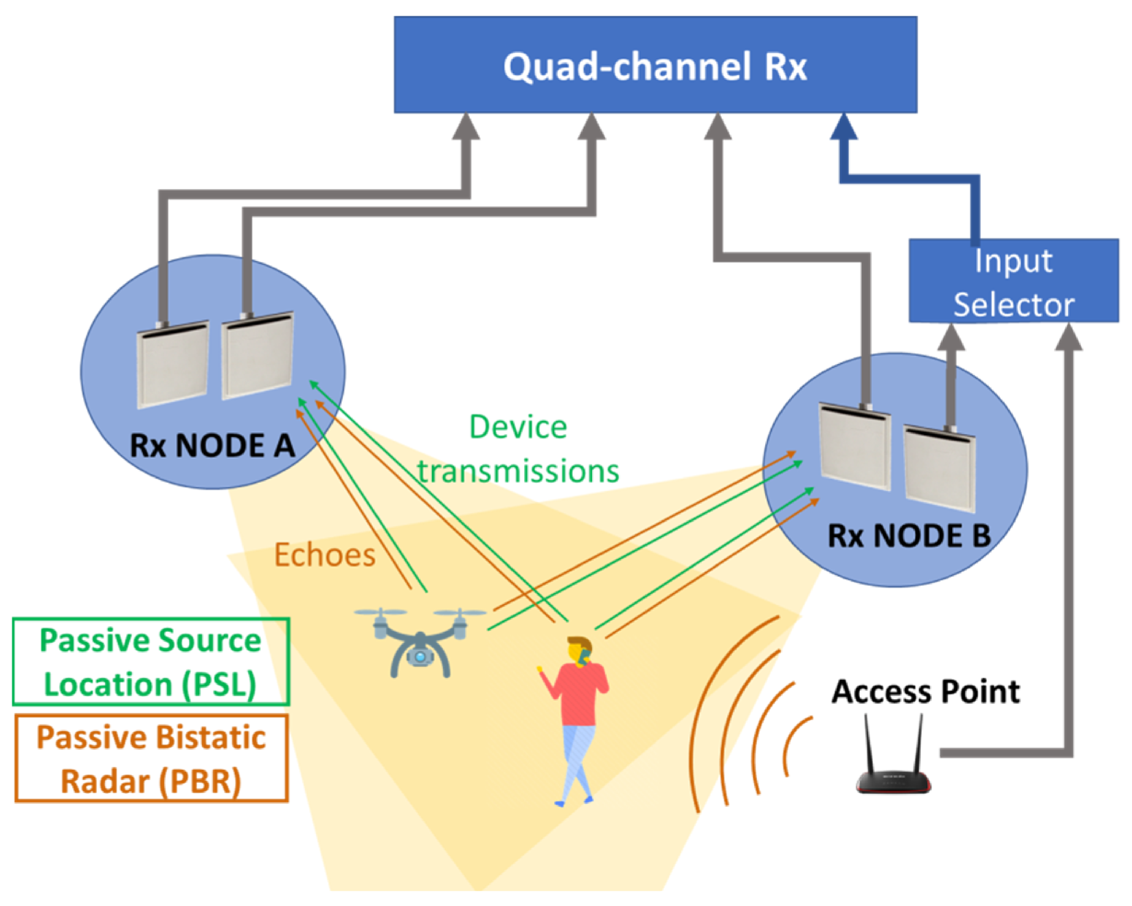
  83. Milani, I.; Bongioanni, C.; Colone, F.; Lombardo, P. Fusing Measurements from Wi-Fi Emission-Based and Passive Radar Sensors for Short-Range Surveillance. Remote Sens. 2021, 13, 3556. [Google Scholar] [CrossRef]
  84. Martelli, T.; Filippini, F.; Colone, F. Tackling the different target dynamics issues in counter drone operations using passive radar. In Proceedings of the 2020 IEEE International Radar Conference (RADAR), Washington, DC, USA, 28–30 April 2020; pp. 512–517. [Google Scholar] [CrossRef]
  85. Vorobev, E.; Veremyev, V.; Tulenkov, N. Experimental DVB-T2 Passive Radar Signatures of Small UAVs. In Proceedings of the 2019 Signal Processing Symposium (SPSympo), Krakow, Poland, 17–19 September 2019; pp. 67–70. [Google Scholar] [CrossRef]
  86. Jarabo-Amores, M.P.; Mata-Moya, D.; Gómez-del Hoyo, P.J.; Bárcena-Humanes, J.; Rosado-Sanz, J.; Rey-Maestre, N.; Rosa-Zurera, M. Drone detection feasibility with passive radars. In Proceedings of the 2018 15th European Radar Conference (EuRAD), Madrid, Spain, 26–28 September 2018; pp. 313–316. [Google Scholar] [CrossRef]
  87. Fang, G.; Yi, J.; Wan, X.; Liu, Y.; Ke, H. Experimental Research of Multistatic Passive Radar with a Single Antenna for Drone Detection. IEEE Access 2018, 6, 33542–33551. [Google Scholar] [CrossRef]
  88. Souli, N.; Kardaras, P.; Kolios, P.; Ellinas, G. Onboard Passive Radar System Implementation for Detection and Tracking of Rogue UAVs. In Proceedings of the 2023 International Conference on Unmanned Aircraft Systems (ICUAS), Warsaw, Poland, 6–9 June 2023; pp. 820–826. [Google Scholar] [CrossRef]
  89. Vinogradov, E.; Kovalev, D.A.; Pollin, S. Simulation and Detection Performance Evaluation of a UAV-mounted Passive Radar. In Proceedings of the 2018 IEEE 29th Annual International Symposium on Personal, Indoor and Mobile Radio Communications (PIMRC), Bologna, Italy, 9–12 September 2018; pp. 1185–1191. [Google Scholar] [CrossRef]
  90. Filippini, F.; Di Seglio, M.; Bongioanni, C.; Brennan, P.V.; Colone, F. OFDM based WiFi Passive Sensing: A reference-free non-coherent approach. In Proceedings of the 2023 IEEE Radar Conference (RadarConf23), San Antonio, TX, USA, 1–5 May 2023; pp. 1–6. [Google Scholar] [CrossRef]
  91. Colone, F.; Filippini, F.; Di Seglio, M.; Brennan, P.V.; Du, R.; Han, T.X. Reference-Free Amplitude-Based WiFi Passive Sensing. IEEE Trans. Aerosp. Electron. Syst. 2023, 59, 6432–6451. [Google Scholar] [CrossRef]
  92. Colone, F.; Filippini, F.; Di Seglio, M.; Chetty, K. On the Use of Reciprocal Filter Against WiFi Packets for Passive Radar. IEEE Trans. Aerosp. Electron. Syst. 2022, 58, 2746–2761. [Google Scholar] [CrossRef]
Figure 1. Outline of this paper.
Drones 09 00076 g001
Figure 2. The typical signal processing flow of a passive radar system.
Drones 09 00076 g002
Figure 3. The RD map of the classic scenario for near-range UAV detection using passive radar simulation with MF, showing a high ambiguity floor and cyclically distributed “ghost peaks”.
Drones 09 00076 g003
Figure 4. The RD map redrawn with RpF from Figure 3, effectively reducing the ambiguity floor and eliminating the “ghost peaks”, revealing a strong target.
Drones 09 00076 g004
Figure 5. The RD map after applying the ECA-B Algorithm with RpF, effectively suppressing the ambiguity floor and revealing a weak target but showing a non-ideal structure in the RD map.
Drones 09 00076 g005
Figure 6. The drone detection experiment trial in [87] uses three single-antenna receivers at different positions. Their combined coverage detects the UAV, and the highest quality reference signal is shared for signal processing, followed by trajectory fusion.
Drones 09 00076 g006
Figure 7. The results of using WiFi signal-based passive detection of UAVs without reference signals, as presented in [91], are shown in the figure. (a) The initial detection scenario with high background noise, (b) The application of traditional suppression algorithms using a reconstructed reference signal, and (c) The results achieved using the reference-free detection algorithm.
Drones 09 00076 g007
Figure 8. Experimental scenario and results for passive radar and RF joint detection in [83]. The left subfigure shows the experimental scenario setup, while the right subfigure presents the localization and tracking results of the drone on the x–y plane using sensor fusion.
Drones 09 00076 g008
Figure 9. Sketch of a system setup implementing the PBR and PSL approaches [83].
Drones 09 00076 g009
Table 1. The main types of IO used by passive radar.
Signal TypeCategoryDescriptionFrequency Range
LFMRadar signalLFM is a radar signal with a linearly varying frequency over time, often used for pulse compression to achieve better range resolution in radar applications.Depending on the radar system’s design.
DRMBroadcast RadioA digital radio system for broadcasting on longwave bands.HF
FM RadioBroadcast RadioAnalog radio broadcasting using frequency modulation.VHF
DABBroadcast RadioA digital radio standard for broadcasting in certain countries, offering clearer sound and more stations.VHF
DVB-TBroadcast TVA standard for digital terrestrial television broadcasting.UHF
GNSSSatellite-Based PositioningA global navigation satellite system used for positioning, navigation, and timing.L-band
StarLinkSatellite CommunicationA LEO satellite network providing global broadband with high speed and low latency.Ku-band, Ka-band
OneWebSatellite CommunicationA LEO satellite system offering affordable global internet coverage.Ku-band, Ka-band
InmarSatSatellite CommunicationA geostationary satellite network, with new LEO systems for enhanced global communication.L-band, Ka-band
IridiumSatellite CommunicationA LEO satellite network with pole-to-pole coverage, ideal for remote communication.L-band
WiFiWireless CommunicationA technology for local wireless data transmission.Industrial, Scientific, and Medical (ISM) Bands (2.4 GHz, 5 GHz, 6 GHz)
DVB-SSatellite TVA standard for satellite television broadcasting.C-band, Ku-band
3GMobile CommunicationThird-generation cellular network technology.UHF, L-band
4GMobile CommunicationFourth-generation cellular network technology, used for high-speed internet.UHF, L-band
5GMobile CommunicationFifth-generation cellular network technology, designed for ultra-fast internet speeds and low latency.Sub-6 GHz, mmWave
Disclaimer/Publisher’s Note: The statements, opinions and data contained in all publications are solely those of the individual author(s) and contributor(s) and not of MDPI and/or the editor(s). MDPI and/or the editor(s) disclaim responsibility for any injury to people or property resulting from any ideas, methods, instructions or products referred to in the content.

