Article

Optimization of Bandwidth Allocation and UAV Placement in Active RIS-Assisted UAV Communication Networks with Wireless Backhaul

School of Electronic Engineering, Soongsil University, Seoul 06978, Republic of Korea
*
Author to whom correspondence should be addressed.
Drones 2025, 9(2), 111; https://doi.org/10.3390/drones9020111
Submission received: 30 December 2024 / Revised: 22 January 2025 / Accepted: 29 January 2025 / Published: 2 February 2025

Abstract

:
In this paper, we present a novel design for unmanned aerial vehicle (UAV) communication networks with wireless backhaul, where an active reconfigurable intelligent surface (ARIS) is deployed to improve connections between a UAV and multiple users, while mitigating channel impairments in complex environments. The proposed design aims to maximize the achievable sum rate of all networks by jointly optimizing UAV placement; resource management strategies; transmit power allocation; and ARIS reflection coefficients, subject to backhaul constraints and power budget limitations in the ARIS system. The resulting optimization problem is highly non-convex, posing significant challenges. To tackle this, we decompose the problem into three interrelated sub-problems and apply inner approximation (IA) techniques to handle the non-convexities within each sub-problem. Moreover, a comprehensive alternating optimization framework is proposed to implement an iterative solution for the sub-problems. Simulation results demonstrate that the proposed algorithm achieves approximately 59% improvement in the average sum rate, substantially enhancing overall network reliability compared to existing benchmark schemes.

1. Introduction

Unmanned aerial vehicles (UAVs) have emerged as a transformative technology in wireless communication, offering unparalleled flexibility, cost efficiency, and adaptability to dynamic network conditions [1,2]. When employed as aerial base stations (BSs), UAVs extend network coverage, enhance connectivity, and improve communication quality [3]. By strategically positioning themselves in three-dimensional space, UAVs can establish line-of-sight (LoS) communication links, mitigate challenges for path loss, and dynamically serve users (UEs) in both urban and rural environments. However, deploying UAVs in dense urban environments presents significant challenges [4]. High-rise buildings and other structural obstacles often obstruct air-to-ground communication channels, leading to non-line-of-sight (NLoS) conditions. These conditions not only degrade signal quality through severe attenuation but also introduce multipath effects, complicating signal propagation.
To address these challenges, reconfigurable intelligent surfaces (RISs) offer a promising, cost-effective, and energy-efficient solution for enhancing wireless communication systems [5]. RISs can precisely control the amplitude and phase of incident signals to reflect and amplify wireless signals, improving signal transmission between UAVs and ground users (GUs). The advancement of RIS technology has led to extensive research into various types, including passive RIS (PRIS) [6,7], active RIS (ARIS) [8], simultaneous transmission and reflection RIS (STAR-RIS) [9], and hybrid RIS [10]. Among these, ARIS has garnered particular attention for its ability to overcome the limitations of PRIS. Unlike PRIS, which only reflects signals, ARIS incorporates power amplification within its elements, enabling both the reflection and amplification of incident signals. This makes ARIS especially effective in scenarios with significant path loss or where the transmitter and receiver are separated by long distances. In UAV communication systems, the integration of RIS provides substantial benefits by mitigating blockages caused by urban infrastructure [11,12]. ARIS, in particular, enhances system robustness and reliability by ensuring stronger, more stable links, even in complex urban environments. The combination of UAVs and RIS represents a key advancement in overcoming the challenges of urban wireless communication, unlocking new possibilities for next-generation networks.

1.1. Related Work

1.1.1. UAV Communication Systems with Wireless Backhaul

The topic of UAV communication has been extensively studied in several studies [13,14,15,16,17,18,19]. In [13], the authors explored a wireless communication system where a rotary-wing UAV is deployed as an access point (AP) to serve multiple ground nodes (GNs) using time division multiple access (TDMA). They formulated an optimization problem to minimize the UAV’s total energy consumption, encompassing both propulsion and communication energy, while satisfying the stringent requirements of all GNs. In [14], the author investigated a UAV-assisted orthogonal frequency-division multiple access (OFDMA) communication network, with the UAV functioning as a BS. The study aimed to maximize the minimum average throughput among users by jointly optimizing the UAV’s trajectory and OFDMA resource allocation while ensuring the minimum rate ratio (MRR) requirements. Considering two-way communication systems, Ref. [15] proposed UAV-assisted uplink (UL)-downlink (DL) systems employing a hybrid-mode multiple access scheme, integrating non-orthogonal multiple access (NOMA) for high average data rates and orthogonal multiple access (OMA) to support users’ instantaneous rate demands. In [16], the authors examined UAV-assisted networks enabling simultaneous UL and DL transmissions. In this system, one UAV acts as a coordinator for multiple APs, while another UAV serves as a BS to aggregate data from sensor nodes (SNs). Expanding on multi-UAVs scenarios, Ref. [17] proposed a network of UAVs providing services to GUs, with a system that effectively enhances service delivery. The authors in [18] developed strategies for user association, sub-channel allocation, and UAV trajectory in multi-UAV wireless networks. Their optimization approach aimed to maximize the minimum average rate, subject to the rate requirements of GUs, while considering spectrum reuse and managing co-channel interference management.
With advancements in storage technologies [20] and cloud computing systems [21], backhaul links to cloud networks have become increasingly important in next-generation communication systems [22]. These innovations enable efficient large-scale data processing, enhanced scalability, and the seamless integration of distributed network components, particularly in high-demand environments such as hotspots, emergency scenarios, and urban areas [23]. Motivated by these advancements, research in [24,25,26,27,28,29] has further explored UAV communication systems leveraging wireless backhaul in various contexts. Specifically, in [24], the authors investigated UAV communication networks where the UAV receives signal transmissions from a backhaul gateway and relays them to different types of users. Their goal was to maximize the minimum achievable rate for delay-tolerant users by jointly optimizing bandwidth and power allocation with UAV trajectory. In [25], the deployment of full-duplex (FD) UAVs with wireless backhaul in infrastructure-limited areas was analyzed. In [26], the UL of cell-free systems was investigated, with users connecting to UAVs that forward data to a centralized radio access network gateway via imperfect wireless fronthaul links. Moreover, the study explored multiple access technologies, including FDMA, spatial division multiple access, and hybrid schemes for fronthaul links.
The authors in [27] explored the UAV deployment as integrated access and backhaul (IAB) nodes in millimeter-wave 5G new radio networks, proposing optimization strategies for UAV-based IAB systems using deep reinforcement learning and comparing them to conventional IAB systems. In [28], the problem of minimizing UAV transmit power while ensuring users’ quality-of-service (QoS) requirements and satisfying wireless backhaul constraints was addressed. The study proposed an algorithm to jointly optimize resource allocation, UAV positioning, and transmit power for both access and backhaul links. In [29], the authors studied a DL cellular network where UAVs, powered by a wireless charging station using a save-then-transmit protocol, provide service to users through FDMA technology. Their research focused on joint optimization of user association, resource allocation, and UAV placement to maximize the DL sum rate.
While research in UAV communication has made significant progress, particularly with wireless backhaul, deploying UAV communication systems in urban environments remains a considerable challenge, emphasizing the need for innovative technologies to develop more robust and resilient solutions.

1.1.2. ARIS-Assisted UAV Communication Systems

The synergistic benefits of integrating RIS and UAV technologies have significant potential to enhance the performance of wireless networks, attracting considerable interest from researchers [30,31,32,33]. In [30], the authors explored the integration of an RIS in UAV-based OFDMA communication systems, leveraging the passive/active beamforming capabilities of the UAV’s high mobility and RIS to enhance system performance. The study formulated an optimization problem that jointly designs the RIS reflection coefficients, UAV trajectory, and resource allocation, aiming to maximize the sum rate while ensuring users’ QoS requirements are met. The study in [31] examined RIS-assisted UAV-enabled wireless-powered communication networks (WPCNs) and introduced an innovative time-switching transmission scheme to support both information transmission and energy harvesting for RIS and GUs. To optimize the achievable sum rate, the study developed optimization framework that jointly designs resource allocation, RIS phase configuration, and UAV positioning.
Expanding the applications of RIS technologies in UAV communication, Ref. [32] investigated the use of ARIS in a UAV-enabled simultaneous wireless information and power transfer system. The study aimed to minimize the total energy consumption of the UAV while ensuring that all users meet their energy harvesting and information transmission requirements. It also highlighted the significant advantages of ARIS over conventional PRIS, demonstrating its superior performance and energy efficiency. In [33], a UAV DL communication system for multiple users utilizing a hybrid active-passive RIS was analyzed. The study aimed to maximize the minimum rate for each user by jointly optimizing the UAV’s location/trajectory, beamforming, and RIS reflection coefficients. This optimization framework was applied to both static and mobile UAV network configurations.
However, the aforementioned studies primarily focused on UAV communication systems utilizing RIS and did not consider the potential for end-to-end service provision with wireless backhaul. Recent works integrating RIS into UAV DL networks with backhaul links have explored various scenarios [34,35,36]. In [34], the authors considered UAV-assisted IAB technology as the end-to-end server provider, where UAV and PRIS were deployed to support user ULs. Focusing on end-to-end energy efficiency, the study optimized the phase shifts of RIS elements, bandwidth allocation, and the transmit power of both the user and UAV. In [35], the authors deployed PRIS in the UAV wireless network to support both wireless access and backhaul links. The study aimed to maximize the sum rate across all GUs by optimizing UAV placement, PRIS phase shifts, and sub-channel assignments while adhering to wireless backhaul constraints.
In [36], a different cutting-edge technology for backhaul links was investigated, where the authors examined a PRIS-assisted UAV DL network enabled by simultaneous lightwave information and power transfer via free-space optics backhaul. This study aimed to maximize the minimum rate by optimizing the PRIS reflection coefficients, transmitting power at the optical ground station (GS), and the power-splitting ratio. Most existing studies have predominantly focused on deploying PRIS in these systems. However, the use of ARIS, particularly its ability to amplify signals, represents a significant advancement. The integration of ARIS into UAV DL networks with backhaul links, combined with efficient resource allocation strategies, remains a novel and underexplored area of research.

1.2. Contributions and Outline

This study investigates a UAV-enabled DL communication system supported by a wireless backhaul and assisted by an ARIS. The primary objective is to maximize the sum achievable data rate across all users. To achieve this, we jointly optimize the ARIS reflection coefficients, UAV placement, transmit power allocation, and resource management, while adhering to stringent constraints, including users’ QoS, the ARIS power budget, and wireless backhaul limitations. The main contributions of this study are as follows:
  • We introduce a novel communication architecture that integrates UAVs with ARIS in a wireless backhaul system. This framework establishes an optimized approach to improving the efficiency and capacity of DL communications.
  • We formulate a comprehensive optimization problem optimized approach to the sum rate across all users in the DL network. This problem involves the intricate interplay of UAV placement, transmit power, ARIS reflection coefficients, and resource allocation strategies, resulting in a highly non-convex and computationally challenging problem.
  • To address this complexity, we adopt the block coordinate ascent (BCA) method to decompose the primary problem into three interrelated sub-problems and leverage inner approximation (IA) techniques to effectively handle the non-convexity inherent in each sub-problem. Additionally, a holistic algorithm based on the alternating optimization (AO) framework is developed to solve these sub-problems iteratively.
  • Through extensive simulations, we validate the performance of the proposed system, demonstrating its superiority over traditional methods. The results reveal that our approach significantly outperforms systems utilizing PRIS or fixed UAV placements, enhancing network performance and ensuring robust connectivity between the UAV and users through ARIS.
The remainder of this paper is organized as follows. Section 2 outlines the system model and formulates the optimization problem. Section 3 presents the iterative algorithm used to solve the sub-problems. Section 4 discusses the numerical results, highlighting the performance improvements of the proposed framework. Finally, Section 5 concludes the paper and provides insights into future research directions.
Notation: In this work, scalars are denoted by lower-case letters, and vectors and matrices are denoted by bold-face letters. ( · ) T and ( · ) H denote the transpose and conjugate transpose of a matrix or vector, respectively. The absolute value and norm products are represented by | · | and · . I N denote the identity matrix of size N × N , and sgn ( x ) returns the sign of the real number x.

2. System Model and Problem Formulation

We consider an ARIS-assisted UAV communication network utilizing a wireless backhaul link, where the UAV acts as a BS, as illustrated in Figure 1. The UAV serves a set of UEs, denoted by K = { 1 , 2 , , K } , using a single antenna. An ARIS with N elements is deployed within the UAV network to improve system performance, with the set of ARIS element indices represented as N = { 1 , 2 , , N } . Geometrically, the UAV is positioned in three-dimensional space at r u a v = [ x u , y u , h u ] , covering a wide area and operating at a distance from the GS, located at r g s = [ x g s , y g s , h g s ] . The ARIS, located at r a r i s = [ x r , y r , h r ] , is strategically deployed to assist the UAV in serving the UEs.
In the proposed system, the communication process takes place within a transmission time block, denoted by T max , assuming T max = 1 as in [37]. This time block is divided into two phases as follows: In Phase I, backhaul transmission occurs over T max τ , utilizing the entire system bandwidth, B, to facilitate efficient data transfer between the GS and the UAV. In Phase II, the access link operates over T max ( 1 τ ) , where the UAV decodes the signals received from the GS and forwards them to the UEs using the FDMA protocol. For the access link in Phase II, the total system bandwidth, B, is allocated among the UEs. The bandwidth fraction allocated to the k-th UE is denoted as φ k , satisfying k K φ k 1 . This two-phase transmission framework aligns with methodologies described in prior works, such as [38]. Our resource allocation strategy integrates bandwidth allocation, time division, and power allocation. Bandwidth is shared between backhaul and fronthaul, with fronthaul bandwidth shared among users. Time division minimizes interference between fronthaul and backhaul transmissions, and power allocation optimizes UAV transmission power, enhancing efficiency and balancing resource consumption with data rate performance.

2.1. Channel Model

In this subsection, we present the channel model for the ARIS-assisted UAV communication system using a wireless backhaul link. The channel model of the proposed system consists of two main components as follows: the backhaul link and the access link.

2.1.1. Backhaul Link

We model the backhaul link as a LoS channel. Using the free-space path loss model, the channel gain for the backhaul link is given as [39]
g B = ρ 0 r g s r u a v 2 ,
where ρ 0 is the path loss at the reference distance of 1 m.

2.1.2. Access Link

We assume that all DL communication channels experience frequency-flat fading. Therefore, the channel model includes both direct and reflecting channels. The direct channel for UAV-UEs is denoted by h u , k C 1 × 1 , the reflecting channel for UAV-ARIS is represented by G u , r C 1 × N , and the reflecting channel for ARIS-UEs is denoted by h r , k C N × 1 . In our system, we model the UAV-UE channel as the Rayleigh fading, while the UAV-ARIS and the ARIS-UEs channels follow the Rician fading mode. Considering the urban environment of the study, where tall buildings frequently obstruct the line-of-sight (LoS) links between the UAV and UEs, Rayleigh fading is a realistic and appropriate assumption for characterizing UAV-UE channels [33,40]. In contrast, the Rician fading model is applied to the UAV-ARIS and ARIS-UE channels because both the UAV and ARIS are positioned at elevated heights. This placement ensures the presence of a strong LoS component in addition to scattered components, making the Rician fading model well-suited for these channels [41]. By modeling both UAV-ARIS and ARIS-UE channels as Rician fading, we account for the potential coexistence of LoS and NLoS components, capturing a more general representation of the channel conditions in the urban environment.
For the UAV-ARIS channel, the channel gain is expressed as
G u , r = ρ 0 r u a v r a r i s ϵ 1 ( k k + 1 G ¯ ¯ u , r + 1 k + 1 G ¯ u , r ) ,
where ϵ 1 represents the path loss exponent for the UAV-ARIS link, and G ¯ u , r C N ( 0 , 1 ) represents the NLoS component of the UAV-ARIS link. Moreover, G ¯ ¯ u , r = [ 1 , e j 2 π d λ c o s ( ϕ ) , , e j 2 π d ( N 1 ) λ c o s ( ϕ ) ] T represents the deterministic LoS component, where d is the unit spacing of the RIS elements, λ is the carrier wavelength, and ϕ is the angle of arrival (AoA) of the UAV-ARIS link. For the ARIS-UE k link, the channel gain is represented as
h r , k = ρ 0 r a r i s r u , k ϵ 2 ( k k + 1 h ¯ ¯ r , k + 1 k + 1 h ¯ r , k ) ,
where ϵ 2 denotes the path loss exponent for the ARIS-UEs link, and h ¯ r , k C N ( 0 , 1 ) denotes the NLoS components. The deterministic component of the ARIS-UE k link is given by h ¯ ¯ r , k = [ 1 , e j 2 π d λ c o s ( ψ ) , , e j 2 π d ( N 1 ) λ c o s ( ψ ) ] , where ψ denotes the angle of departure (AoD) from the ARIS to UE k . For the UAV-UE k link, which follows the Rayleigh fading model, the channel gain is given as
h u , k = ρ 0 r u a v r u , k ϵ 0 2 h ¯ u , k ,
where ϵ 0 is the path loss exponent for the UAV-UEs link, h u , k C N ( 0 , 1 ) represents the NLoS components of the UAV-UE k channel.

2.2. Signal Model

At the GS, the signal is transmitted to the UAV via a wireless backhaul link during Phase I. The UAV decodes the signal and forwards it to UEs in the subsequent phase. The received signal at the UAV over the wireless backhaul at the UAV can be modeled as
y b = P B g B x b + n b ,
where P B is the transmitted power at the GS for the wireless backhaul, x b = [ x 1 , , x K ] is the transmitted signal vector, and n b represents the noise vector. Based on (5), the signal-to-noise ratio (SNR) of the wireless backhaul is computed as
γ B = P B g B σ 2 .
The achievable rate of the backhaul link (in nats/s) is then expressed as
R B = τ B ln ( 1 + γ B ) .
During Phase II, the signal is transmitted to the UEs through the UAV with the assistance of the ARIS. The ARIS dynamically adjusts the signal using its reflection coefficients, which are implemented with reflection-type amplifiers. As a result, the received signal at UE k is given as
y k = p k ( h u , k + h r , k H Φ G u , r ) x k + h r , k H Φ n r + n k , k K ,
where p k denotes the transmit power from the UAV to UE k , n k CN ( 0 , σ 2 ) represents the additive white Gaussian noise (AWGN) at UE k , and n r CN ( 0 , σ r 2 I N ) is the thermal noise of the ARIS elements. The matrix Φ = diag ( α ) C N × N represents the ARIS refection coefficients, where α = [ α 1 , α 2 , . . . , α N ] and each element α n is expressed as α n = | α n | e j θ n , with | α n | a max . Here, a max represents the maximum gain achievable by an active load, which can reach up to 40 dB when implemented using reflection amplifiers [33,42]. Using (8), the SNR of UE k is given as
γ A , k = p k | ( h u , k + h r , k H Φ G u , r ) | 2 h r , k H Φ 2 σ r 2 + σ k 2 .
The corresponding achievable rate of UE k (in nats/s) can be expressed as
R A , k = ( 1 τ ) φ k B ln ( 1 + γ A , k ) , k K .

2.3. Problem Formulation

Our objective is to maximize the sum achievable rate for all UEs in the ARIS-assisted UAV communication network by optimizing the UAV placement, resource allocation, and the ARIS reflection coefficients. The optimization problem is formulated as
max p , φ , r u a v , Φ , τ k K R A , k
s . t . 0 k = 1 K p k P max u a v ,
0 < φ k < 1 , k K ,
k K φ k 1 ,
0 τ 1 ,
| α n | a max , n N ,
n N | α n | 2 ( σ r 2 + | G n | 2 k = 1 K p k ) p max r i s ,
k K R A , k R B ,
R A , k R Q o S , k K ,
where p = { p k K } 1 × K and φ = { φ k K } 1 × K represent the optimization variables for transmit power and bandwidth allocation, respectively. Constraint (11b) ensures that the total transmit power allocated to all UEs does not exceed the UAV’s maximum power budget, p max u a v . Constraints (11c)–(11e) define the requirements for bandwidth and time allocation, ensuring feasible resource allocation. Constraint (11c) ensures that each UE is allocated a portion of the total available bandwidth within the feasible range. Additionally, constraint (11d) guarantees that the total bandwidth allocated to all UEs does not exceed the available bandwidth. Constraint (11e) ensures that the time allocation factor τ remains within a feasible range from 0 to 1. Constraints (11f)–(11g) impose limitations on the maximum gain of the n-th ARIS element and the ARIS’s total power consumption, ensuring it does not exceed the maximum power budget, p max r i s . Here, G n denotes the n-th element of the channel G u , r . Constraint (11h) ensures the sum rate of all UEs does not exceed the backhaul link capacity R B and constraint (11i) guarantees that the achievable rate for each UE satisfies its individual QoS requirement, R Q o S .

3. Proposed Alternating Optimization Algorithm

The original optimization problem is challenging to solve directly due to the intricate coupling of the variables, particularly Φ and r u a v . To simplify, we introduce new auxiliary variables t = { t k } k K and ω = { ω k } k K . Using these variables, the problem in (11) can be reformulated as
max p , φ , r u a v , Φ , τ , t , ω k K t k
s . t . ( 1 τ ) φ k B ln ( 1 + 1 ω k ) t k , k K ,
γ A , k 1 ω k , k K ,
t k R Q o S , k K ,
(11b)–(11i).
To solve the reformulated problem, we adopt the BCA and IA method-based AO framework to develop an iterative algorithm. In this approach, the BCA method decomposes the original problem into sub-problems. To handle the non-convexity of each sub-problem, efficient approximation functions are derived using the IA method. The iterative algorithm alternately optimizes blocks of variables, and this process continues until convergence, ultimately leading to locally optimal solutions for the problem. Before solving each sub-problem, we employ IA for the following functions:
  • For the quadratic function f q ( m , n ) m n 2 , m , n C D , D R , D 1 , a lower bound at iteration ( i + 1 ) -th can be derived using [33] as
    f q ( m , n ) 2 ( m ( i ) n ( i ) ) T ( m m ( i ) ) + m ( i ) n ( i ) 2 = f q ( i ) ( m , n ) .
  • For the power function f p ( m , n ) m n , m R + + , n < 0 or n 1 , an upper bound at iteration ( i + 1 ) -th is given as [43]
    f p ( m , n ) ( n 1 ) ( m ( i ) ) n + n ( m ( i ) ) n 1 m : = f p ( i ) ( m , n ) .
  • For the bilinear function f b ( m , n , 1 ) m n , ( m , n ) R + + 2 , known as the multiplicative function, an upper bound at iteration ( i + 1 ) -th can be expressed as [33]
    f b ( m , n , 1 ) n ( i ) 2 m ( i ) m 2 + m ( i ) 2 n ( i ) n 2 : = f b ( i ) ( m , n , 1 ) .
  • For the bilinear function f b ( m , n , 1 ) m n , ( m , n ) R + + 2 , an upper bound at iteration ( i + 1 ) -th is derived as [33]
    f b ( m , n , 1 ) 0.25 ( m n ) 2 + 0.25 ( m ( i ) + n ( i ) ) 2 0.5 ( m ( i ) + n ( i ) ) ( m + n ) : = f b ( i ) ( m , n , 1 ) .
The subsequent subsections detail how the sub-problems for transmit power, resource allocation, AIRS reflection coefficients, and UAV placement are approximated and solved using the IA-based functions outlined in (13)–(16).

3.1. Optimization of p , φ , and τ with Given r ¯ u a v and Φ ¯

The sub-problem of optimizing the transmit power and resource allocation with given ARIS reflection coefficients ( Φ ¯ ) and UAV placement ( r ¯ u a v ) can be reformulated as
max p , φ , τ , t , ω k K t k
s . t . ( 1 τ ) φ k B ln ( 1 + 1 ω k ) t k , k K ,
a k p k 1 ω k , k K ,
k = 1 K ( 1 τ ) φ k B ln ( 1 + a k p k ) τ B ln ( 1 + γ B ) ,
(11b)–(11e), (11g), (12d),
where a k = | ( h u , k + h r , k H Φ ¯ G u , r ) | 2 h r , k H Φ ¯ 2 σ r 2 + σ k 2 , k K . Since constraints (17b) and (17d) are non-convex, the problem remains non-convex. To address this, we first introduce slack variables ϑ { ϑ k } k K to create a lower bound of ( 1 τ ) φ k , satisfying
1 ϑ k ( 1 τ ) φ k , k K .
However, (18) is non-convex. Additional slack variables δ { δ k } k K are introduced, satisfying
1 ϑ k δ k 2 , k K ,
δ k 2 ( 1 τ ) φ k , k K .
Using the quadratic lower-bound approximation in (13), (19) can inner-approximated as
1 ϑ k f q ( i ) ( δ k , 0 ) f q ( δ k , 0 ) = δ k 2 , k K .
For constraint (17b), we approximate ln ( 1 + 1 / ω k ) / ϑ k at a feasible point ( ω k ( i ) , ϑ k ( i ) ) as follows ([44], Equation (46)):
1 ϑ k ln ( 1 + 1 ω k ) A 0 , k ( i ) A 1 , k ( i ) ω k A 2 , k ( i ) ϑ k ,
where
A 0 , k ( i ) = 2 ln ( 1 + 1 / ω k ( i ) ) ϑ k ( i ) + 1 ϑ k ( i ) ( ω k ( i ) + 1 ) , A 1 , k ( i ) = 1 ϑ k ( i ) ω k ( i ) ( ω k ( i ) + 1 ) , A 2 , k ( i ) = ln ( 1 + 1 / ω k ( i ) ) ( ϑ k ( i ) ) 2 , ϑ k ( i ) 0 , ω k ( i ) 0 .
Thus, constraint (17b) can be approximated as
B ( A 0 , k ( i ) A 1 , k ( i ) ω k A 2 , k ( i ) ϑ k ) t k , k K .
To approximate (17d), slack variables u { u k } k K are introduced, satisfying
( 1 τ ) φ k u k , k K .
Using the bilinear upper-bound approximation in (15) with m = 1 τ and n k = φ k , ( 1 τ ) φ k , k K in (24) can be approximated as
f b ( 1 τ , φ k , 1 ) ( 1 τ ) φ k f b ( i ) ( 1 τ , φ k , 1 ) u k , k K .
Using inequality [36], an upper bound of ln ( 1 + a k p k ) , a k p k > 0 is given as
ln ( 1 + a k p k ) a ( a k p k ( i ) ) + b ( a k p k ( i ) ) a k p k ,
where
a ( a k p k ( i ) ) ln ( 1 + a k p k ( i ) ) a k p k ( i ) 1 + a k p k ( i ) , b ( a k p k ( i ) ) 1 1 + a k p k ( i ) .
We can approximate (17d) as
k = 1 K u k ( a ( a k p k ( i ) ) + b ( a k p k ( i ) ) a k p k ) τ ln ( 1 + γ B ) .
However, (27) is still non-convex. By applying (15) with m = u k > 0 and n = a ( a k p k ( i ) ) + b ( a k p k ( i ) ) a k p k , k K , (27) is approximated as
k = 1 K f b ( u k , a ( a k p k ( i ) ) + b ( a k p k ( i ) ) a k p k , 1 ) k = 1 K f b ( i ) ( u k , a ( a k p k ( i ) ) + b ( a k p k ( i ) ) a k p k , 1 ) τ ln ( 1 + γ B ) .
In summary, the convex approximation for (17) at iteration ( i + 1 ) -th is formulated as
max p , φ , τ t , ω , U k K t k
s . t . ( 11 b ) ( 11 e ) , ( 11 g ) , ( 12 d ) , ( 17 c ) , ( 19 ) , ( 20 ) , ( 23 ) , ( 25 ) , ( 28 ) ,
where U { ϑ , δ , u } . In (29), all constraints are linear and/or conic, which satisfies the Karush-Kuhn-Tucker (KKT) conditions [45]. Consequently, it can be solved using the MOSEK solver and YALMIP toolbox.

3.2. Optimization of Φ with Given p ¯ , φ ¯ , τ ¯ , and r ¯ u a v

In this subsection, we aim to optimize the ARIS reflection Φ using the given resource allocation and UAV placement ( p ¯ , φ ¯ , τ ¯ , r ¯ u a v ). The sub-problem can be expressed as
max Φ , t , ω k K t k
s . t . ( 1 τ ¯ ) φ ¯ k B ln ( 1 + 1 ω k ) t k , k K ,
γ A , k 1 ω k , k K ,
k = 1 K ( 1 τ ¯ ) φ ¯ k B ln ( 1 + γ A , k ) τ ¯ B ln ( 1 + γ B ) ,
(11f)–(11g), (12d).
Constraints (30b)–(30d) are non-convex. First, constraint (30c) can be rewritten as
p ¯ k | h u , k + h r , k H Φ G u , r | 2 h r , k H Φ 2 σ r 2 + σ 2 1 ω k , k K .
Using the approximation in (13), the term h k ( Φ ) | h u , k + h r , k H Φ G u , r | 2 is lower-bounded as
h k ( Φ ) f q ( i ) ( h k ( Φ ) , 0 ) , k K .
Hence, constraint (30c) is reformulated in second-order cone (SOC) form as follows:
p ¯ k f q ( i ) ( h k ( Φ ) , 0 ) ω k h r , k H Φ 2 σ r 2 + σ 2 , k K .
We now address constraint (30b) by approximating the function ln ( 1 + 1 / ω k ) . As shown in [46], using a first-order Taylor expansion, a lower bound of ln ( 1 + 1 / ω k ) , ω k > 0 can be approximated at a given point ω k ( i ) as
ln ( 1 + 1 / ω k ) Θ ( ω k ( i ) ) Ξ ( ω k ( i ) ) ω k ,
where
Θ ( ω k ( i ) ) ln ( 1 + 1 / ω k ( i ) ) + 1 / ( ω k ( i ) + 1 ) , Ξ ( ω k ( i ) ) 1 / ω k ( i ) ( ω k ( i ) + 1 ) .
Thus, the constraint (30b) becomes
( 1 τ ¯ ) φ ¯ k B ( Θ ( ω k ( i ) ) Ξ ( ω k ( i ) ) ω k ) t k , k K .
To address the non-convexity of ln ( 1 + γ k , A ) in (30d), we utilize the method described in (26) as follows:
ln ( 1 + γ A , k ) a ( γ A , k ( i ) ) + b ( γ A , k ( i ) ) γ A , k = a ( γ A , k ( i ) ) + b ( γ A , k ( i ) ) p ¯ k | ( h u , k + h r , k H Φ G u , r ) | 2 h r , k H Φ 2 σ r 2 + σ 2 .
We introduce slack variables η { η k } k K , such that
h r , k H Φ 2 σ r 2 + σ 2 η k , k K .
Using H r , k = diag { h r , k H } , we can compute a lower bound of H r , k α T 2 as
H r , k α T 2 f q ( i ) ( H r , k α T , 0 ) .
Thus, constraint (37) can be rewritten as
f q ( i ) ( H r , k α T , 0 ) σ r 2 + σ 2 η k , k K .
We also introduce slack variables ζ k { ζ k } k K , which satisfies the following SOC constraint:
ζ k a ( γ k ( i ) ) + b ( γ k ( i ) ) p ¯ k | ( h u , k + h r , k H Φ G u , r ) | 2 η k , k K .
Consequently, we can rewrite constraint (30d) as
k = 1 K ζ k τ ¯ ln ( 1 + γ B ) .
Finally, the convex approximation of the sub-problem (30) at iteration ( i + 1 ) is given as
max Φ , t , ω , W k K t k
s . t . ( 11 f ) ( 11 g ) , ( 12 d ) ( 33 ) , ( 35 ) , ( 39 ) , ( 40 ) , ( 41 ) ,
where W { η , ζ } . It is straightforward to verify that sub-problem (42) is convex. To solve this convex optimization problem, we utilize the YALMIP toolbox [45], a widely used MATLAB-based framework for convex optimization, ensuring computational efficiency and reliability.

3.3. Optimization of r u a v with Given p ¯ , φ ¯ , τ ¯ , and Φ ¯

This subsection focuses on optimizing the UAV placement ( r u a v ) with the given resource allocation and ARIS reflection coefficients ( p ¯ , φ ¯ , τ ¯ , Φ ¯ ). Consequently, the problem in (12) for optimizing UAV placement is reformulated as
max r u a v , t , ω k K t k
s . t . ( 1 τ ¯ ) φ ¯ k B ln ( 1 + 1 ω k ) t k , k K ,
γ A , k 1 ω k , k K ,
k = 1 K ( 1 τ ¯ ) φ ¯ k B ln ( 1 + γ A , k ) τ ¯ B ln ( 1 + γ B ) ,
(11g), (12d).
To address this sub-problem, we first rewrite the expression for R A , k to highlight its dependence on r u a v . Specifically, p ¯ k | h u , k + h r , k H Φ ¯ G u , r | 2 is rewritten as
p ¯ k | h u , k + h r , k H Φ ¯ G u , r | 2 = p ¯ k | h u , k | 2 + p ¯ k | h r , k H Φ ¯ G u , r | 2 + 2 p ¯ k ( h u , k H h r , k H Φ ¯ G u , r ) = c 0 , k r u a v r u , k ϵ 0 + c 1 , k r u a v r a r i s ϵ 1 + c 0 , 2 r u a v r u , k ϵ 0 / 2 r u a v r a r i s ϵ 0 / 2 ,
where c 0 , k = p ¯ k | h ¯ u , k | 2 ρ 0 , c 1 , k = p k | h r , k H Φ ¯ G 0 | 2 ρ 0 , c 2 , k = 2 p k ( h ¯ u , k H h r , k H Φ ¯ G 0 ) ρ 0 , and G 0 k k + 1 G ¯ ¯ u , r + 1 k + 1 G ¯ u , r . Here, c 0 , k , c 1 , k > 0 and c 2 , k can be either positive or negative. To convexify (43c), the norm components in (44) should be addressed. First, a set of slack variables r ̲ 0 { r ̲ 0 , k } k K , r ̲ 1 , r ¯ 0 { r ¯ 0 , k } k K , r ¯ 1 , r 2 are introduced, satisfying the following power cone constraints:
r ̲ 0 , k r u a v r u , k ϵ 0 / 2 , k K ,
r ̲ 1 r u a v r a r i s ϵ 1 / 2 ,
r ¯ 0 , k r u a v r u , k ϵ 0 / 2 , k K ,
r ¯ 1 r u a v r a r i s ϵ 1 / 2 ,
r 2 r u a v r g s 2 .
Additional slack variables ϱ ̲ { ϱ ̲ k } k K , ϱ ¯ { ϱ ¯ k } k K are introduced, which satisfy
ϱ ̲ k c 0 , k r ̲ 0 . k 2 + c 1 , k r ̲ 1 2 + | c 2 , k | r ̲ 0 , k r ̲ 1 , if c 2 , k > 0 c 0 , k r ̲ 0 . k 2 + c 1 , k r ̲ 1 2 | c 2 , k | r ¯ 0 , k r ¯ 1 , otherwise , k K ,
ϱ ¯ k c 0 , k r ¯ 0 . k 2 + c 1 , k r ¯ 1 2 + | c 2 , k | r ¯ 0 , k r ¯ 1 , if c 2 , k > 0 c 0 , k r ¯ 0 . k 2 + c 1 , k r ¯ 1 2 | c 2 , k | r ̲ 0 , k r ̲ 1 , otherwise , k K .
Using (13)–(16), constraints (45a)–(46b) can be approximated as
r u a v r u , k + f p ( i ) ( r ̲ 0 , k ; 2 / ϵ 0 ) 0 , k K ,
r u a v r a r i s + f p ( i ) ( r ̲ 1 ; 2 / ϵ 1 ) 0 ,
f q ( i ) ( r u a v ; r u , k ) 1 / f p ( i ) ( r ¯ 0 , k ; 4 / ϵ 0 ) , k K ,
f q ( i ) ( r u a v ; r a r i s ) 1 / f p ( i ) ( r ¯ 1 ; 4 / ϵ 1 ) ,
r u a v r g s + f p ( i ) ( r 2 ; 1 / 2 ) 0 ,
ϱ ̲ k + c 0 , k f q ( i ) ( r ̲ 0 , k ; 0 ) + c 1 , k f q ( i ) ( r ̲ 1 ; 0 ) + f b ( i ) ( r ̲ 0 , k ; r ̲ 1 ; s g n ( c 2 , k ) ) 0 , k K ,
ϱ ¯ k c 0 , k r ¯ 0 , k 2 + c 1 , k r ¯ 1 2 + f b ( i ) ( r ¯ 0 , k , r ¯ 1 ; s g n ( c 2 , k ) ) , k K .
Using (47a), (47b), (47f), constraint (43c) can be rewritten as
ϱ ̲ k ω k σ k 2 , k K ,
with σ k 2 = h r , k H Φ ¯ 2 σ r 2 + σ 2 , k K . To deal with the non-convex term ln ( 1 + 1 / ω k ) in (43b), we employ a similar procedure introduced in the previous subsection to seek the linear lower bound for it. Thereby, constraint (43b) can be rewritten as constraint (35).
For constraint (43d), using (47c), (47d), and (47g), an upper bound of R A , k can be expressed as
R A , k ( 1 τ ¯ ) φ ¯ k B ln ( 1 + ϱ ¯ k / σ k 2 ) , k K .
As the function ln ( 1 + ϱ ¯ k / σ k 2 ) is concave, we can find an upper bound of the function using (26) as
ln ( 1 + ϱ ¯ k / σ k 2 ) a ( ϱ ¯ k ( i ) ) + b ( ϱ ¯ k ( i ) ) ( ϱ ¯ k / σ k 2 ) , k K .
Using (47e), R B can be approximated as R B τ B ln ( 1 + ( P B ρ 0 r 2 ) / σ 2 ) , which is still non-convex. By introducing slack variable μ , we have the following constraint:
P B ρ 0 r 2 σ 2 1 μ .
Similar to (34), a lower bound of the function ln ( 1 + 1 / μ ) can be found as
ln ( 1 + 1 / μ ) Θ ( μ ( i ) ) Ξ ( μ ( i ) ) μ , μ , μ ( i ) > 0 .
As a result, the constraint (43d) can be rewritten in convex form as
k K ( 1 τ ¯ ) φ ¯ k [ a ( s k ( i ) ) + b ( s k ( i ) ) s k ] τ ¯ [ Θ ( μ ( i ) ) Ξ ( μ ( i ) ) μ ] .
For constraint (11g), we first rewrite | G n | 2 as
| G n | 2 = c 3 , n ( r u a v r a r i s ϵ 1 / 2 ) 2 ,
where c 3 , n | G 0 , n | 2 ρ 0 and G 0 , n is the n-th element of G 0 . Based on (45d) and (54), we can rewrite (11g) as
n N | α n | 2 ( σ r 2 + c 3 , n r ¯ 1 2 k = 1 K p ¯ k ) p max r i s .
Consequently, the convex approximation of the sub-problem (43) at iteration ( i + 1 ) can be expressed as
max r u a v , t , ω , R k K t k
s . t . ( 12 d ) , ( 47 a ) ( 47 g ) , ( 48 ) , ( 35 ) , ( 51 ) , ( 53 ) , ( 55 ) ,
where R { r ̲ 0 , r ̲ 1 , r ¯ 0 , r ¯ 1 , r 2 , ϱ ̲ , ϱ ¯ , μ } . Note that all constraints in (56) are linear, quadratic, or have a SOC form, ensuring compliance with the KKT conditions [45].

3.4. Generation of Initial Points

To execute (29), (42), and (56), feasible initial points ( τ , p , φ , Φ , r u a v ) ( 0 ) are necessary. In this study, the initial values for resource allocation, ARIS reflection coefficients, and UAV placement are derived while ensuring compliance with the QoS requirements and backhaul constraints. To facilitate this process, we introduce a slack variable z { z k } k K , which satisfies t k R Q o S z k and R B k K R A , k z k . The following sub-problems are then solved to determine the initial points for (29), (42), and (56):
  • Generation of an initial point ( τ ( 0 ) , p ( 0 ) , φ ( 0 ) ) :
    max τ , p , φ , t , ω , U , z k K z k
    s . t . τ ln ( 1 + γ B ) k = 1 K f m ( i ) ( u k , a ( a k p k ( i ) ) + b ( a k p k ( i ) ) a k p k ) z k ,
    t k R Q o S z k ,
    (11b)–(11e), (11g), (17c), (20), (19), (23), (25).
  • Generation of an initial point Φ ( 0 ) :
    max Φ , t , ω , W , z k K z k
    s . t . τ ¯ ln ( 1 + γ B ) k = 1 K ζ k z k ,
    t k R Q o S z k ,
    (11f)–(11g), (32), (33), (35), (39), (40).
  • Generation of an initial point r u a v ( 0 ) :
    max r u a v , t , ω , R , z k K z k
    s . t . τ ¯ [ Θ ( μ ( i ) ) Ξ ( μ ( i ) ) μ ] k K ( 1 τ ¯ ) φ ¯ k [ a ( s k ( i ) ) + b ( s k ( i ) ) s k ] z k ,
    t k R Q o S z k ,
    (47a)–(47g), (48), (51), (53), (55).
An initial point for (57), (58), and (59) is considered valid when k K z k approaches zero. Finally, the overall procedure for obtaining the initial points and solving the optimization problems is summarized in Algorithm 1.
Algorithm 1 Proposed algorithm to solve the problem (11)
Initialization:
  1:
Randomly initialize ( p , φ , τ , Φ , r u a v ) such that the equality constraints in (11b)–(11f) are satisfied.
  2:
Solve (57) with the given Φ and r u a v to obtain updated solutions p , φ , τ . Update p = p , φ = φ , τ = τ .
  3:
Solve (58) with the updated p , φ , τ , and r u a v to obtain solution Φ . Update Φ = Φ .
  4:
Solve (58) with the updated p , φ , τ , and Φ to obtain solution r u a v . Update r u a v = r u a v .
  5:
Set i = 0 and initialize ( p , φ , τ , Φ , r u a v ) 0 = ( p , φ , τ , Φ , r u a v ) .
Main Iterative Process:
  6:
Repeat
  7:
    Solve problem (29) with the current Φ ( i ) and r u a v ( i ) to obtain solutions p * , φ * , τ * , and U * . Update p ( i + 1 ) = p * , φ ( i + 1 ) = φ * , τ ( i + 1 ) = τ * , and U ( i + 1 ) = U * .
  8:
    Solve problem (42) with the current r u a v ( i ) , p ( i ) , φ ( i ) , and τ ( i ) to obtain solutions Φ * and W * . Update Φ ( i + 1 ) = Φ * and W ( i + 1 ) = W * .
  9:
    Solve problem (56) with the current Φ ( i ) , p ( i ) , φ ( i ) , and τ ( i ) to obtain solutions r u a v * and R * . Update r u a v ( i + 1 ) = r u a v * and R ( i + 1 ) = R * .
10:
    Set i = i + 1 .
11:
Until Convergence

3.5. Overall Algorithm

In this subsection, we analyze the computational complexity of the proposed algorithm. The joint optimization of resource allocation, ARIS reflection coefficients, and UAV placement is outlined in Algorithm 1. Initially, feasible solutions for ( p , φ , τ , Φ , r u a v , t , ω , U , W , R ) ( 0 ) are generated in Steps 1–5. Following this, in Steps 6–11, sub-problems (29), (42), and (56) are alternately and iteratively solved until convergence. The primary computational cost of Algorithm 1 arises from solving the sub-problems, each formulated as a convex optimization problem with specific constraints and variables. According to [47], the complexity for each iteration of a convex program is given by O ( p j 2 q j 2.5 + q j 3.5 ) , where p j and q j denote the number of variables and SOC/quadratic/linear constraints in the j-th sub-problem. Here, j { 1 , 2 , 3 } refers to sub-problems (29), (42), and (56), respectively. Therefore, the total complexity of Algorithm 1 is given by C = O ( I j = 1 3 ( p j 2 q j 2.5 + q j 3.5 ) ) , where I denotes the number of iterations required for the algorithm to converge. A detailed breakdown of the computational complexity for each sub-problem and the overall algorithm is summarized in Table 1.
In Algorithm 1, a set of variables is iteratively updated to ensure feasible solutions while maintaining a non-decreasing trend in the objective function value. The algorithm solves convex sub-problems iteratively, leveraging the convexity of feasible sets and employing the inner approximation (IA) method. As per the IA principles, the performance increases or remains unchanged with each iteration, ensuring convergence. The convergence criterion is defined as the difference in the objective function values between consecutive iterations. This process guarantees that the algorithm converges to locally optimal solutions, given the non-convex nature of the original problem.

4. Numerical Results

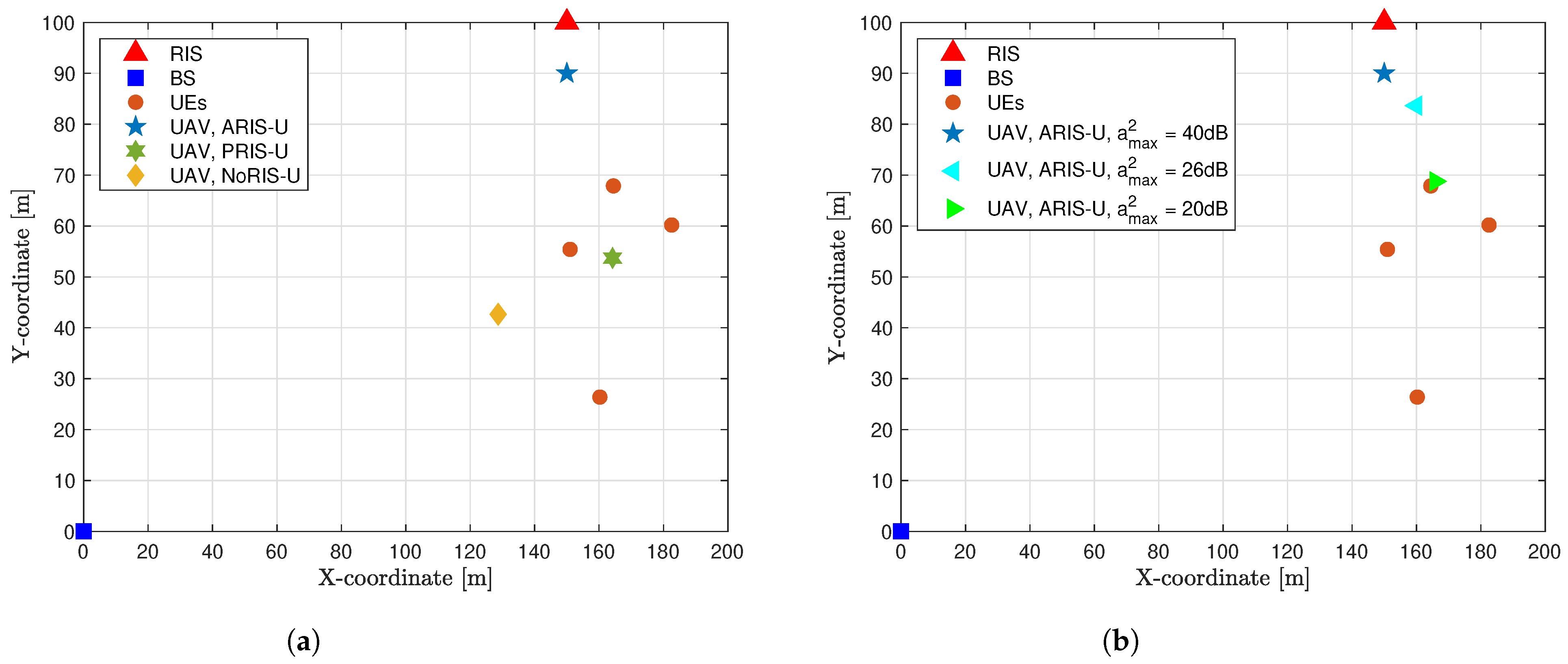
4.1. Simulation Setup

This section presents numerical results to evaluate the performance of the proposed algorithm. For the simulation, the UAV is assumed to operate at a fixed altitude of h u a v = 100 m. The simulation area spans 200 × 100 m2, with the BS located at r b = [0, 0, 0] m. We consider four UEs, K = 4, randomly and uniformly distributed within a circle of radius 50 m, centered at [150, 50, 0] m. The ARIS consists of N = 32 elements and is located at r i = [150, 100, 50] m. In the simulations, we set σ r 2 = ( η + 1 ) σ 2 , where σ r 2 denotes the total power of noise and residual self-interference from the ARIS, with η = 1 dB representing the estimated residual self-interference due to the active elements, as noted in [33,48]. The QoS requirement for all UEs is set to 1 Mbps. The primary simulation parameters are detailed in Table 2. Convex sub-problems were solved using YALMIP toolbox with the MOSEK solver in MATLAB R2024a on a desktop computer with 64 GB RAM and an Intel Core i7-9700 CPU running at 3.00 GHz. The convergence criterion was set to 10 3 . For robustness and reliability, each simulation result is averaged over 50 channel realizations.
To evaluate the effectiveness of our proposed algorithm, which jointly optimizes resource allocation, ARIS reflection coefficients, and UAV placement (referred to as “ARIS-U”), we compare its performance with the following four schemes:
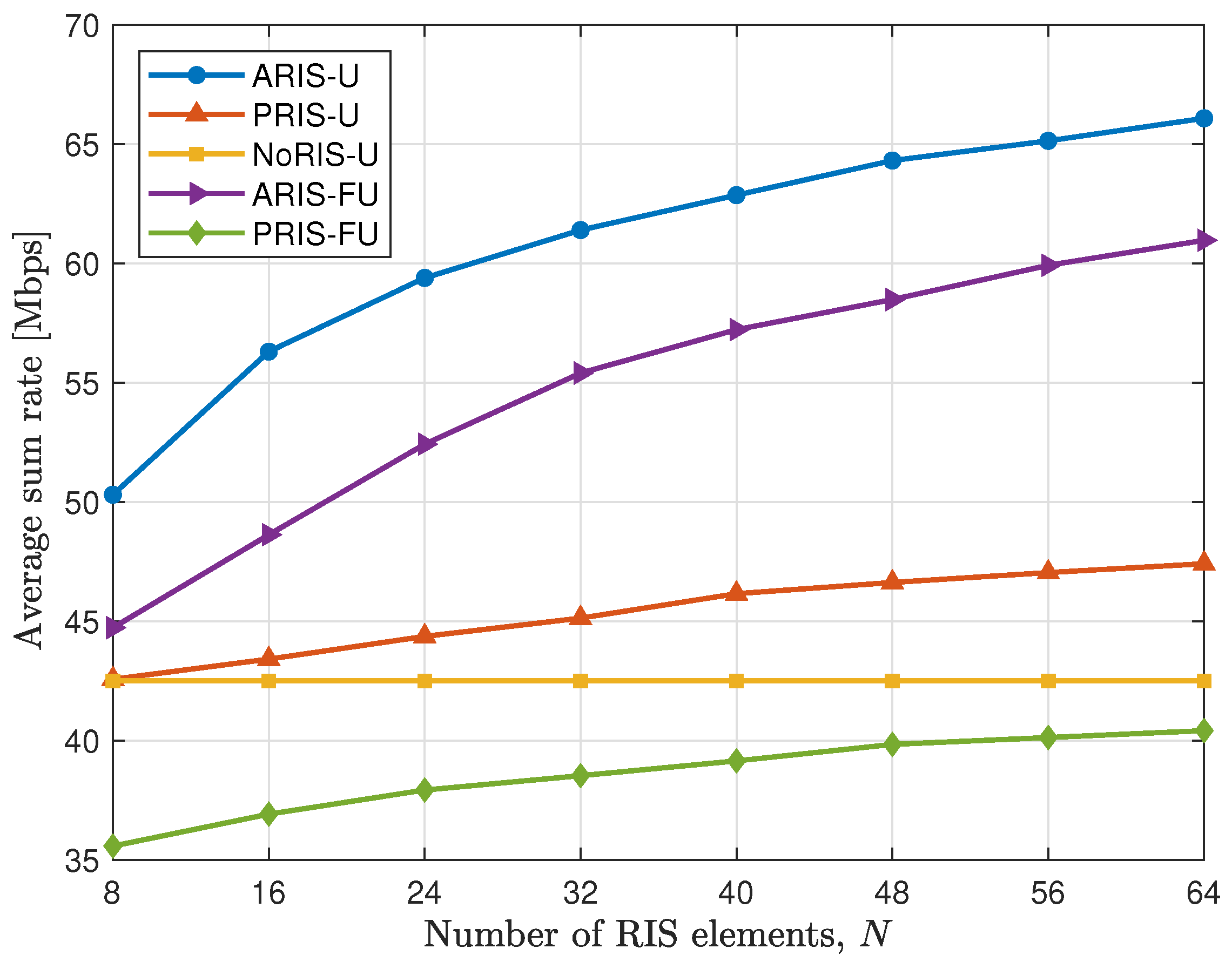
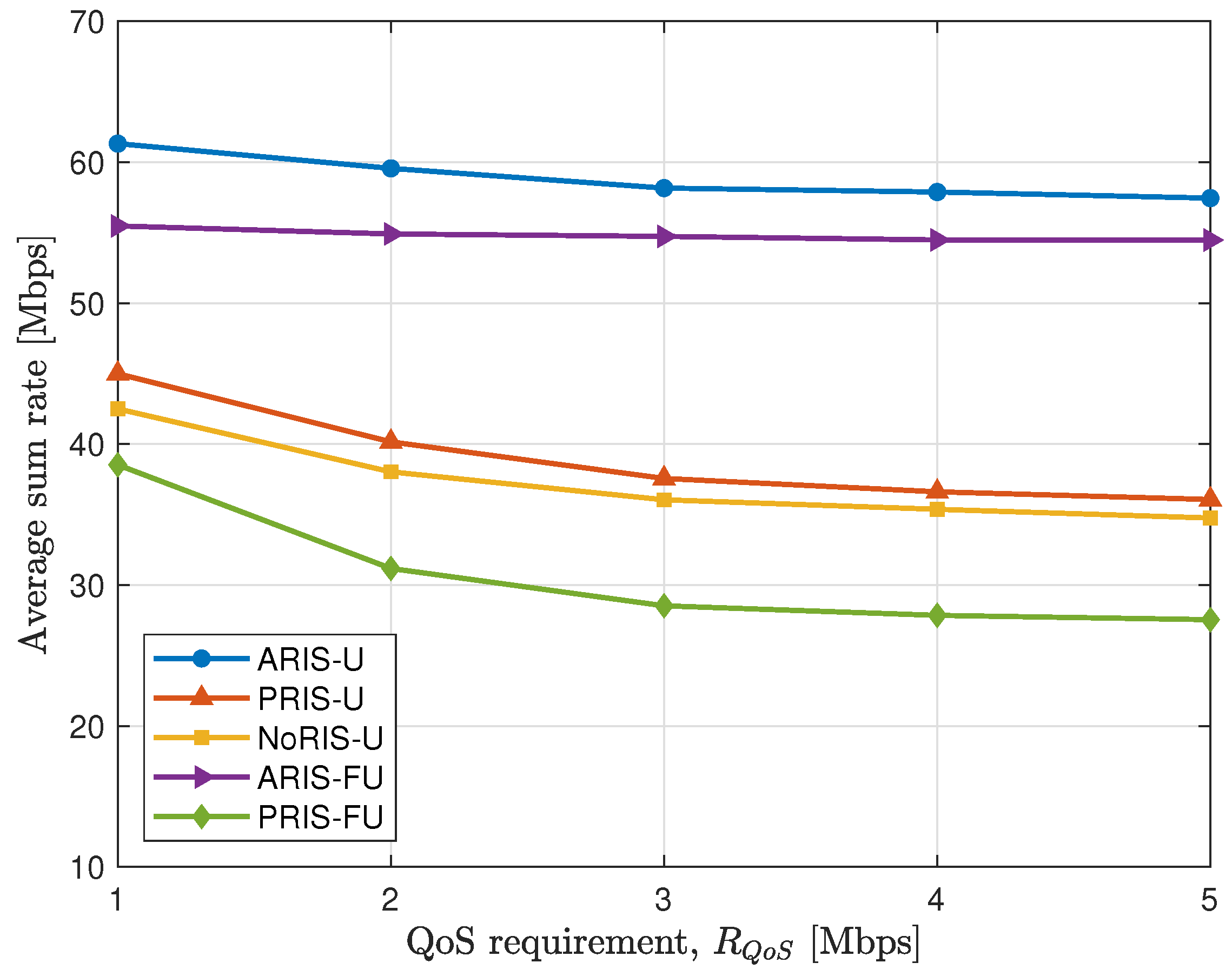
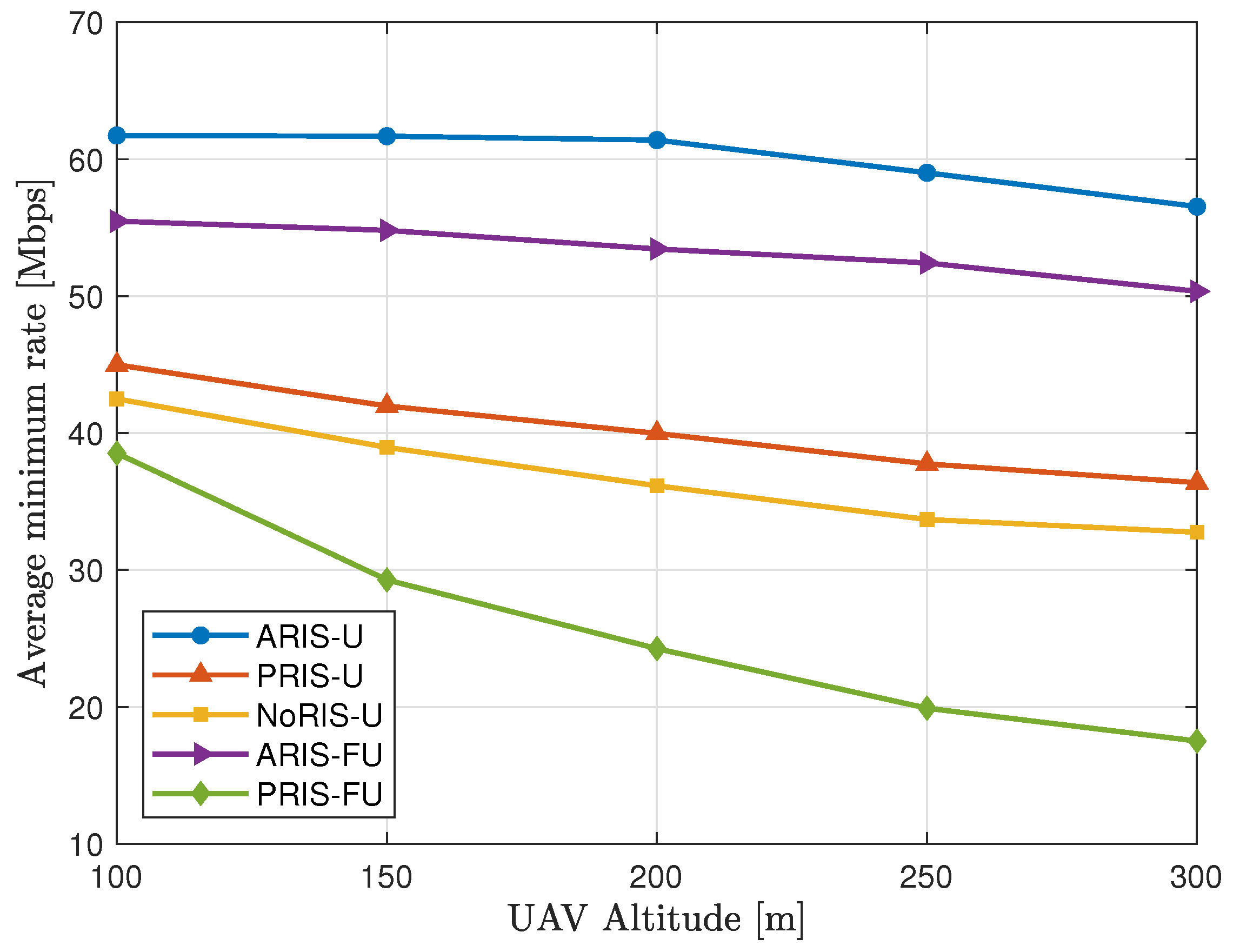
  • PRIS-U: In this scheme, all elements of the RIS are set to be passive. The resource allocation, PRIS reflection coefficients, and UAV placement are jointly optimized.
  • NoRIS-U: This framework optimizes resource allocation and UAV placement while omitting the RIS from the overall system.
  • ARIS-FU: In this scheme, only resource allocation and ARIS reflection coefficients are jointly optimized, while the UAV placement is kept fixed.
  • PRIS-FU: This scheme optimizes resource allocation and the RIS reflection coefficients, with the RIS configured as passive and the UAV placement fixed.

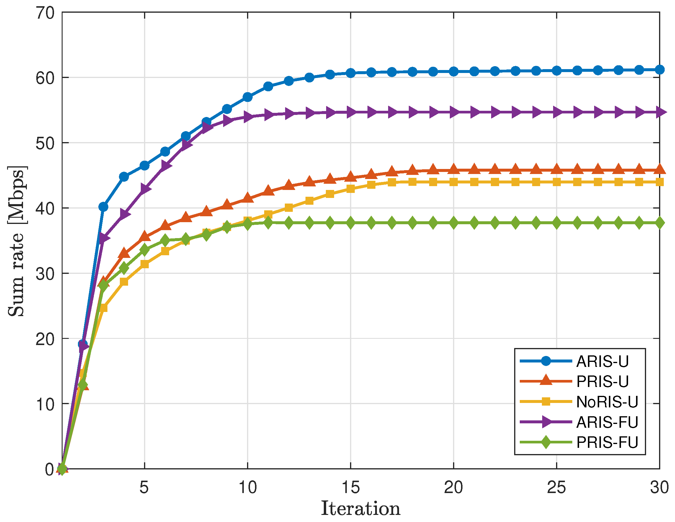
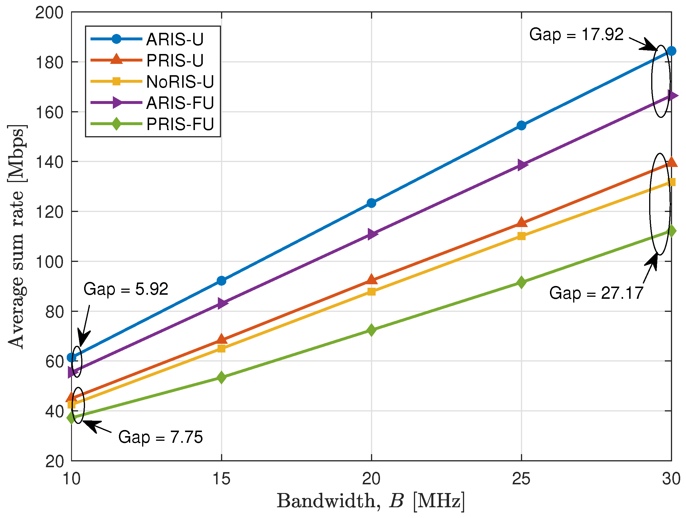
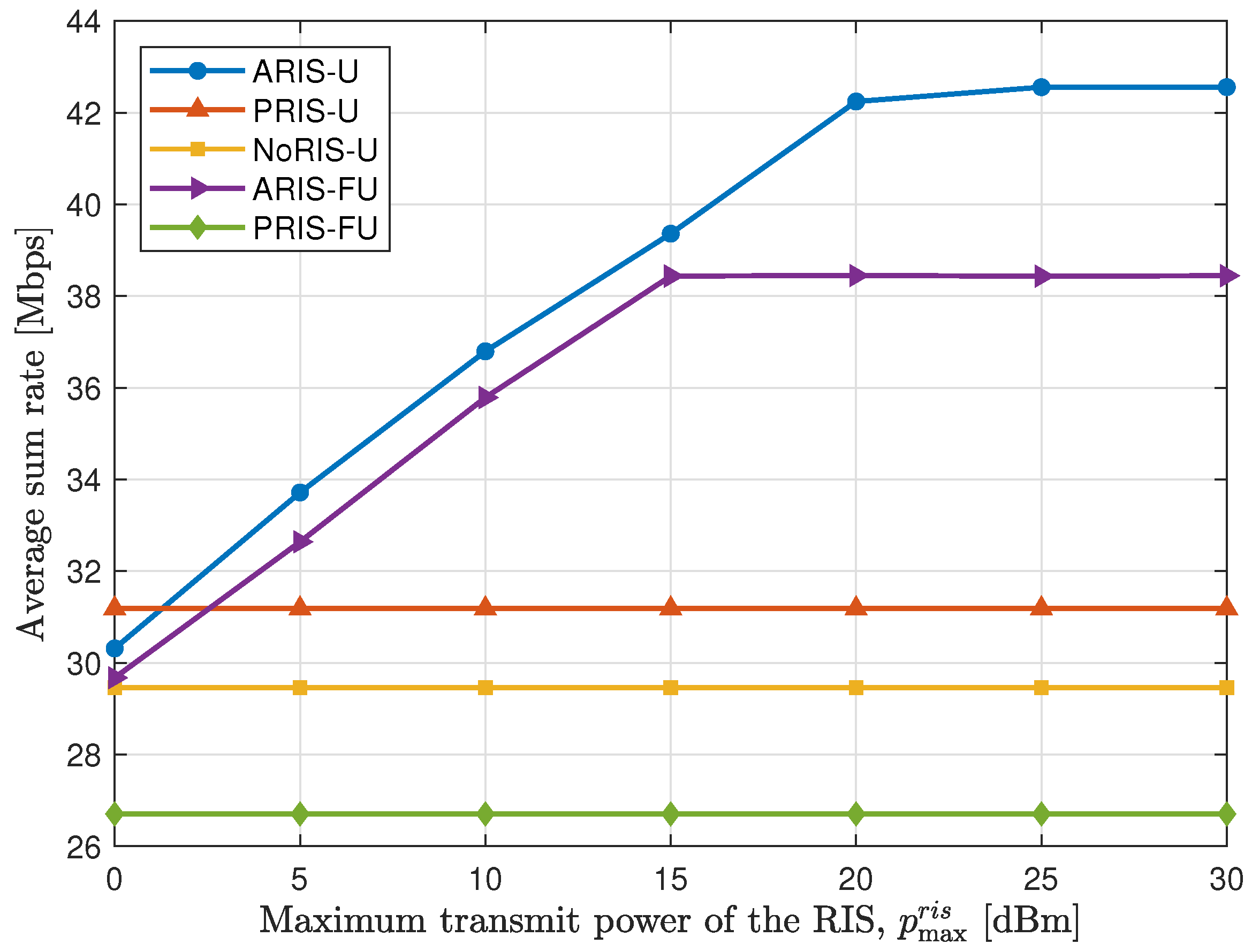
4.2. Simulation Results

Figure 2a illustrates the optimal placement of the UAV, as determined by the proposed alternating optimization algorithm across different schemes. We compare the optimal UAV placement for the following three scenarios: ARIS, PRIS, and without RIS. The parameters used for this comparison are P max u a v = 30 dBm, p max r i s = 20 dBm, and a max 2 = 40 dB. In the NoRIS-U scheme, the optimal UAV placement is positioned between the BS and UEs, remaining closer to the UEs. In the PRIS-U scheme, the optimal UAV placement hovers within the operational range of the UEs. However, with the assistance of ARIS, the optimal UAV placement shifts closer to the RIS. This indicates that ARIS significantly enhances channel performance, allowing the UAV to leverage strong signal paths from the RIS without needing to position itself near the UEs.
Moreover, as shown in Figure 2b, increasing the maximum reflection amplitude of the ARIS elements causes the optimal UAV placement to move closer to the RIS. For instance, when a max 2 = 20 dB, the optimal UAV placement remains near the UEs. However, as the maximum reflection amplitude increases to 26 dB or 40 dB, the optimal UAV placement gradually shifts closer to the RIS. This is because as the amplitude of the active elements increases, the incoming signal power at the RIS is amplified, resulting in stronger reflected signals. Consequently, the optimal UAV placement tends to move closer to the RIS to exploit these reflection channels, thereby boosting the signal power delivered to users and improving overall system performance.
Figure 3 presents the sum rate for all schemes as a function of the number of iterations, with K = 4, N = 32, and P max u a v = 30 dBm. The results show that the ARIS-U scheme achieves the highest sum rate among all schemes, demonstrating its superior performance. Notably, both the ARIS-FU and PRIS-FU schemes reach approximately 98% of their maximum sum rate within about 10 iterations. This rapid convergence is due to the fact that these frameworks focus solely on optimizing resource allocation and RIS reflection coefficients. In contrast, frameworks incorporating UAV placement optimization require more iterations to reach their maximum sum rate (about 16 iterations). However, this additional optimization substantially improves the overall sum rate, indicating that optimizing UAV placement significantly enhances system performance. Furthermore, the ARIS-assisted system consistently outperforms the PRIS across all scenarios, whether the UAV placements are fixed or optimized. These results highlight the effective synergy between the UAV’s mobility and the signal amplification provided by the ARIS.
Figure 4 illustrates the relationship between the average sum rate in DL communication and the maximum transmit power of the UAV, P max u a v . As expected, increasing P max u a v consistently boosts the average sum rate across all schemes. Specifically, the configurations without RIS and with PRIS show modest improvements in the average sum rate, while the ARIS provides significantly greater enhancements. For instance, the NoRIS-U and PRIS-U schemes yield gains of 15.24% and 20%, respectively, compared to the NoRIS-FU scheme. In contrast, ARIS-FU and ARIS-U schemes show remarkable increases in average sum rate, achieving gains of 44.16% and 57.1%, respectively. These results indicate that, compared to PRIS and configurations without RIS, ARIS effectively mitigates path loss and achieves substantial gains in the average sum rate.
Figure 5 depicts the impact of varying bandwidth on the average sum rate performance across all schemes. As shown in the figure, the average sum rate consistently increases with bandwidth for all schemes, with the ARIS-U scheme achieving the highest performance. Specifically, the ARIS-U scheme attains approximately 42.56 Mbps at 10 MHz and escalates to 127.78 Mbps at 30 MHz. The PRIS-U and NoRIS-U schemes also benefits from bandwidth expansion, achieving approximately 96.6 and 91.32 Mbps at 30 MHz, respectively, though they still lag behind the ARIS-U scheme. By optimizing the UAV’s placement, the sum rate gap between the ARIS-U and ARIS-FU schemes increases significantly, tripling as the bandwidth grows from 10 MHz to 30 MHz. Similarly, the gap between the PRIS-U and PRIS-FU schemes expands by a factor of 3.5 over the same bandwidth range.
Figure 6 illustrates the average sum rate of all schemes across varying values of p max r i s , with P max u a v = 30 dBm. As expected, the sum rate of the NoRIS-U, PRIS-U, and PRIS-FU schemes remains unchanged, as these configurations do not rely on the ARIS. Conversely, the ARIS-U and ARIS-FU schemes demonstrate noticeable improvements in the average sum rate as p max r i s increases, peaking at 20 dBm and 15 dBm, respectively. Beyond these peak values, further increases in p max r i s do not enhance the average sum rate due to saturation effects. This behavior is attributed to the hardware and power limitations of the ARIS elements, as dictated by constraints (11f)–(11g). Interestingly, at p max r i s = 0 dBm, the PRIS-U scheme outperforms the ARIS-U and ARIS-FU schemes. This occurs because low p max r i s values fail to provide sufficient power for distribution among all the ARIS elements, limiting their amplification capability. Consequently, the reflection amplitude ( | α | ) falls below 1, leading to signal attenuation rather than amplification in the ARIS configurations. As a result, the data rates achieved by PRIS schemes exceed those of ARIS schemes in such scenarios. This highlights a critical aspect of ARIS systems; the requirement for adequate power supply to effectively drive ARIS elements, while ARIS technology significantly enhances network performance, it is limited by hardware constraints and energy efficiency challenges. Practical deployment demands careful power allocation and resource management to optimize performance.
Figure 7 highlights the impact of the number of RIS elements on the average sum rate performance, demonstrating notable improvements for both passive and active RIS configurations. The ARIS configuration, however, clearly outperforms its passive counterpart. Specifically, as the number of RIS elements increases from 8 to 64, the average sum rate for the PRIS-FU and PRIS-U schemes rise from 24.66 Mbps to 28.01 Mbps (an increase of 3.35 Mbps) and from 29.5 Mbps to 32.86 Mbps (an increase of 3.36 Mbps), respectively. In contrast, the ARIS configuration achieves significantly greater enhancements. The average sum rate for the ARIS-U and ARIS-FU schemes escalates from 31 Mbps to 42.26 Mbps (an increase of 11.26 Mbps) and from 34.87 Mbps to 45.8 Mbps (an increase of 10.93 Mbps), respectively. These results emphasize that the performance improvement in ARIS-aided systems far exceeds that of PRIS-aided systems as the number of RIS elements increases. This demonstrates that the ARIS configuration significantly enhances communication performance, particularly when the number of RIS elements ranges from 8 to 64.
Figure 8 shows the impact of the QoS requirement ( R Q o S ) on the system’s average sum rate. Overall, the performance gains across all schemes decline as R Q o S increases. This trend occurs because higher QoS requirements compel the system to allocate more resources to meet minimum rate constraints, leaving fewer resources available to maximize the total rate, thereby reducing overall system performance. However, the ARIS-U and ARIS-RU schemes exhibit remarkable resilience even as R Q o S increases. For example, when R Q o S increases from 1 to 5 Mbps, the average sum rate for the ARIS-U scheme decreases by only 2.68 Mbps, while the ARIS-FU scheme experiences a minimal reduction of 0.69 Mbps. In contrast, the PRIS-U scheme undergoes a significant drop of 7.62 Mbps over the same range. These findings highlight the significant advantages of ARIS-aided systems, which can maintain high system performance even under stringent QoS constraints. This robustness makes ARIS an effective solution for scenarios with demanding QoS requirements.
In Figure 9, the system’s performance is evaluated across various UAV altitudes, ranging from 100 m to 300 m. It is evident from the figure that the average sum rate decreases for all schemes as the UAV altitude increases, primarily due to higher path loss and reduced signal strength. Among the schemes, the ARIS-U consistently achieves the highest average sum rate across all altitudes. In comparison, the PRIS-U and NoRIS-U schemes exhibit lower average sum rates, with PRIS-U outperforming NoRIS-U owing to the PRIS’s ability to enhance signal propagation. The PRIS-FU scheme shows significantly lower performance compared to the other schemes. Furthermore, the ARIS-U and ARIS-FU schemes experience a slower rate of decline, demonstrating the advantages of ARIS in improving signal strength and mitigating path loss. These results emphasize the effectiveness of ARIS in maintaining superior performance across varying UAV altitudes.

5. Conclusions

In this work, we introduced a novel communication architecture integrating UAV with ARIS in a wireless backhaul system to address critical challenges in next-generation wireless connectivity. Our approach effectively maximizes the achievable system sum rate by jointly optimizing UAV placement, transmit power, ARIS reflection coefficients, and resource allocation strategies, all while ensuring compliance with backhaul capacity constraints. To tackle the non-convexity of the optimization problem, we decomposed the problem into three sub-problems based on the BCA approach and applied IA techniques to address the non-convex constraints, developing a holistic AO framework to iteratively solve these sub-problems. Numerical evaluations validated the effectiveness of the proposed approach, achieving up to a 59% improvement in the average sum rate compared to conventional benchmark schemes, such as those using PRIS or fixed UAV placements. The results highlight the transformative potential of ARIS-assisted UAV systems in advancing next-generation communication networks by providing robust and scalable solutions. For future research, the integration of RIS-aided air-ground communication systems with multiple UAVs and multi-antenna devices presents a promising direction for further exploration and innovation. Additionally, we plan to incorporate UAV mobility models to evaluate the impact of UAV movement and dynamic trajectories on system performance. This will enable a deeper understanding of how mobility influences network stability, capacity, and overall efficiency, paving the way for more adaptive and effective communication strategies.

Author Contributions

Conceptualization, T.-T.-M.T., B.-M.V. and O.-S.S.; methodology, T.-T.-M.T., B.-M.V. and O.-S.S.; validation, T.-T.-M.T., B.-M.V. and O.-S.S.; investigation, T.-T.-M.T., B.-M.V. and O.-S.S.; writing—original draft preparation, T.-T.-M.T., B.-M.V. and O.-S.S.; writing—review and editing, T.-T.-M.T., B.-M.V. and O.-S.S.; visualization, O.-S.S.; supervision, O.-S.S.; project administration, O.-S.S.; funding acquisition, O.-S.S. All authors have read and agreed to the published version of the manuscript.

Funding

This work was supported by a National Research Foundation of Korea (NRF) grant funded by the Korean government (MSIT) under Grant RS-2023-00208995.

Institutional Review Board Statement

Not applicable.

Informed Consent Statement

Not applicable.

Data Availability Statement

The data presented in this study are available on request from the corresponding author.

Conflicts of Interest

The authors declare no conflicts of interest.

References

  1. Li, B.; Fei, Z.; Zhang, Y. UAV communications for 5G and beyond: Recent advances and future trends. IEEE Internet Things J. 2018, 6, 2241–2263. [Google Scholar] [CrossRef]
  2. Yan, C.; Fu, L.; Zhang, J.; Wang, J. A comprehensive survey on UAV communication channel modeling. IEEE Access 2019, 7, 107769–107792. [Google Scholar]
  3. Zeng, Y.; Wu, Q.; Zhang, R. Accessing from the sky: A tutorial on UAV communications for 5G and beyond. Proc. IEEE 2019, 107, 2327–2375. [Google Scholar] [CrossRef]
  4. Mohd Noor, N.; Abdullah, A.; Hashim, M. Remote sensing UAV/drones and its applications for urban areas: A review. IOP Conf. Ser. Earth Environ. Sci. 2018, 169, 012003. [Google Scholar] [CrossRef]
  5. Gong, S.; Lu, X.; Hoang, D.T.; Niyato, D.; Shu, L.; Kim, D.I.; Liang, Y.C. Toward smart wireless communications via intelligent reflecting surfaces: A contemporary survey. IEEE Commun. Surv. Tutor. 2020, 22, 2283–2314. [Google Scholar] [CrossRef]
  6. Vu, B.M.; Shin, O.S. Optimization of IRS-assisted OFDMA SWIPT systems with dynamic subcarrier allocation and AC computing. In Proceedings of the 14th International Conference on Information and Communication Technology Convergence (ICTC), Jeju Island, Republic of Korea, 11–13 October 2023; IEEE: Piscataway, NJ, USA, 2023; pp. 613–615. [Google Scholar]
  7. Dang, X.T.; Nguyen, H.V.; Shin, O.S. Physical layer security for IRS-UAV-assisted cell-free massive MIMO systems. IEEE Access 2024, 12, 89520–89537. [Google Scholar] [CrossRef]
  8. Zhang, Z.; Dai, L.; Chen, X.; Liu, C.; Yang, F.; Schober, R.; Poor, H.V. Active RIS vs. passive RIS: Which will prevail in 6G? IEEE Trans. Commun. 2022, 71, 1707–1725. [Google Scholar] [CrossRef]
  9. Ahmed, M.; Wahid, A.; Laique, S.S.; Khan, W.U.; Ihsan, A.; Xu, F.; Chatzinotas, S.; Han, Z. A survey on STAR-RIS: Use cases, recent advances, and future research challenges. IEEE Internet Things J. 2023, 10, 14689–14711. [Google Scholar] [CrossRef]
  10. Lyu, J.; Zhang, R. Hybrid active/passive wireless network aided by intelligent reflecting surface: System modeling and performance analysis. IEEE Trans. Wirel. Commun. 2021, 20, 7196–7212. [Google Scholar] [CrossRef]
  11. Ge, Y.; Fan, J.; Li, G.Y.; Wang, L.C. Intelligent reflecting surface-enhanced UAV communications: Advances, challenges, and prospects. IEEE Wirel. Commun. 2023, 30, 119–126. [Google Scholar] [CrossRef]
  12. Park, K.W.; Kim, H.M.; Shin, O.S. A survey on intelligent-reflecting-surface-assisted UAV communications. Energies 2022, 15, 5143. [Google Scholar] [CrossRef]
  13. Zeng, Y.; Xu, J.; Zhang, R. Energy minimization for wireless communication with rotary-wing UAV. IEEE Trans. Wirel. Commun. 2019, 18, 2329–2345. [Google Scholar] [CrossRef]
  14. Wu, Q.; Zhang, R. Common throughput maximization in UAV-enabled OFDMA systems with delay consideration. IEEE Trans. Commun. 2018, 66, 6614–6627. [Google Scholar] [CrossRef]
  15. Zeng, H.; Zhu, X.; Jiang, Y.; Wei, Z.; Sun, S.; Xiong, X. Toward UL-DL rate balancing: Joint resource allocation and hybrid-mode multiple access for UAV-BS-assisted communication systems. IEEE Trans. Commun. 2022, 70, 2757–2771. [Google Scholar] [CrossRef]
  16. Hua, M.; Yang, L.; Wu, Q.; Swindlehurst, A.L. 3D UAV trajectory and communication design for simultaneous uplink and downlink transmission. IEEE Trans. Commun. 2020, 68, 5908–5923. [Google Scholar] [CrossRef]
  17. Liu, Y.; Xie, J.; Xing, C.; Xie, S.; Luo, X. Self-organization of UAV networks for maximizing minimum throughput of ground users. IEEE Trans. Veh. Technol. 2024, 73, 11743–11755. [Google Scholar] [CrossRef]
  18. Nguyen, M.D.; Le, L.B.; Girard, A. Integrated UAV trajectory control and resource allocation for UAV-based wireless networks with co-channel interference management. IEEE Internet Things J. 2021, 9, 12754–12769. [Google Scholar] [CrossRef]
  19. Fu, S.; Feng, X.; Sultana, A.; Zhao, L. Joint power allocation and 3D deployment for UAV-BSs: A game theory based deep reinforcement learning approach. IEEE Trans. Wirel. Commun. 2023, 23, 736–748. [Google Scholar] [CrossRef]
  20. Nguyen, T.A.; Lee, J. Sparse code with minimum hamming distance of three for spin-torque transfer magnetic random access memory. IEEE Access 2023, 11, 114071–114079. [Google Scholar] [CrossRef]
  21. Panigrahi, C.R.; Sarkar, J.L.; Pati, B.; Buyya, R.; Mohapatra, P.; Majumder, A. Mobile cloud computing and wireless sensor networks: A review, integration architecture, and future directions. IET Netw. 2021, 10, 141–161. [Google Scholar] [CrossRef]
  22. Tipper, D.; Babay, A.; Palanisamy, B.; Krishnamurthy, P. Network connectivity resilience in next generation backhaul networks: Challenges and future opportunities. IEEE Trans. Netw. Serv. Manag. 2024, 21, 5321–5334. [Google Scholar] [CrossRef]
  23. Mohajer, A.; Sorouri, F.; Mirzaei, A.; Ziaeddini, A.; Rad, K.J.; Bavaghar, M. Energy-aware hierarchical resource management and backhaul traffic optimization in heterogeneous cellular networks. IEEE Syst. J. 2022, 16, 5188–5199. [Google Scholar] [CrossRef]
  24. Huang, Y.; Cui, M.; Zhang, G.; Chen, W. Bandwidth, power, and trajectory optimization for UAV base station networks with backhaul and user QoS constraints. IEEE Access 2020, 8, 67625–67634. [Google Scholar] [CrossRef]
  25. Youssef, M.J.; Farah, J.; Nour, C.A.; Douillard, C. Full-duplex and backhaul-constrained UAV-enabled networks using NOMA. IEEE Trans. Veh. Technol. 2020, 69, 9667–9681. [Google Scholar] [CrossRef]
  26. Diaz-Vilor, C.; Lozano, A.; Jafarkhani, H. Cell-free UAV networks with wireless fronthaul: Analysis and optimization. IEEE Trans. Wirel. Commun. 2023, 23, 2054–2069. [Google Scholar] [CrossRef]
  27. Tafintsev, N.; Moltchanov, D.; Chiumento, A.; Valkama, M.; Andreev, S. Airborne integrated access and backhaul systems: Learning-aided modeling and optimization. IEEE Trans. Veh. Technol. 2023, 72, 16553–16566. [Google Scholar] [CrossRef]
  28. Youssef, M.J.; Nour, C.A.; Farah, J.; Douillard, C. Backhaul-constrained resource allocation and 3D placement for UAV-enabled networks. In Proceedings of the IEEE 90th Vehicular Technology Conference (VTC2019-Fall), Honolulu, HI, USA, 22–25 September 2019; IEEE: Piscataway, NJ, USA, 2019; pp. 1–7. [Google Scholar]
  29. Yin, S.; Li, L.; Yu, F.R. Resource allocation and basestation placement in downlink cellular networks assisted by multiple wireless powered UAVs. IEEE Trans. Veh. Technol. 2019, 69, 2171–2184. [Google Scholar] [CrossRef]
  30. Wei, Z.; Cai, Y.; Sun, Z.; Ng, D.W.K.; Yuan, J.; Zhou, M.; Sun, L. Sum-rate maximization for IRS-assisted UAV OFDMA communication systems. IEEE Trans. Wirel. Commun. 2020, 20, 2530–2550. [Google Scholar] [CrossRef]
  31. Xie, W.; Li, Y.; Yu, C.; Wang, J.; Peng, X.; Zhu, P. Sum rate maximization for self-sustainable IRS-assisted UAV communications. IEEE Commun. Lett. 2022, 27, 640–644. [Google Scholar] [CrossRef]
  32. Peng, Z.; Liu, R.; Pan, C.; Zhang, Z.; Wang, J. Energy minimization for active RIS-aided UAV-enabled SWIPT systems. IEEE Commun. Lett. 2024, 28, 1372–1376. [Google Scholar] [CrossRef]
  33. Nguyen, N.T.; Nguyen, V.D.; Van Nguyen, H.; Wu, Q.; Tölli, A.; Chatzinotas, S.; Juntti, M. Fairness enhancement of UAV systems with hybrid active-passive RIS. IEEE Trans. Wirel. Commun. 2023, 23, 4379–4396. [Google Scholar] [CrossRef]
  34. Diamanti, M.; Charatsaris, P.; Tsiropoulou, E.E.; Papavassiliou, S. The prospect of reconfigurable intelligent surfaces in integrated access and backhaul networks. IEEE Trans. Green Commun. Netw. 2021, 6, 859–872. [Google Scholar] [CrossRef]
  35. Nguyen, M.D.; Le, L.B.; Girard, A. UAV placement and resource allocation for intelligent reflecting surface assisted UAV-based wireless networks. IEEE Commun. Lett. 2022, 26, 1106–1110. [Google Scholar] [CrossRef]
  36. Vu, B.M.; Dang, T.N.; Shin, O.S. Rate fairness optimization for mixed FSO/RF IRS-assisted UAV communication systems. In Proceedings of the 2023 RIVF International Conference on Computing and Communication Technologies (RIVF), Hanoi, Vietnam, 23–25 December 2023; IEEE: Piscataway, NJ, USA, 2023; pp. 200–205. [Google Scholar]
  37. Nguyen, T.T.; Pham, Q.V.; Nguyen, V.D.; Lee, J.H.; Kim, Y.H. Resource allocation for energy efficiency in OFDMA-enabled WPCN. IEEE Wirel. Commun. Lett. 2020, 9, 2049–2053. [Google Scholar] [CrossRef]
  38. Yang, F.; Xu, W.; Zhang, Z.; Guo, L.; Lin, J. Energy efficiency maximization for relay-assisted WPCN: Joint time duration and power allocation. IEEE Access 2018, 6, 78297–78307. [Google Scholar] [CrossRef]
  39. Huang, D.; Cui, M.; Zhang, G.; Chu, X.; Lin, F. Trajectory optimization and resource allocation for UAV base stations under in-band backhaul constraint. EURASIP J. Wirel. Commun. Netw. 2020, 2020, 83. [Google Scholar] [CrossRef]
  40. Li, J.; Xu, S.; Liu, J.; Cao, Y.; Gao, W. Reconfigurable intelligent surface enhanced secure aerial-ground communication. IEEE Trans. Commun. 2021, 69, 6185–6197. [Google Scholar] [CrossRef]
  41. Peng, Q.; Wu, Q.; Chen, G.; Liu, R.; Ma, S.; Chen, W. Hybrid active-passive IRS assisted energy-efficient wireless communication. IEEE Commun. Lett. 2023, 27, 2202–2206. [Google Scholar] [CrossRef]
  42. Khoshafa, M.H.; Ngatched, T.M.; Ahmed, M.H.; Ndjiongue, A.R. Active reconfigurable intelligent surfaces-aided wireless communication system. IEEE Commun. Lett. 2021, 25, 3699–3703. [Google Scholar] [CrossRef]
  43. Nguyen, K.G.; Vu, Q.D.; Tran, L.N.; Juntti, M. Energy efficiency fairness for multi-pair wireless-powered relaying systems. IEEE J. Sel. Areas Commun. 2018, 37, 357–373. [Google Scholar] [CrossRef]
  44. Nguyen, T.V.; Nguyen, V.D.; da Costa, D.B.; An, B. Hybrid user pairing for spectral and energy efficiencies in multiuser MISO-NOMA networks with SWIPT. IEEE Trans. Commun. 2020, 68, 4874–4890. [Google Scholar] [CrossRef]
  45. Marks, B.R.; Wright, G.P. A general inner approximation algorithm for nonconvex mathematical programs. Oper. Res. 1978, 26, 681–683. [Google Scholar] [CrossRef]
  46. Do, T.N.; Nguyen, V.D.; Shin, O.S.; An, B. Simultaneous uplink and downlink transmissions for wireless powered communication networks. IEEE Commun. Lett. 2018, 23, 374–377. [Google Scholar] [CrossRef]
  47. Dang, X.T.; Shin, O.S. Optimization of energy efficiency for federated learning over unmanned aerial vehicle communication networks. Electronics 2024, 13, 1827. [Google Scholar] [CrossRef]
  48. Nguyen, N.T.; Vu, Q.D.; Lee, K.; Juntti, M. Hybrid relay-reflecting intelligent surface-assisted wireless communications. IEEE Trans. Veh. Technol. 2022, 71, 6228–6244. [Google Scholar] [CrossRef]
  49. Nguyen-Kha, H.; Nguyen, H.V.; Le, M.T.; Shin, O.S. Joint UAV placement and IRS phase shift optimization in downlink networks. IEEE Access 2022, 10, 111221–111231. [Google Scholar] [CrossRef]
  50. Nguyen, M.D.; Ho, T.M.; Le, L.B.; Girard, A. UAV placement and bandwidth allocation for UAV based wireless networks. In Proceedings of the 2019 IEEE Global Communications Conference (GLOBECOM), Waikoloa, HI, USA, 9–13 December 2019; IEEE: Piscataway, NJ, USA, 2019; pp. 1–6. [Google Scholar]
Figure 1. A schematic of an ARIS-assisted UAV communication network with wireless backhaul.
Drones 09 00111 g001
Figure 2. (a) Optimal UAV location in different schemes. (b) Impact of maximum reflection amplitude of ARIS on optimal UAV location.
Drones 09 00111 g002
Figure 3. Convergence behavior of the sum rate performance.
Drones 09 00111 g003
Figure 4. The average sum rate as a function of the UAV’s power budget.
Drones 09 00111 g004
Figure 5. The average sum rate as a function of the system bandwidth.
Drones 09 00111 g005
Figure 6. The average sum rate as a function of p max r i s .
Drones 09 00111 g006
Figure 7. The average sum rate as a function of the number of RIS elements.
Drones 09 00111 g007
Figure 8. The average sum rate as a function of R Q o S .
Drones 09 00111 g008
Figure 9. The average sum rate as a function of UAV altitude.
Drones 09 00111 g009
Table 1. Computational complexity analysis of the proposed algorithm.
Sub-Problem p j q j Complexity
(29) 7 K + 1 7 K + 5 p 1 2 q 1 2.5 + q 1 3.5
(42) 4 K + N 2 6 K + N + 2 p 2 2 q 2 2.5 + q 2 3.5
(56) 5 K + 5 7 K + 6 p 3 2 q 3 2.5 + q 3 3.5
Total Complexity C = O ( I j = 1 3 ( p j 2 q j 2.5 + q j 3.5 ) )
Table 2. Simulation parameters for ARIS-assisted UAV communication with wireless backhaul.
ParameterDescriptionValue
r b s BS location[0, 0, 0] m
r i RIS location[50, 100, 50] m
h u a v UAV altitude100 m [33]
ρ 0 Path loss−30 dB [33,49]
α 0 , α 1 , α 2 Path loss exponents3.2, 2.0, 2.2 [33]
κ Rician factor10 [33,49]
BSystem bandwidth10 MHz [50]
P max u a v UAV power budget1 W [50]
P B BS power budget36 dBm [50]
σ 2 AWGN Noise−90 dBm [33,49]
p max r i s The power budget of RIS20 dBm [42]
a max 2 The maximum gain achievable by an active load20 dB [42]
Disclaimer/Publisher’s Note: The statements, opinions and data contained in all publications are solely those of the individual author(s) and contributor(s) and not of MDPI and/or the editor(s). MDPI and/or the editor(s) disclaim responsibility for any injury to people or property resulting from any ideas, methods, instructions or products referred to in the content.

