Article

Uncertainty Control Method for Non-Uniform Wear of the Driving Mechanism of Flapping Wing Aircraft

1
School of Sciences, Chang’an University, Xi’an 710064, China
2
School of Aeronautics, Northwestern Polytechnical University, Xi’an 710012, China
3
National Key Laboratory of Aircraft Configuration Design, Xi’an 710012, China
*
Authors to whom correspondence should be addressed.
These authors contributed equally to this work.
Drones 2025, 9(4), 282; https://doi.org/10.3390/drones9040282
Submission received: 24 February 2025 / Revised: 28 March 2025 / Accepted: 1 April 2025 / Published: 8 April 2025

Abstract

:
Flapping wing aircrafts have demonstrated unique advantages in military and civil fields due to their bio-inspired flight mechanisms. However, non-uniform wear in driving mechanisms remains a critical reliability concern during prolonged operation. This study presents a stochastic wear prediction framework that systematically integrates joint clearance dynamics, contact force variations, and material interaction parameters. Through accelerated life testing with flight condition simulations, the method establishes quantitative correlations between multi-source variables and wear progression patterns. Experimental validation confirms the framework’s effectiveness in predicting asymmetric wear distribution, with comparative analysis showing significant improvements in prediction accuracy over conventional single-factor models. The results identify three dominant wear contributors: dynamic clearance fluctuations, impact force randomness, and material compatibility limitations. These findings directly support the development of adaptive lubrication systems and wear-resistant material selection guidelines, offering practical solutions for enhancing flapping wing aircrafts’ reliability in complex operational scenarios.

1. Introduction

Flapping-wing aircraft are characterized by their small size, low noise, high flexibility, and stealth capabilities, making them suitable for reconnaissance and search-and-rescue operations [1]. As a new type of drone, they are particularly suited for missions requiring stealth and maneuverability, such as surveillance, reconnaissance, and search-and-rescue operations. The driving mechanism of the flapping wing aircraft is one of the key components affecting its flight performance. This mechanism converts electrical energy into mechanical energy needed for the up-and-down flapping motion, enabling the aircraft to achieve stable and efficient flight. However, during operation, the driving mechanism develops non-uniform joint wear patterns—a critical reliability issue distinct from uniform wear progression. Unlike uniform wear that causes predictable gradual degradation across contact surfaces, this localized wear creates three compounding effects: asymmetric stress concentrations at wear hotspots that accelerate material fatigue, dynamic instability from mismatched contact force distributions, and unpredictable clearance growth patterns that conventional linear models cannot capture. These characteristics make non-uniform wear particularly detrimental as it simultaneously reduces structural integrity while increasing vibration anomalies and maintenance unpredictability. This degradation not only affects the overall functionality of the mechanism but also poses a potential threat to the safety and reliability of the drone’s operations. Given the critical role of drones in both military and civilian applications, it is essential to research and understand the wear characteristics of flapping wing driving mechanisms with clearance joints. By calculating the wear reliability of these mechanisms, we can enhance the durability and performance of flapping wing aircrafts as drones, ensuring their continued effectiveness in diverse operational environments.
Domestic and foreign researchers in the study of the influence of clearance joints in dynamic mechanisms have focused on improving model accuracy and computational efficiency. Flores et al. [2] and López-Lombardero et al. [3,4] explored the clearance joint model and its impact on dynamic behavior through different methods. Li et al. [5] and Lin et al. [6] experimentally verified the nonlinear dynamic model based on Lagrange’s equation and introduced the motion accuracy reliability model. Wei et al. [7] and Zhu et al. [8] analyzed the influence of clearance on dynamic response based on Kane’s equation and the clearance collision theory, and established a flexible joint model. Roupa et al. [9] studied the kinematics and dynamics of planar multi-body systems. Zhuang [10] and Wang et al. [11] focused on clearance wear prediction and verification of the solar panel dynamic model. Zhou et al. [12] proposed a dynamic model of cable-driven manipulators considering friction and deformation. These studies emphasized the necessity of considering clearance and flexibility in dynamic models and demonstrated the application potential of multi-body dynamics in simulating mechanism behavior, wear, and fatigue damage, providing a scientific basis for design and optimization. However, there are still two key gaps that remain unsolved for flapping wing aircrafts applications. One is that existing clearance models mainly consider static/deterministic wear patterns and ignore multi-source random variables (e.g., material heterogeneity, impact angle variation) that are ubiquitous in flapping flight mechanisms. Another is the lack of integration of current reliability frameworks with real-time wear prediction, limiting their utility in adaptive maintenance planning.
In the study of the influence of clearance joints, the Archard wear model holds an important position due to its accuracy and applicability. This model correlates the wear depth with factors such as sliding speed, normal force, and hardness, and is consistent with experimental results. Wang et al. [13] applied the Archard model to railway wear analysis by optimizing SVR, improving the prediction accuracy. Jia et al. [14] utilized the Archard model to analyze the wear of flapping-wing unmanned aerial vehicles, revealing the relationship between wear volume and sliding speed, load, and hardness. Sun et al. [15] studied the wear of small-module gears based on the Archard model and the small-displacement torsion theory. Zhuang et al. [16] proposed a wear prediction method considering contact pressure and profile smoothness. Li et al. [17] studied the wear characteristics of solar cell array systems. Jiang et al. [18] analyzed the influence of wear on the dynamic response of multi-link mechanisms. Li et al. [19] and Jiang et al. [20] calculated the wear of aircraft landing gears based on the Archard model and proposed a reliability analysis method. The selection of Archard’s wear model for this study stems from its unique suitability for dynamic systems with multi-source stochastic variables. Compared to energy-based models like Fleischer’s approach that require precise micro-scale friction characterization, Archard’s wear model provides macroscopic wear prediction through measurable parameters making it particularly advantageous for UAV mechanisms where real-time material state monitoring is impractical. Compared to finite element analysis (FEA) methods that demand detailed stress–strain characterization and iterative material removal simulations, the Archard model offers superior computational efficiency for long-term wear evolution prediction in complex mechanisms. While statistical models like neural networks require extensive experimental datasets for training, Archard’s physics-based formulation ensures reliable extrapolation capability under varying working conditions.
In addition to the combination of the Archard model with machine learning, the Kriging method has also been combined with machine learning techniques in recent years, playing a significant role in reliability engineering [21]. Wang et al. [22] proposed a time-varying conditional reliability method based on the active learning Kriging model and Monte Carlo Simulation, further enhancing the computational efficiency. Wang et al. [23] proposed an adaptive Kriging-based probabilistic subset simulation (SS) method for small failure probability problems, which maintained the accuracy of estimation and improved the computational efficiency. Prentzas et al. [24] introduced a method of quantifying active learning Kriging basis (qAK) based on the updated probability density function (PDF), improving the reliability and robustness in structural reliability assessment. Zhao et al. [24] proposed a reliability assessment method based on the improved active learning Kriging method (AK-IS), demonstrating high efficiency and good robustness. Shi et al. [25] proposed a new learning function FNEIF based on Kriging for surrogate model construction to efficiently estimate the failure probability. Ouyang et al. [26] proposed an active learning reliability method based on Bootstrap Kriging (BAK-MCS), reducing the calls of the true limit state function and improving the modeling efficiency. Zhang et al. [27] proposed a new reliability analysis method based on the adaptive Kriging model and the improved Metropolis-Hastings importance sampling (iMHIS) algorithm, which is particularly suitable for small probability failure events involving multiple input random variables. Yuan et al. [28] proposed a new Bayesian framework integrating the active learning Kriging method to improve the prediction performance and reduce uncertainty. Gong et al. [29] proposed a Kriging surrogate model based on basis-adaptive polynomial chaos. In conclusion, the combination of the Kriging method with machine learning techniques has shown significant improvements in computational efficiency and prediction accuracy in structural reliability analysis. Through techniques, such as adaptive Kriging strategies, stratified importance sampling, probabilistic subset simulation, and new learning functions based on Kriging, researchers can effectively handle small failure probability problems and significantly improve the computational and modeling efficiency of structural reliability analysis while maintaining or improving the prediction accuracy. These studies not only promote the development of the Kriging method but also provide new perspectives and tools for the field of structural reliability analysis.
Furthermore, many studies have focused on the influence of clearance types on the dynamic performance of mechanical systems and sought optimization strategies to enhance the stability and efficiency of the systems. Zhang et al. [30] adopted a hybrid nonlinear continuous contact force model to study the dynamic behavior of the vehicle scissor door mechanism and found that the influence of the articulated joint clearance on vibration was greater than that of the planar higher pair clearance. Ding et al. [31] proposed a new normal contact force model based on the standard linear solid (SLS) model, considering energy dissipation and showing a good fit with the experimental data. Dong et al. [32] adopted the 6σ (DFSS) optimization strategy to improve the robustness and reliability of the navigation performance of unmanned surface vessels (USV), especially in the presence of uncertain factors. Dong et al. [33] established a flexible-rigid toggle-linkage system model considering mixed clearances and lubrication, confirming the necessity of clearances and flexibility to improve the simulation accuracy. Chen et al. [34] established a vector model of the lubrication clearance and an oil film bearing capacity model, and developed a dynamic model of the rigid-flexible coupling mechanism with lubrication clearances. Chen et al. [35] studied the dynamic behavior of a new planar nine-bar mechanism, considering the influences of dry friction clearances and lubrication clearances simultaneously. These studies not only enhance the understanding of the dynamic behavior of multi-body systems with clearances but also provide scientific guidance for the design and optimization of mechanical systems, emphasizing the importance of considering clearances and lubrication in the analysis of mechanical systems.
For the wear analysis of rotary joints with clearance, researchers mainly conduct simulation experiments through dynamic simulation software and usually assume uniform joint clearance to simplify the modeling. However, in reality, rotary joints often have non-uniform wear due to different structural motion principles. Zhuang et al. [36] developed a prediction method for the size of joint clearance based on ANFIS, obtained real-time wear data by monitoring the motion output, and proposed a wear prediction framework based on the multi-body dynamics theory. Zhang et al. [37] proposed a three-dimensional rotational clearance joint wear model considering the time-varying contact stiffness. This model combines modeling, contact force calculation, and wear depth calculation, providing an effective method for the wear prediction of three-dimensional rotational clearance joints. Wang et al. [38] analyzed the irregular wear effect of multiple clearances in planar multi-body mechanical systems. Taking the four-bar mechanism as the object, a non-uniform wear depth prediction model was established based on the Archard equation, and the influence of different factors on wear was studied. For the 3RSR parallel mechanism, Hou et al. [39] considered the spherical joint clearance, and a dynamic model was established based on the modified Flores contact force model and the Coulomb friction model, and the wear parameters were calculated based on the Archard wear model to analyze the influence of wear and clearance on the dynamic response. Li et al. [40] proposed a brand-new method to predict the wear of planar mechanical systems with multiple clearance joints, studied the interaction of clearance, driving conditions and wear, and integrated the contact force and friction effect into the Archard wear model to calculate the wear depth. These models comprehensively consider contact force, friction, clearance change and other factors, verify their accuracy through experiments, and quantify the wear depth based on the Archard wear model.
In the current research, the flapping-wing mechanism has unique motion characteristics, such as its complex motion patterns and multi-degree-of-freedom joint designs. These characteristics enable it to have excellent performance in dynamic and complex mechanical systems. However, these characteristics also lead to the non-uniform wear phenomenon easily occurring during the motion of the flapping-wing mechanism. Non-uniform wear refers to the situation in a mechanical system where, due to factors such as uneven load distribution and changes in contact stress, the wear rate of certain parts is significantly higher than that of other parts. In the flapping-wing mechanism, this wear phenomenon is particularly obvious because the loads and stress distributions that its joint parts bear during motion are very complex.
At present, the accurate prediction of non-uniform wear in flapping wing mechanisms remains an urgent problem to be solved. In mechanical systems, there are various uncertainty factors, such as manufacturing tolerances, material loss, and mechanism degradation. How these factors affect the wear and reliability of the system has not been fully studied. In addition, the existing wear prediction models may not accurately reflect the complex wear behavior in actual mechanical systems, especially under the influence of multi-source random variables. Moreover, there is currently a lack of an effective method to evaluate the wear reliability of mechanical systems considering non-uniform wear and uncertainty factors.
It is worth noting that our research team previously established, through systematic experimentation and theoretical modeling, a fundamental correlation framework and associated technical foundations linking the dynamic behavior of flapping-wing mechanisms to their wear evolution [41]. This work provides critical support for elucidating the dynamic contact mechanisms of clearance joints and the quantitative characterization of localized wear. Building upon this foundation, the current study conducts optimized and in-depth investigations.
Therefore, this paper conducts an in-depth study of the above problems and innovatively proposes the following solutions. Regarding the non-uniform wear prediction method, we present a joint non-uniform wear prediction method considering multi-source random variables. Taking the driving mechanism of flapping-wing unmanned aerial vehicles as the research object, the effectiveness of the method is verified by comparing with the actual experimental joint wear results. For uncertainty considerations, we study the wear reliability and sensitivity of the flapping-wing driving mechanism considering uncertainties, which provides guidance for the life prediction and optimal design of mechanical systems. This paper combines the Newton-Euler method, the L-N contact force model, and the improved Coulomb friction model, combines dynamic modeling with wear analysis, establishes a multi-body dynamic model including clearance joints, and obtains the non-uniform wear characteristics using the Archard wear model. Based on the consideration of non-uniform wear, we establish a wear reliability model and calculate the wear reliability of the driving mechanism using the AK-MCS method. It provides new theoretical support and practical guidance for the design and maintenance of the driving mechanism of flapping-wing unmanned aerial vehicles.
The main contents of the following parts of this paper are as follows. Section 2 establishes a multi-body dynamics model of the flapping-wing driving mechanism including clearance joints; Section 3 analyzes the wear characteristics of the clearance joints of the flapping-wing driving mechanism based on the Archard wear model; Section 4 analyzes and quantifies the uncertainty factors such as manufacturing tolerances and material property variations in the flapping-wing driving mechanism; Section 5 establishes a wear reliability model of the flapping-wing driving mechanism considering uncertainties, and calculates its wear reliability using the AK-MCS method; and Section 6 verifies the consistency between the predicted non-uniform wear characteristics of the model and the actual results through dynamic simulation and actual experiments, and conducts reliability and sensitivity analysis. Finally, the main findings of this study are summarized in Section 7. The main process of this study is shown in Figure 1.

2. Multibody Dynamics Analysis of Joint with Clearance

2.1. Kinematics Equations for Ideal Joint Multibody System

A multibody system is a collection of several components connected by different joints that constrain their relative motions by applying forces and moments. In this study, the Newton-Euler equation is utilized to solve the problem of a constrained multi-body system, while a set of differential and algebraic equations are developed in conjunction with the Baumgarte stability method [20,21] in order to reduce the numerical stability problem. The equations are as follows.
For ideal joints without clearance, the m holonomic constraints Φ enforcing geometric compatibility between n components’ Cartesian coordinates are derived from joint kinematics [19]:
Φ ( q , t ) = 0
where q is the position coordinate vector of components, and t is the time of operation of the mechanism.
Equation (1) obtains the velocity constraint formula (Equation (2)) by the first order differentiation of time, and the acceleration constraint formula (Equation (3)) by the second order differentiation of time:
Φ q q ˙ = Φ t
Φ q q ¨ = ( Φ q q ˙ ) q q ˙ 2 Φ q t q ˙ Φ t t
where Φ q is the Jacobi matrix of the constraint equation, Φ t is the partial derivative of Φ with respect to time t , q ˙ is the velocity vectors of the component, and q ¨ is the acceleration vectors of the component.
The equation of motion of a constrained multibody system can be written:
M q ¨ + Φ q T λ = g
where M is the mass matrix, λ is the Lagrange multiplier vector, and g is the generalized force matrix.
Combining Equations (3) and (4), we obtain [10]:
( M Φ q T Φ q 0 ) ( q ¨ λ ) = ( g γ )
In order to control and stabilize the deviation, Equation (5) is solved with the Baumgarte stabilization method. The Baumgarte stabilization algorithm allows for smaller constraint violations before correcting the algorithm. The Baumgarte stabilization algorithm replaces the differential equations in Equation (6):
( M Φ q T Φ q 0 ) ( q ¨ λ ) = ( g + F c γ 2 α Φ ˙ β 2 Φ )
Generally, positive constants for α and β ensure the stability of Equation (6), and when α and β take equal values, larger damping is obtained, which can quickly stabilize the response of the system.

2.2. Vector Modeling of Clearance for Revolving Joint

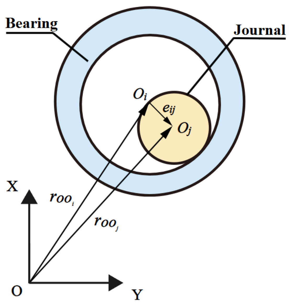
In order to describe the clearance between the joint reasonably, this study adopts the clearance vector model as shown in Figure 2. The clearance vector model is introduced in the revolving joint containing a clearance vector.
It is assumed that the revolving joint consists of the bearing and the journal, and the starting point of the clearance vector is the center of the bearing O i , and the end point is the center of the journal O j . The length of the revolving joint clearance vector is limited to the clearance circle centered on the center of the journal, with the difference between the curvature radiuses of the bearing and journal c as the radius. The change of its value can reflect whether or not the clearance joint elements are in contact.
c = R i R j
where R i and R j are the radius of the bearing and journal, respectively.

2.3. Mathematical Modeling of Revolving Joint with Clearance

r O O i and r O O j are the position vectors of the bearing and journal in the global inertial coordinate system, and the clearance of the journal and bearing are shown in Figure 3. And the relationship between the journal and bearing can be given by [30]:
e i j = r O O j r O O i
The unit vector of the clearance vector can be expressed [34]:
e i j = ( e i j ) T e i j
n = e i j / e i j
Before the bearing and journal wear out, the contact deformation caused by the contact collision can be expressed:
δ = e i j c
δ can be used as a reference for the collision of the bearing and journal:
{ δ < 0 Free   movement δ = 0 Initiation   of   engagement   or   initiation   of   separation δ > 0 Contact ,   elastic   deformation   occurred
The collision of the bearing and journal is shown in Figure 4.
Q i and Q j are the contact points of the bearing and journal, and their position vectors in the global coordinate system can be expressed [34]:
r O Q i = r O O i + R i n
r O Q j = r O O j + R j n
The relative penetration speed of the bearing and journal is:
δ ˙ = r ˙ O Q j r ˙ O Q i
The relative velocity between the bearing and journal can be obtained by projecting δ to the contact plane, so when the bearing and journal are in contact collision, the normal collision velocity and tangential collision velocity are [33]:
v n = ( δ ˙ ) T n
v t = ( δ ˙ ) T t
where the tangential unit vector t can be obtained by rotating the normal unit vector n by 90° counterclockwise.
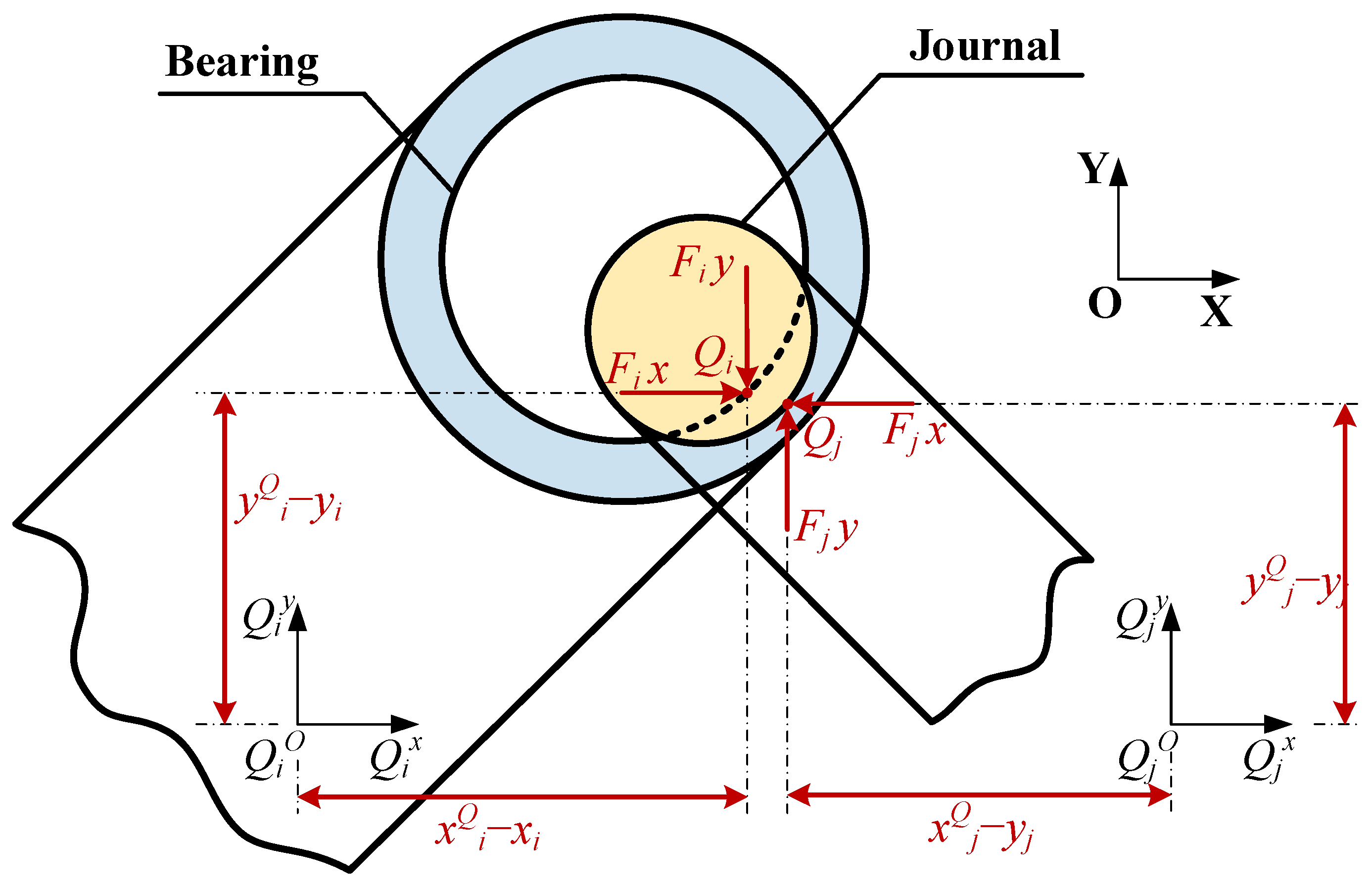
The normal contact force F N and tangential contact force F T generated by the collision between the bearing and journal both act on the contact point, and their effects on the generalized force matrix g can be obtained by projecting them onto the X and Y directions, as shown in Figure 5.
The force and moment on the bearing can be written [42]:
F i = F N + F T
M j = ( x j Q x j ) F j y ( y j Q y j ) F j x
The force and moment on the journal can be written:
F j = F i
M j = ( x j Q x j ) F j y ( y j Q y j ) F j x
where:
F k is the contact force on the bearing (journal), k = i , j ;
F k x is the component of the contact force on the bearing (journal) in the generalized coordinate with respect to the x-axis, k = i , j ;
F k y is the component of the contact force on the bearing (journal) in the generalized coordinate with respect to the y-axis, k = i , j ;
M k is the moment applied to the rocker arm (connecting rod), k = i , j ;
x k Q is the horizontal coordinate of the collision point in the local coordinate system of the bearing (journal), k = i , j ;
y k Q is the vertical coordinate of the collision point in the local coordinate system of the bearing (journal), k = i , j .
The final multi-body dynamic equation for the clearance containing the revolving joint is:
( M Φ q T Φ q 0 ) ( q ¨ λ ) = ( g + F c γ 2 α Φ ˙ β 2 Φ )
where F c is the contact force matrix of the clearance joint.

2.4. Contact Force Modeling of Revolving Joint with Clearance

2.4.1. Normal Contact Force Model

The L-N contact force model is one of the more widely used methods for calculating the normal contact force, which assumes that the interaction force between the impacting objects is continuous, which coincides with the actual contact and collision situation. Therefore, the L-N normal contact force model is used in this paper to calculate the normal contact force F N of the bearing and journal [8,31]:
F N = K δ n + D δ ˙
where K is the generalized contact stiffness coefficient of the bearing and journal in the joint, and D is the hysteresis damping factor.
The generalized contact stiffness factor K can be calculated by:
K = 4 3 ( h i + h j ) R i R j R i R j
where the material parameter h k ( k = i , j ) is calculated by:
h k = 1 v k 2 E k
where v k is Poisson’s ratio of bearing and journal materials, and E k is Young’s modulus of the bearing and journal material.
The hysteresis damping factor D is calculated by:
D = 3 K δ n ( 1 C r 2 ) 4 v 0
where C r is the coefficient of recovery of contact between the bearing and journal, and v 0 is the initial collision speed of the bearing and journal.

2.4.2. Tangential Contact Force Model

A tangential friction model is used to describe the tangential contact characteristics of the clearance joint. In this paper, the modified Coulomb friction model is used to calculate the tangential friction [43], which can more accurately reflect the friction during contact and collision as well as the microslip phenomenon. The tangential friction is calculated as:
F T = μ ( v s ) F N
where μ ( v s ) is the dynamic friction coefficient, calculated from Equation (19):
μ ( v s ) = { μ d | v t | > v d 2 μ d [ 3 ( v t + v d 2 v d ) 2 2 ( v t + v d 2 v d ) 3 1 2 ] v s | v t | v d μ d + ( μ s μ d ) ( v t v s v d v s ) 2 ( 3 2 ( v t v s v d v s ) ) | v t | < v s
where v t is the relative sliding speed of the bearing and journal at the point of collision, μ d is the sliding friction coefficient, μ s is the static friction coefficient, v s is the static friction critical speed, and v d is the maximum dynamic friction critical speed.

3. Wear Calculation for Revolving Joint with Clearance

In this section, the wear of the clearance joint will be analyzed based on the Archard model. It can be expressed [10]:
V s = k F N H
where V is the volume of wear, s is the relative sliding distance, K is the dimensionless wear coefficient, H is the hardness of the softer material, and K H = k / H is the wear rate.
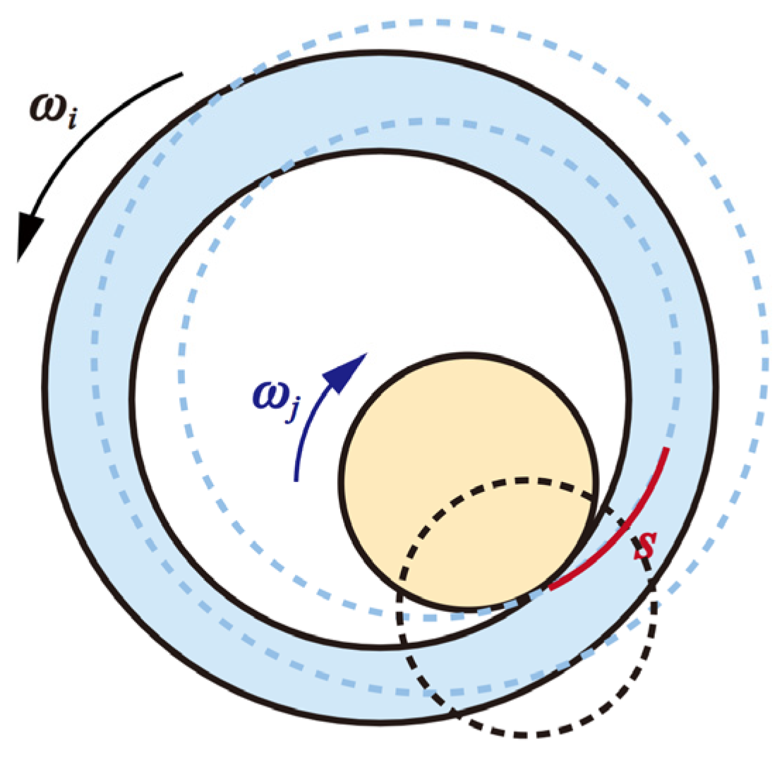
The relative sliding distance schematic is shown in Figure 6, and the calculation equation is Equation (30):
s = ( l i × ω i + l j × ω j ) d t
where l i ,   l j are the lengths of the connecting rod of the bearing and journal, respectively. ω i ,   ω j are the angular velocities of the bearing and journal, respectively.
Both sides of Equation (30) are simultaneously divided by the actual contact area A and can obtain:
h s = k p H × A
h indicates the wear depth, which is related to the contact collision force. The other parameters are as above.
The real contact area between the bearing and journal is shown in Figure 7 and the calculation equation is shown in Equations (32) and (33) [44].
b = 1.128 × 2 × F N L × R i R j R i R j × ( h i + h j )
A = 2 × b × L
where b is half the length of the distance between the bearing and journal contact, and L is the bearing width.
Since the contact collision point of the revolving joint with clearance is constantly changing during the operation of the mechanism, the contact collision force also changes dynamically, which makes the sliding distance of the contact collision point of the bearing and journal during the operation of the mechanism also change all the time. Therefore, when actually solving the sliding distance, it is calculated by using the form of differentiation, and Equation (31) can be written:
d h d s = k p H × A
From above, it can be seen that the wear depth during the contact time period can be obtained by integrating Equation (34) over the d s time period, and, if, during the operation of the mechanism, multiple contact collisions occur in a discrete interval, the total wear depth in that interval can be written:
h = h i
Considering the geometrical properties of the revolving joint, the new radiuses of the bearing and journal after wear are:
R i f = R i + h 2
R j f = R j h 2
h is the total amount of wear, and it is considered that the bearing and journal have the same depth of wear.
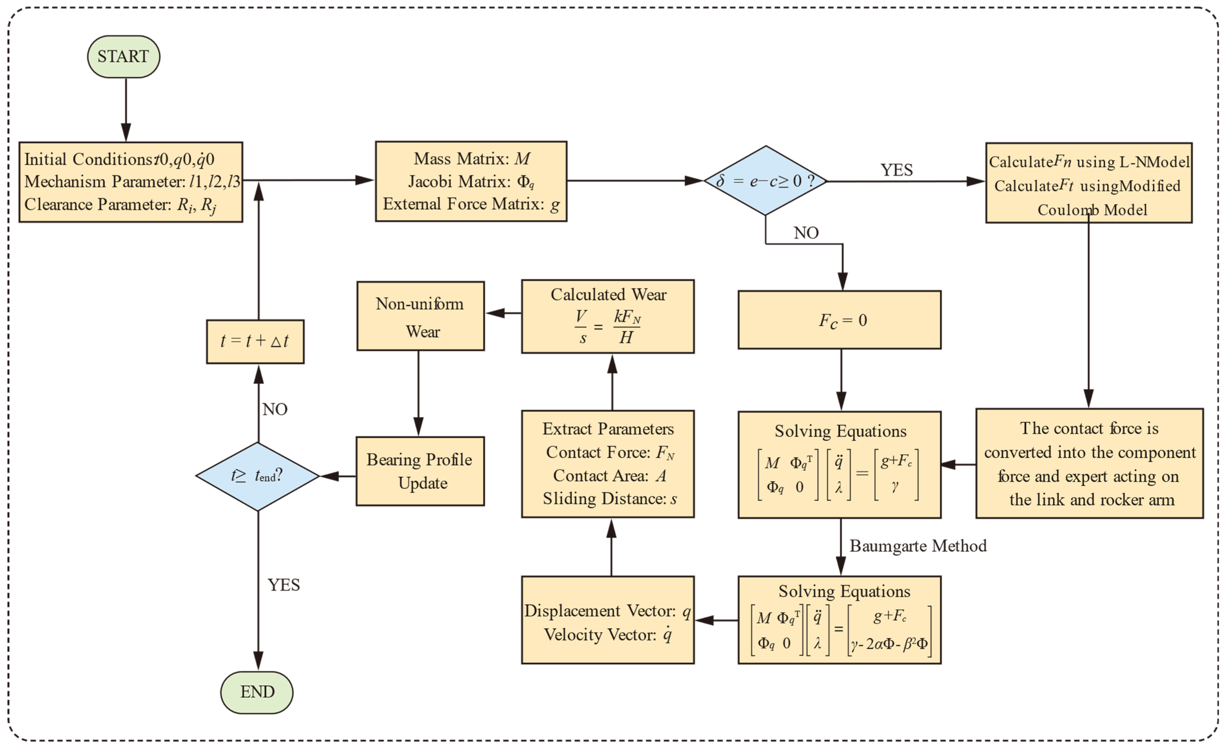
According to the above, the procedure for wear simulation of the motion mechanism in this paper is shown in Figure 8, and the main steps are summarized as follows:
Step 1: 
Set the initial parameters of the multi-body mechanism, including the dimensions of the mechanism, the displacement vector, the velocity vector, and the initial clearance, etc. and establish the dynamics equations of the ideal joint multi-body mechanism;
Step 2: 
Establish a mathematical model of the clearance joint, and judge whether or not contact occurs between the bearing and journal. If contact occurs, calculate the normal contact force and tangential contact force, and the contact force can be converted into the component force and moment applied to the connecting rods and form a matrix of contact force. Otherwise, the matrix of contact force is a zero matrix;
Step 3: 
Combine the dynamics equations of the ideal joint mechanism and the contact force matrix, and then apply the Baumgarte stabilization method to obtain the dynamic equations of the multi-body mechanism with the clearance joint and solve the dynamics response;
Step 4: 
According to the results of the dynamics solution, combine with the Archard model to calculate the wear depth of the joint, and finally obtain the wear profile of the bearing and journal;
Step 5: 
Update the wear profile of the joint in the multi-body model, perform the dynamics solution and wear calculation for the next cycle, and repeat Step 2-Step 5 until the desired number of cycles is achieved.

4. Analysis and Quantification of Uncertainty

In practice, uncertainty is ubiquitous and impacts the function of the mechanism owing to the limitations of machining and manufacturing techniques. Therefore, it is very important to identify the sources of uncertainty in flapping driving mechanism and quantify them properly. In this section, we analyze and quantify two sources of uncertainty, manufacturing tolerances and material property variations.

4.1. Manufacturing Tolerances

Since the tolerance of the dimensional parameters of components is unavoidable owing to the limitation of machine precision, the dimensional parameters are generally regarded as random variables following normal distributions [45].
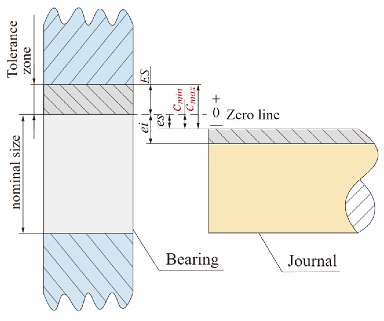
For the clearance joint, the clearance resulting from the bearing-journal fit is shown in Figure 9, which contains the tolerances. This can be expressed as the following equation:
c = 1 2 ( D d )
The mean μ c and variance σ c 2 can be expressed:
μ c = 1 2 ( T D + T d 2 e s ) ,   σ c 2 = 1 144 ( T D 2 + T d 2 )
where T D is the tolerance of the bearing diameter, T d is the tolerance of the journal diameter, and μ c , σ c 2 can be referred to as ISO 286-2 [46] according to the actual demands.
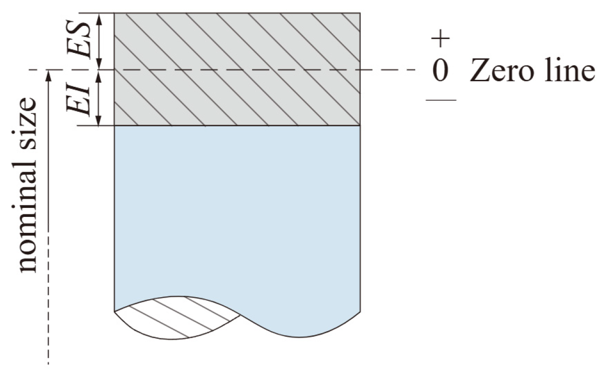
According to Figure 10, the length tolerance of the connecting rod can be written:
T = E S E I
It is assumed that the rod length tolerance is symmetric around the zero line and according to the 6-sigma principle [32], the mean and variance of the tolerance can be expressed:
μ L = 1 2 | E S + E I | = 0 ,   σ L = 1 6 T

4.2. Material Properties Variations

Uncertainties in the material manufacturing procedure can result in variations in the physical properties of the material within certain ranges [47]. The material property parameters are generally considered as random variables and follow normal distribution [48].
According to Equation (31), the material property parameters mainly consist of modulus of elasticity, Poisson’s ratio, the wear coefficient, and Brinell’s hardness of bearing and journal, and their distributions are listed in Table 1.

5. Wear Reliability Model

5.1. Reliability Function with Uncertainty

Consideration of the effect of uncertainty, the main failure mode of the flapping driving mechanism with wear, is that the depth of the non-uniform wear of the bearing exceeds the allowable wear depth, and thus breakage occurs, leading to the functional failure of the mechanism, and the failure function is:
G = δ 0 δ max ( x 1 , x 2 , , x n )
where δ 0 is the wear allowance of the bearing, and δ m a x ( x 1 , x 2 , , x n ) is the maximum wear depth of the bearing considering uncertainty.
The method of defining the allowable wear of the joint is according to the reference [49]. In general, accuracy demands are taken as δ m a x ( x i ) = 0.009 ~ 0.018 D when the nominal diameter is expressed in D . Without detailed data, it is suggested that the parameters of the joint δ m a x ( x i ) be taken as μ δ m a x 0.01 D , σ δ m a x 0.0002 ~ 0.0005 D .
Therefore, the failure probability of the mechanism can be expressed as follows:
P f = P ( δ 0 < δ max ( x 1 , x 2 , , x n ) ) = P ( G < 0 )

5.2. AK-MCS Method

In the AK-MCS method, to avoid the occurrence of neighboring training points and to improve the combination of homogeneity and randomness without computing the real performance function of the Monte Carlo sample points N m c , the Monte Carlo sample points N m c are re-sampled by the Latin hypercube sampling method [22]:
x i , j = F X j 1 ( i 0.5 N )
where N is the number of intervals, and F X j 1 ( · ) is the inverse cumulative distribution function of the random variable.
To improve the uncertainty of the simulation accuracy of the Kriging model, the sample points where the predicted signs are most likely to be mistaken are added to the experimental design. The U learning function is used to select these potential training points. The equation of the U function is expressed as follows [21]:
U ( x ) = | G ^ ( x ) | σ ^ ( x )
where U ( x ) is an indicator of the predicted value at the point x , and G ^ ( x ) and σ ^ ( x ) are the mean and variance of the Gaussian process, respectively.
The stopping criterion for the active learning Kriging modeling process is:
U m i n ( x ) U l i m i t
where U l i m i t as the learning function indicator value threshold, indicates that the probability of predicting all sample point signs properly using Kriging is at least Φ ( U l i m i t ) ; for example, when U m i n ( x ) = 2 , the probability that all sample point signs are right is at least Φ ( U l i m i t ) = 0.977 .
With the Kriging model established, the Monte Carlo method is applied to obtain the failure probability of the flapping driving mechanism:
P f N f N m c
where N f is the number of sample points for G < 0 , and N m c is the total number of sample points for the Monte Carlo simulation. The coefficient of variation of the probability of failure is:
δ P ^ f = 1 P ^ f ( N m c 1 ) P ^ f
If the coefficient of variation δ P ^ f < 0.05 , then the number of sample points overall should be added.
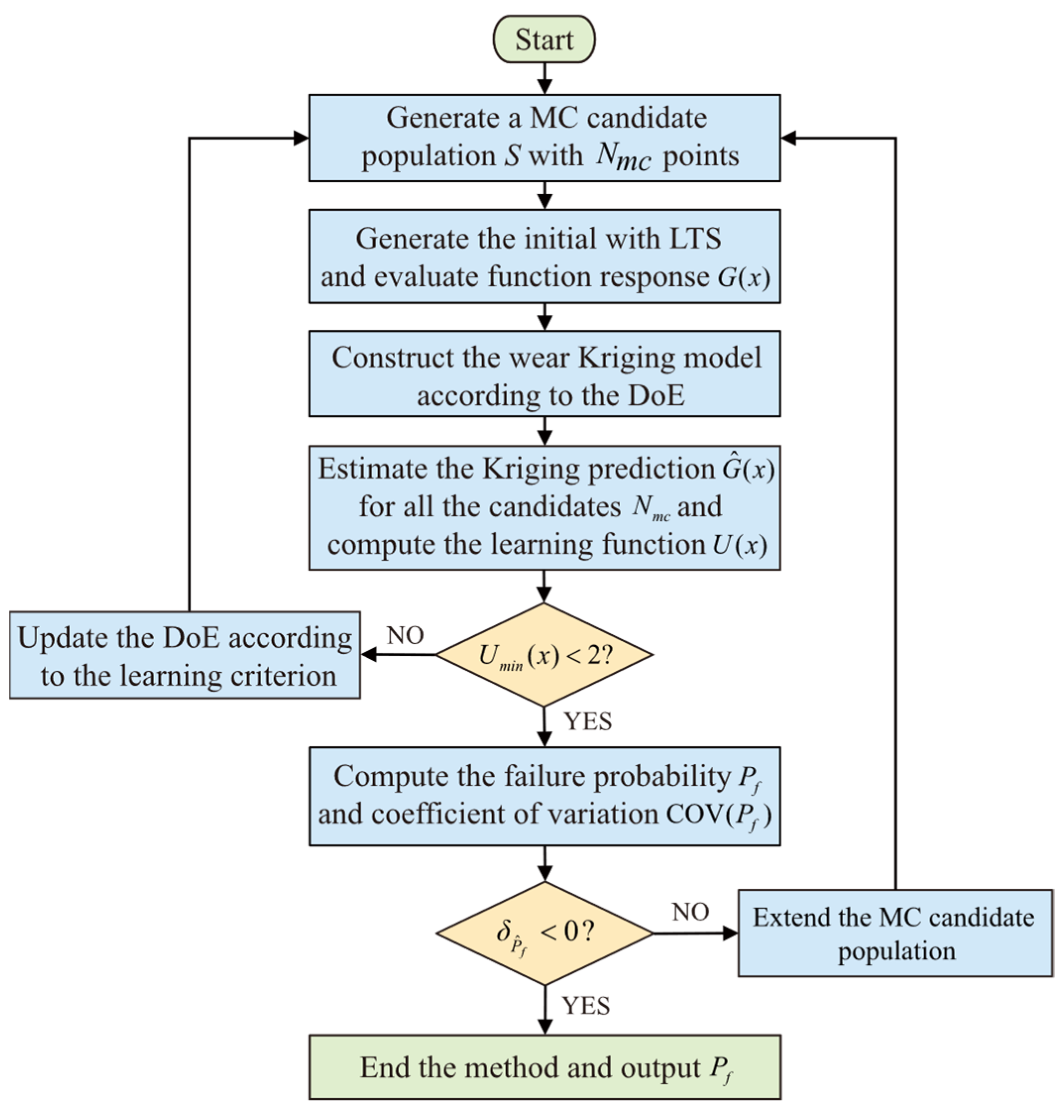
The AK-MCS method is shown in Figure 11 and the main steps are as follows:
Step 1: 
Generate a candidate population of sample points N m c based on the probability distribution of the random variables;
Step 2: 
Generate initial sample design points by random sampling in the sample space [ μ x 5 σ , μ x + 5 σ ] according to the Latin Hypercubic Sampling Method, and calculate the corresponding function values G ( x ) , which are used as the experimental initial design of the Kriging model;
Step 3: 
Use the DACE toolbox of MATLAB (R2024b) to build the experimental design Kriging model, with the Gaussian model selected for the correlation model and a constant for the regression model;
Step 4: 
Estimate the Kriging response G ^ ( x ) and variance σ ^ ( x ) of all candidate samples N m c . Calculate the learning function for all candidate sample points N m c ;
Step 5: 
If U m i n < 2 , find the optimized training point, that is, the sample point with the smallest value of the U function, and update the Kriging model and rerun Step 3. If U m i n 2 , continue to Step 6;
Step 6: 
Calculate the failure rate and coefficient of variation according to Equations (47) and (48). If the coefficient of variation δ P ^ f < 0.05 , the candidate samples N m c should be increased and Step 1 should be restarted;
Step 7: 
End the AK-MCS process and output the failure probability of the mechanism P f .

6. Results and Discussion

In this section, the flapping driving mechanism will be modeled dynamically, considering uncertainty as an example to obtain the non-uniform wear characteristics of the joint and compare it with the practical experimental joint wear results, and, finally, the wear reliability analysis of the mechanism will be conducted.

6.1. Wear Characteristics of Flapping Driving Mechanism

6.1.1. Dynamics Modeling

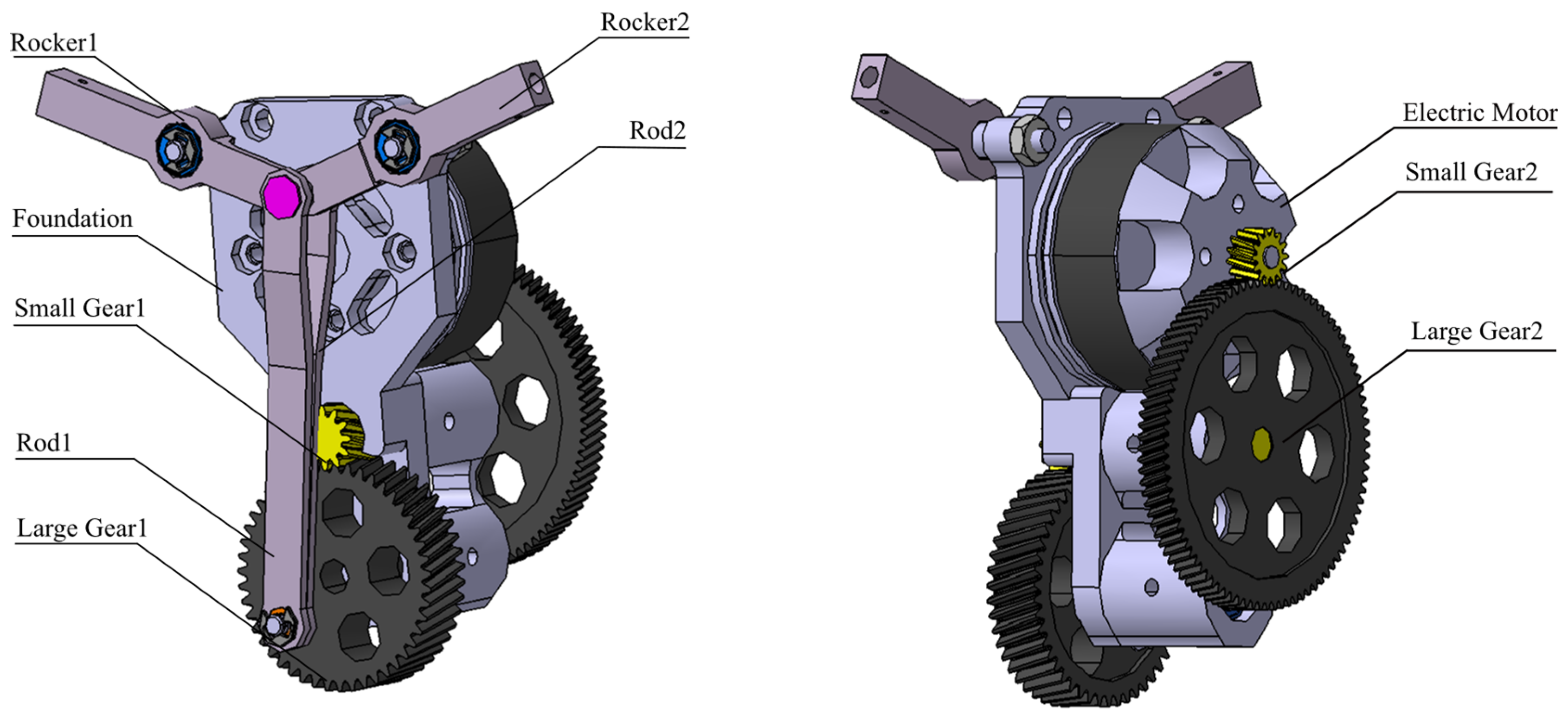
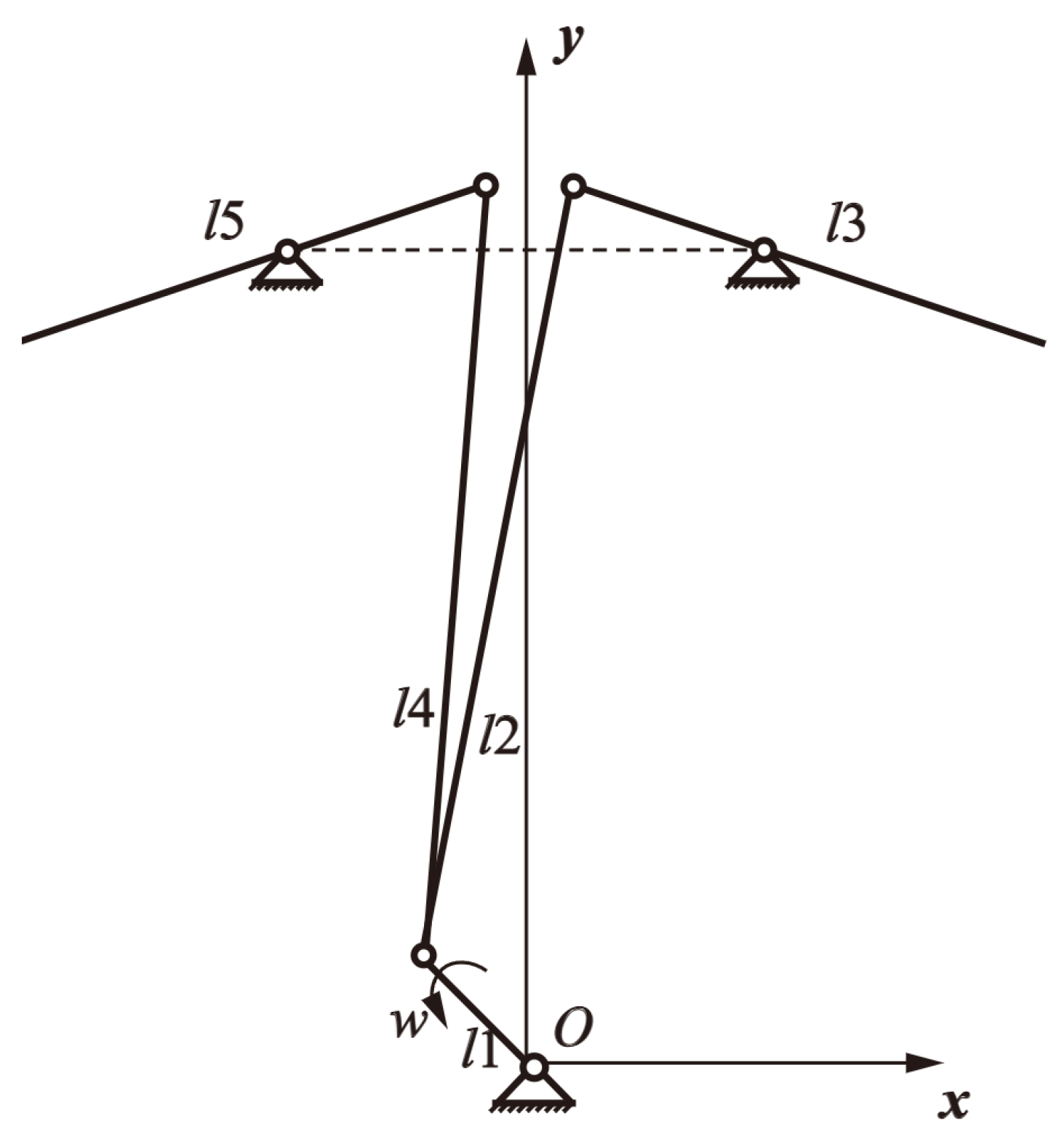
The flapping wing mechanism mainly consists of a motor, seat, gears, crank, connecting rods, and rocker arms, which are modeled as shown in Figure 12.
In order to model, the flapping wing driving mechanism is simplified to a single crank double rocker mechanism, where O is the point for the generalized coordinate origin, as shown in Figure 13. Driven by the driving motor, the driving gear drives the crank l 1 to rotate counterclockwise at the speed of ω = 480   r / min , and the driving rod l 2 , l 4 drives the rocker arm l 3 , l 5 to realize the up and down reciprocating motion of the rocker arm.
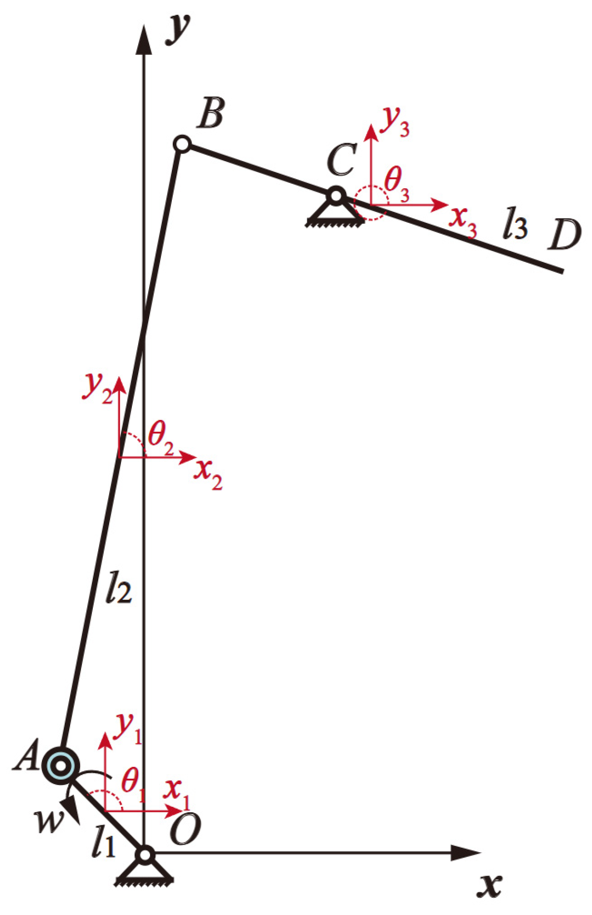
The single crank double rocker mechanism in the normal operation process is the mechanism for the left and right approximate symmetry. In order to shorten the calculation time, this paper only takes the right crank rocker for analysis. The simplified model is shown in Figure 14, where joint A is the clearance joint and point O is the origin of the global coordinate system.
The elements used in the simulation are shown in Table 2, Table 3 and Table 4.

6.1.2. Practical Experiment

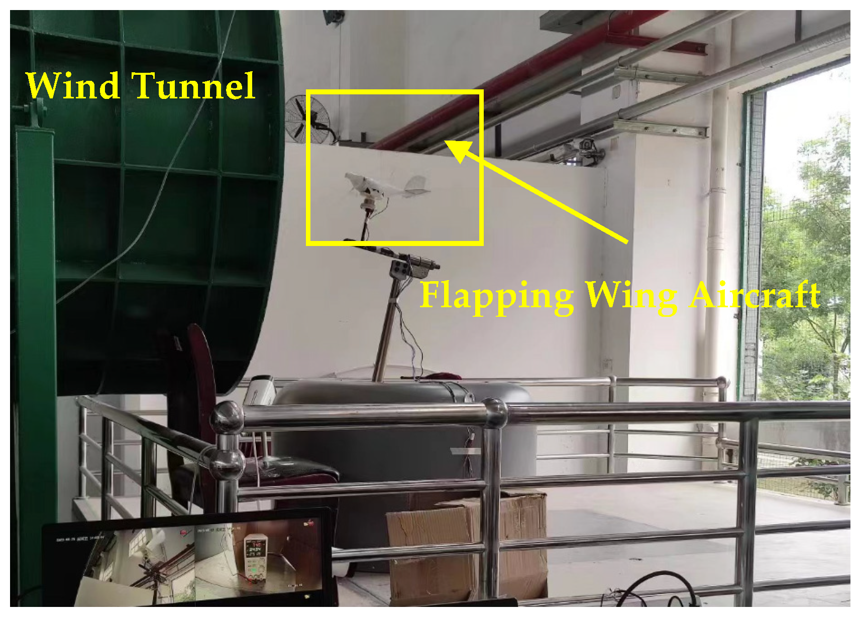
Meanwhile, we conducted practical wind tunnel experiments on four flapping wing aircrafts to obtain the wear characteristics of the clearance joint. The whole experiment was carried out at room temperature to study the joint wear of a flapping wing aircraft under steady incoming flow conditions from a normal operation to mechanism failure. And the material of the journal and bearing were stainless steel and titanium alloy, respectively. The dimensions and quality parameters of the flapping wing mechanism for the practical experiment were the same as those of the simulation experiment, as described in Section 6.1.1.
The key points of the experiment are as follows:
  • Fix the flapping wing driving mechanism together with its specialized hull on the specialized wind tunnel experimental platform, adjusting the angle of attack to 10° and setting the incoming speed of the wind tunnel to 10 m/s;
  • Wait for the wind speed in the wind tunnel to stabilize, and then activate the flapping wing aircraft. Adopt a DC voltage to supply power to the flapping wing aircraft, and operate it stably at the speed of 480 r/min in the experiment;
  • Use high-definition cameras to monitor the operation of the mechanism in real-time;
  • Use a magnifying glass and microscope at intervals to observe the wear of the mechanism joint until the mechanism fails.
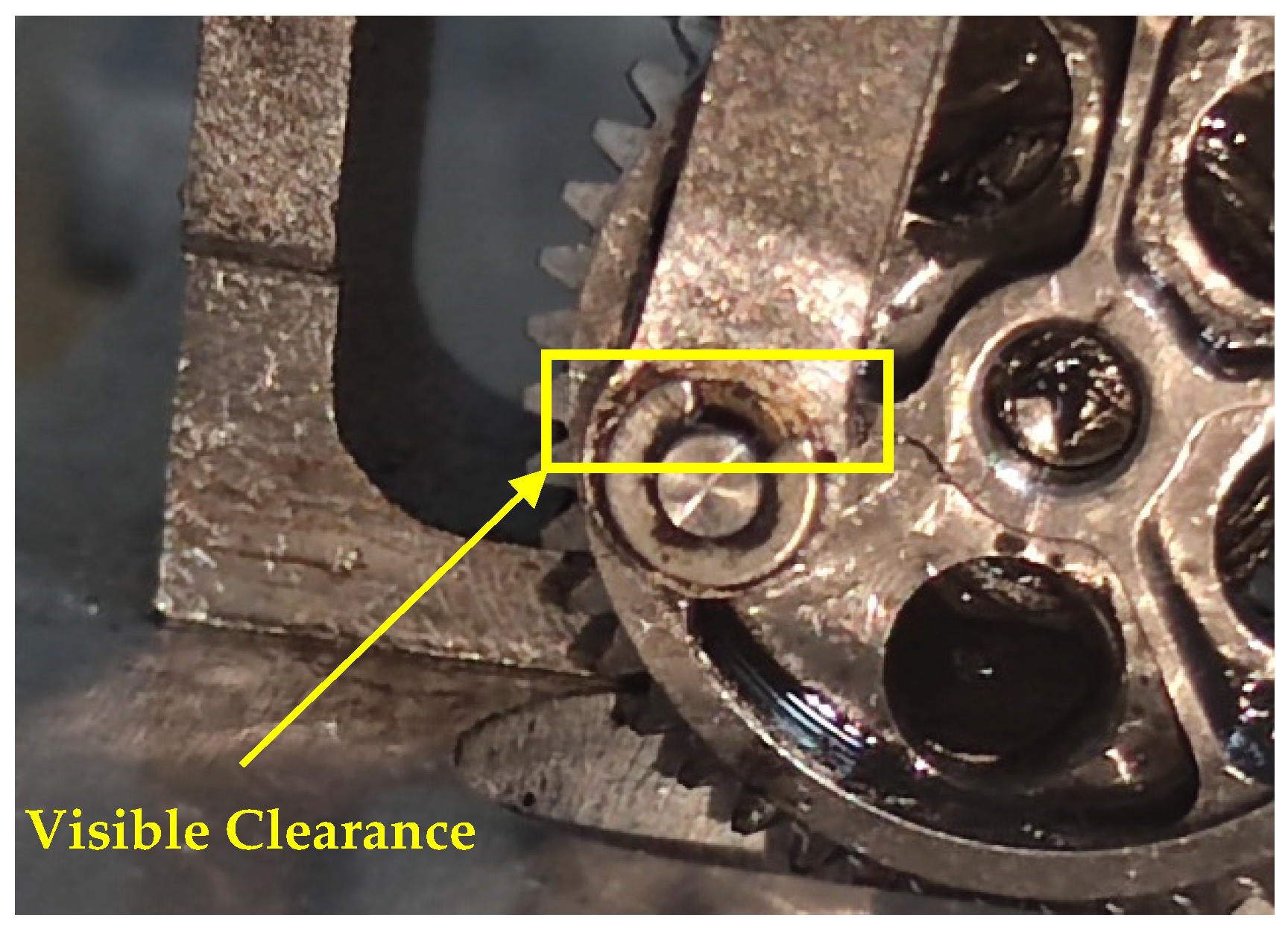
The experimental stand is shown in Figure 15. And when the mechanism is operated to failure, a visible clearance is shown in joint A , as shown in Figure 16.

6.1.3. Dynamic Wear Characteristics

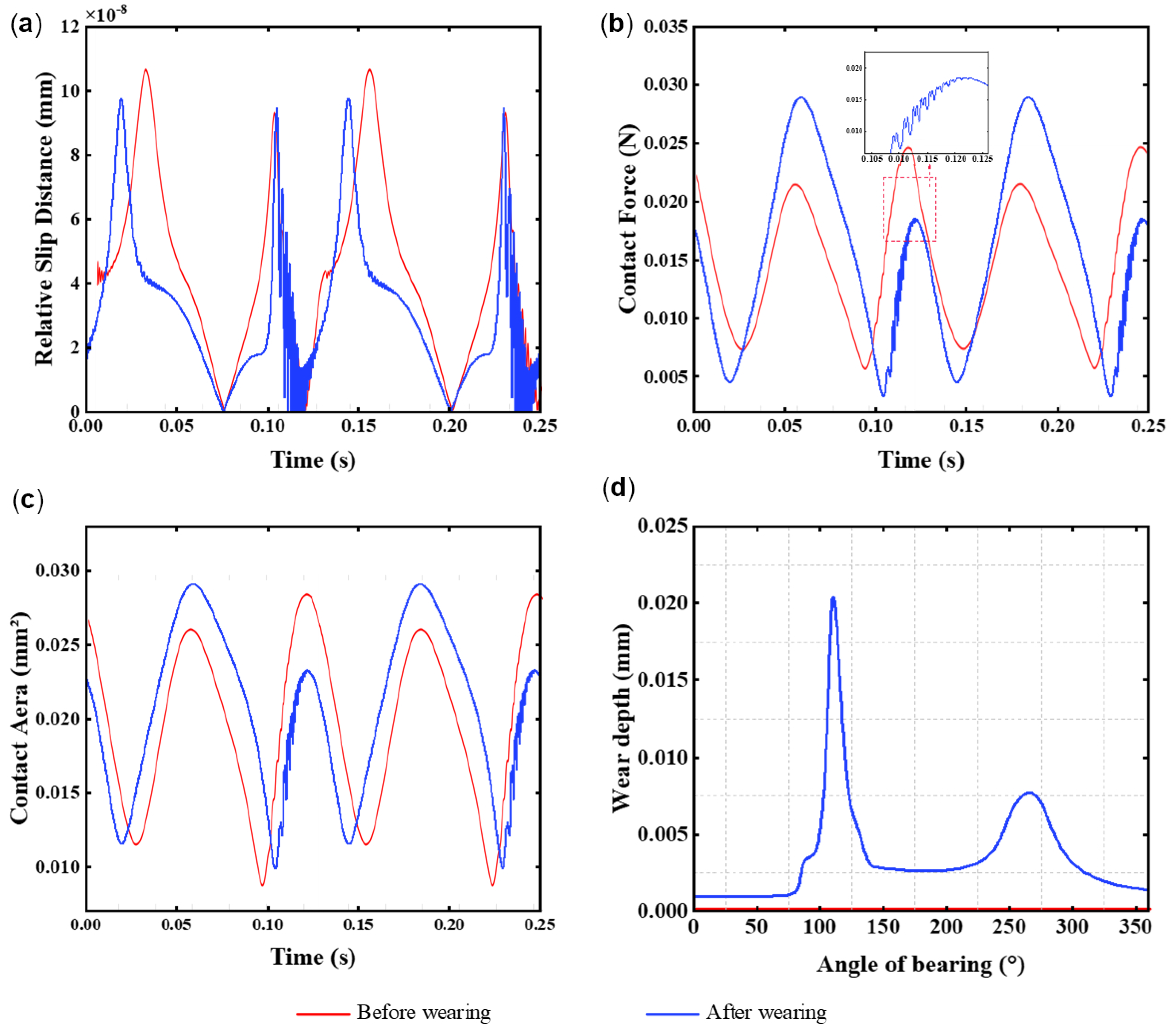
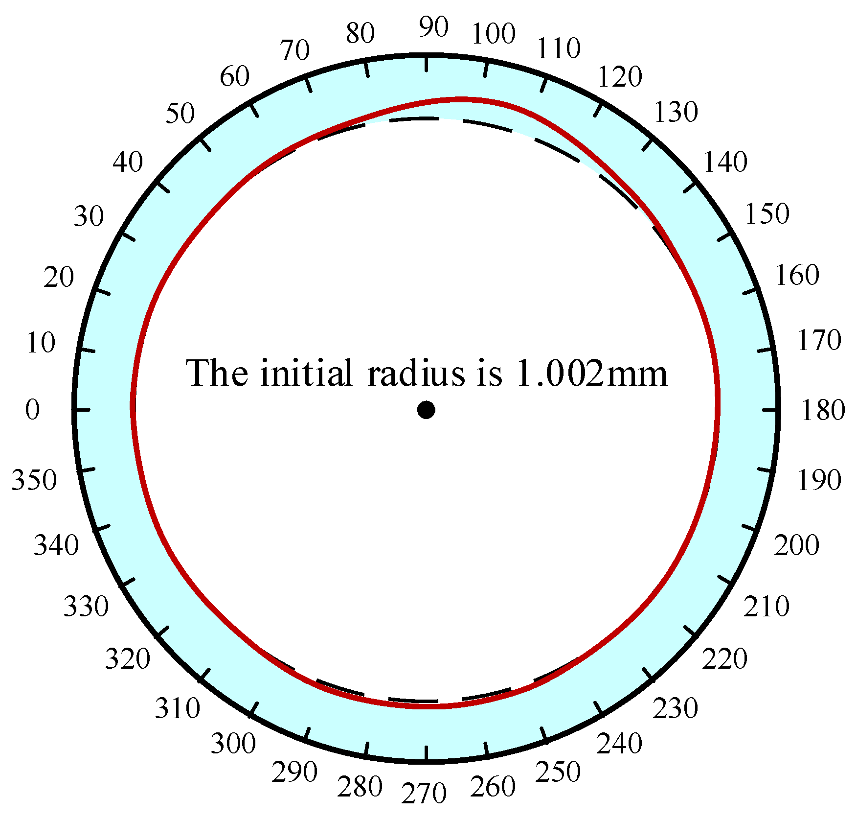
The dynamics simulation of the flapping driving mechanism with clearance revolving joint was conducted to obtain the wear depth of the mechanism after 400,000 cycles of operation, as shown in Figure 17. In the case of relative slip distance, since there was some fluctuation in the initial contact, some values were omitted. Regarding the leftmost point of the inner bearing as the starting point of wear, it was marked as 0°, and then the inner bearing was marked in a clockwise direction up to 360°. The wear depth of the bearing achieved the first peak in the 110° region, and the maximum wear depth was 0.0249 mm, which was about 1.66% of the radius of the bearing. After that, the wear depth remained at a low value until it reached a second peak of 0.0087 mm in the 310° region. The profile of the bearing after 400,000 cycles of operation of the mechanism is shown in Figure 18. It shows that the depth of wear is concentrated at the top and bottom vertices of the bearing. Figure 19 shows the bearing figure after the mechanism has failed after 576,000 cycles of operation; the red line is the initial profile of the bearing. We can observe that the bearing wear profiles of the four experimental parts are almost uniform. Comparison of Figure 18 and Figure 19 indicates that the wear results obtained from the simulation are consistent with the practical experimental bearing wear tendency.

6.2. Define the Allowable Wear of the Joint

According to the Section 6.1.3, the diameter of the bearing of joint A is 3 mm, which corresponds to a wear allowance of the bearing being 0.03 mm. This means when the maximum wear value of the bearing exceeds 0.03 mm, i.e., G < 0 , the mechanism fails.

6.2.1. Define the Random Variables

Based on the dynamic characteristics of flapping driving mechanism, the bearing radius R j , joint clearance c , length of crank and connecting rod l 1 . l 2 , rocker arm l B C , and the material properties of the journal and bearing were taken as random variables, and their distributions are shown in Table 5 and Table 6.

6.2.2. Reliability Analysis

In this section, 13 random variables were extracted from 100,000 Monte Carlo samples using the Latin Hypercubic Sampling method, totaling 20 groups, and the maximum wear values of 20 joints were obtained through dynamic simulation. The maximum wear values corresponding to all the Monte Carlo samples were deduced using the AK-MCS method, and the reliability of the flapping driving mechanism was calculated.
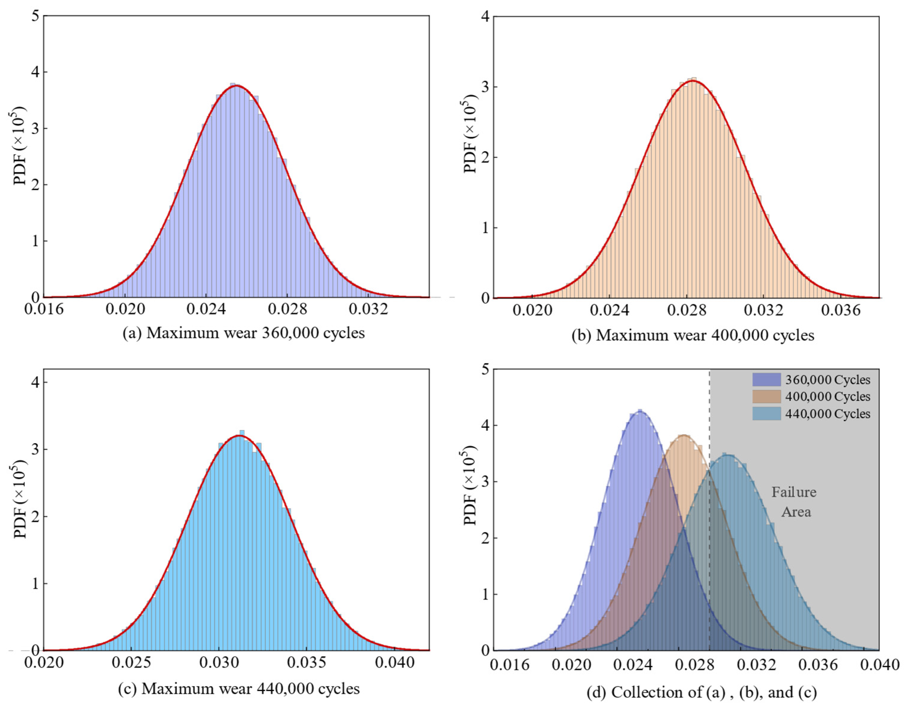
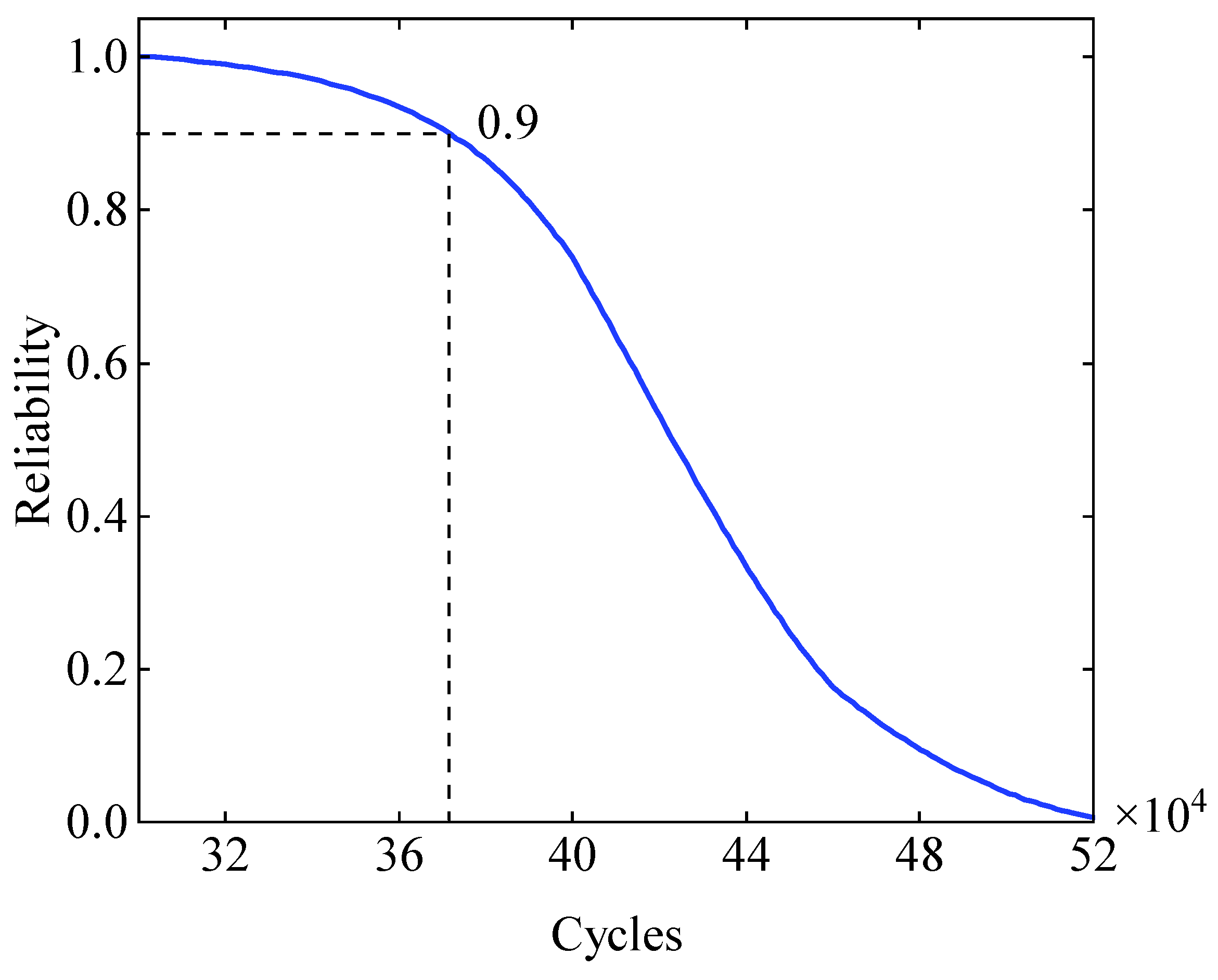
Figure 20 shows the maximum wear probability distribution of the joint for 360,000 cycles, 400,000 cycles, and 440,000 cycles of the driving mechanism, and the mean of the maximum wear value distribution increases gradually with the increased operation cycles, which are 0.0256 mm, 0.0285 mm, and 0.0313 mm, respectively. Figure 21 shows the curve of the reliability of the driving mechanism with the operating cycle. When the mechanism is running 36,000 cycles, the reliability is 0.9780; when it is running 400,000 cycles, the reliability is 0.739; when it is running 420,000 cycles, the reliability is 0.538; and when it is running 520,000 cycles, the reliability is 0.006, which is basically reduced to zero. Based on experience, the acceptable mechanism reliability was set to 0.9, which corresponds to an operating cycle of approximately 371,640 and an operating time of approximately 12.90 h. It is considered that the mechanism reliability is unacceptable beyond this time.

6.2.3. Reliability Sensitivity Analysis

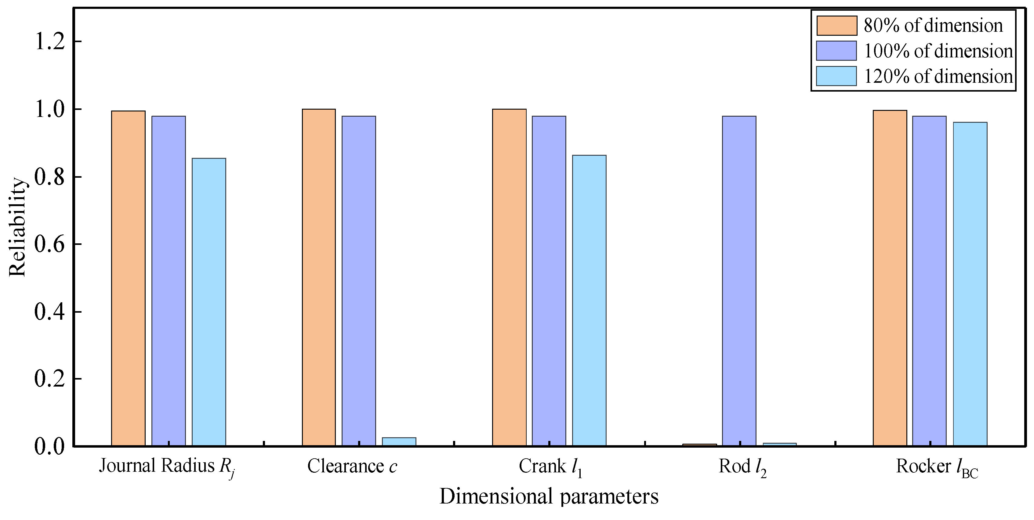
In this section, the mean values of each random variable were modified to 80% and 120% of the original values while keeping the other parameters constant to study the effect of these modifications on the reliability of the driving mechanism for 360,000 cycles of operation. The results of the reliability sensitivity analysis for manufacturing tolerances are shown in Figure 22.
According to Figure 22, the ranking of reliability sensitivity of component manufacturing tolerances is as follows: Length of connecting rod > Size of clearance > Radius of journal > Length of crank > Length of rocker. It can be observed that the reliability sensitivity of the bearing radius and the dimensions of the crank and the rocker arm are relatively little. But the increased clearance of the joint leads to a sharp decrease in the reliability, which has a great impact on the reliability of the mechanism. Both positive and negative deviations of the connecting rod dimensions result in a reduction of the reliability of the mechanism to zero, which greatly impacts the reliability of the mechanism. Based on the above, the precision of the dimensions of the connecting rod and the clearance of the joint requires particular attention, which can be supported by using the coordinate measuring machine when necessary.
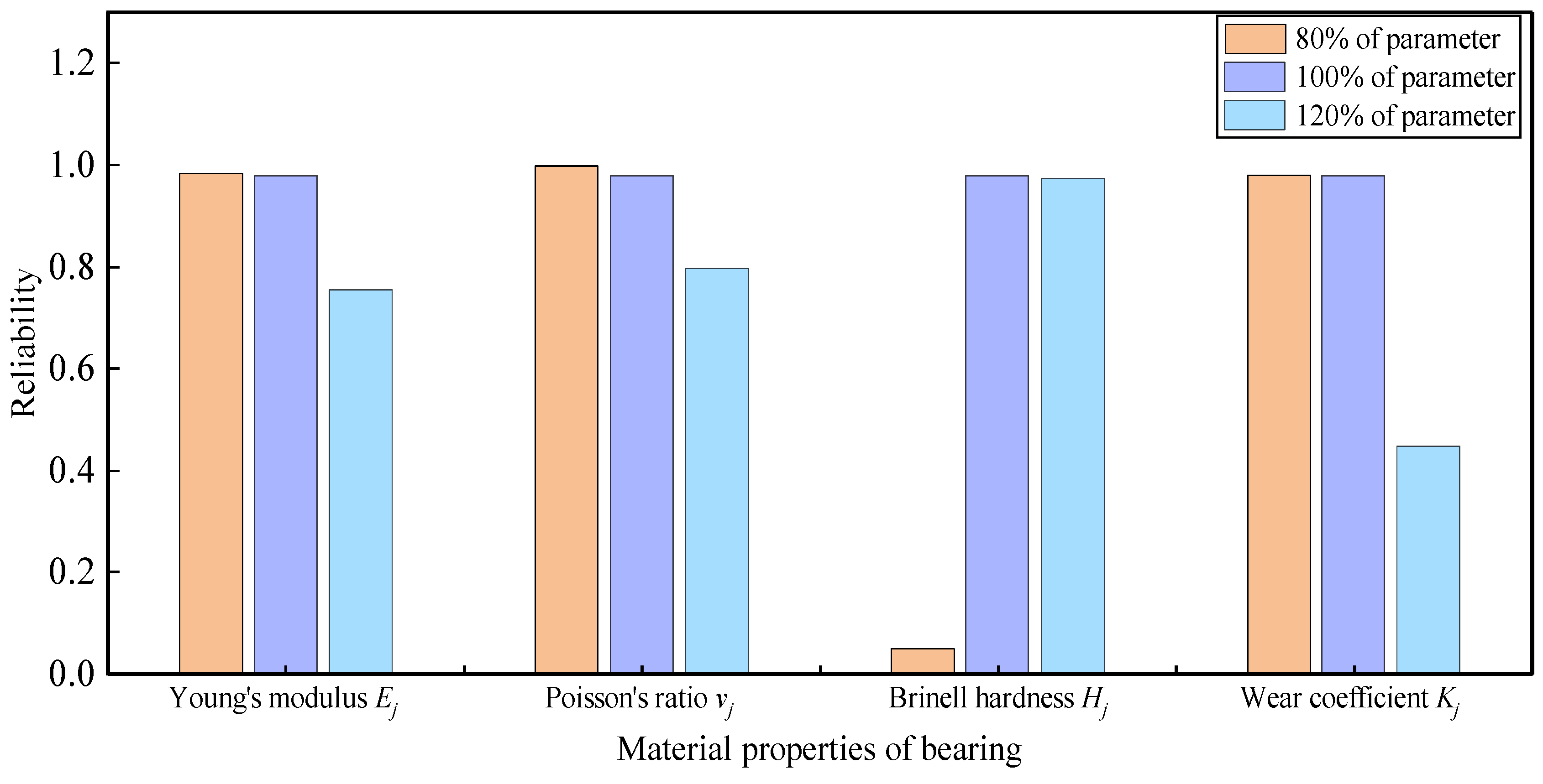
The results of reliability sensitivity analysis for material properties are shown in Figure 23 and Figure 24. From Figure 23, the reliability sensitivity of the means of journal material properties can be sorted as follows: Brinell hardness > Young’s modulus > Wear coefficient > Poisson’s ratio. From Figure 24, the reliability sensitivity of the means of the bearing material properties can be sorted in the following way: Brinell hardness > Wear coefficient > Young’s modulus > Poisson’s ratio. Based on the above results, we can know that the materials of the journal and bearing with higher Brinell hardness, lower Young’s modulus, lower Wear coefficient, and lower Poisson’s ratio could be prioritized to improve the reliability of the flapping driving mechanism.

7. Conclusions

The flapping-wing aircraft driving mechanism is a critical component that significantly impacts flight performance, as its failure directly renders the aircraft inoperable. Based on multibody dynamics and the Archard wear model, this study analyzed the wear characteristics of flapping-wing driving mechanisms considering joint clearance uncertainties and calculated their wear-induced reliability. In the context of rapidly advancing UAV technology, the findings of this research hold substantial importance for enhancing the reliability and durability of unmanned aerial systems. The insights gained apply not only to flapping-wing aircrafts but also to other UAV types, offering a universal framework to improve wear reliability in mechanical systems through optimized clearance management and wear prediction methodologies. Future studies could extend this framework to incorporate environmental factors, such as thermal cycling-induced material expansion, humidity-driven corrosion effects, and fatigue cracking under cyclic loading conditions, which collectively influence wear mechanisms in real-world operational environments.
The study begins by establishing a dynamic model of the flapping driving mechanism using the L-N contact model and a modified Coulomb friction model, considering the clearance joint’s intervals along its perimeter. The results revealed that the maximum wear depth of the joint reached 0.0249 mm at 400,000 operation cycles, equivalent to approximately 1.66% of the bearing radius. These findings align closely with practical experimental outcomes, demonstrating the validity and reliability of the proposed methodology in predicting wear characteristics within flapping wing aircraft systems.
Furthermore, based on the wear of the clearance joint, a wear reliability model was established, incorporating uncertainties through the use of the AK-MCS method. The results indicated that the mechanism can operate for a maximum of 371,640 cycles, corresponding to an operating time of approximately 12.90 h, when the acceptable reliability threshold is set at 0.9. This outcome underscores the importance of understanding and predicting wear-related failures in UAV systems, where operational longevity is crucial for mission success.
In the final analysis, the reliability sensitivity of random variables associated with manufacturing tolerances and material property parameters was evaluated. The findings highlighted that the length tolerances of the connecting rod and clearance joint, as well as the parameter tolerances of Brinell hardness and wear coefficient, significantly influence the wear reliability of the driving mechanism. These results emphasize the need for meticulous control over these variables during the manufacturing and assembly phases to ensure optimal performance and safety in drone applications.
In conclusion, this study has provided valuable insights into the wear characteristics and reliability of flapping wing driving mechanisms, with direct relevance to the development and optimization of advanced UAV systems. By addressing wear-related issues, this research contributes to enhance the operational capabilities, safety, and longevity of drones, particularly in scenarios requiring high precision, stealth, and maneuverability. The findings are expected to inform future advancements in drone technology, enabling their continued expansion into diverse military and civilian applications.

Author Contributions

Y.J. and X.C. came up with the idea of the paper and performed the calculations using numerical simulation, X.C. completed the first draft. K.W. processed the data to generate the graphs, D.J. was in charge of the data collection and format checking. J.L. and H.P. suggested improvements to the first draft and were in charge of monitoring. All authors have read and agreed to the published version of the manuscript.

Funding

This work was supported in part by the National Natural Science Foundation of China under Grant No. 52202507 and, in part, by the Natural Science Foundation of Shaanxi Province under Grant 2024JC-YBMS-371.

Data Availability Statement

The datasets used and analyzed during the current study are available from the corresponding author on reasonable request.

Conflicts of Interest

The authors declare no conflicts of interest.

References

  1. Zhang, H.; Song, B.; Sun, Z.; Wang, L. Driving mechanism of flapping wing aircraft: Review and prospect. Acta Aeronaut. Astronaut. Sin. 2021, 42, 74–95. [Google Scholar]
  2. Flores, P.; Ambrósio, J. Revolute joints with clearance in multibody systems. Comput. Struct. 2004, 82, 1359–1369. [Google Scholar] [CrossRef]
  3. López-Lombardero, M.; Cuadrado, J.; Cabello, M.; Martinez, F.; Dopico, D.; Varela, A.L. Simulating fatigue damage on planar mechanisms considering wear in revolute joints with clearance. Mech. Mach. Theory 2024, 203, 105805. [Google Scholar] [CrossRef]
  4. López-Lombardero, M.; Cuadrado, J.; Cabello, M.; Martinez, F.; Dopico, D.; López-Varela, A. A multibody-dynamics based method for the estimation of wear evolution in the revolute joints of mechanisms that considers link flexibility. Mech. Mach. Theory 2024, 194, 105583. [Google Scholar] [CrossRef]
  5. Li, H.; Xie, J.; Wei, W. Numerical and Dynamic Errors Analysis of Planar Multibody Mechanical Systems With Adjustable Clearance Joints Based on Lagrange Equations and Experiment. J. Comput. Nonlinear Dyn. 2020, 15, 081001. [Google Scholar] [CrossRef]
  6. Lin, Y.P.; Wang, J.C.; Zhang, J.L.; An, M.X.; Jiang, S. Research on the Dynamic and Reliability of Planar Multi-Link Mechanisms with Multiple Clearances. Mech. Solids 2024, 59, 1537–1558. [Google Scholar] [CrossRef]
  7. Wei, Z.; Wang, Z.; Li, D.; Liang, D. Rigid-flexible coupling dynamic modelling and dynamic accuracy analysis of planar cam four-bar mechanism with multiple clearance joints. Proc. Inst. Mech. Eng. Part K J. Multi-Body Dyn. 2024, 238, 421–444. [Google Scholar] [CrossRef]
  8. Zhu, X.; Zhao, F.; Yang, X.; Xu, Y.; Jia, P.; Zhou, B.; Xue, S. Study on Collision Dynamics Model and Multi-Body Contact Forces of Ball Cage Flexible Joint Considering Clearance. Machines 2023, 11, 466. [Google Scholar] [CrossRef]
  9. Roupa, I.; Gonçalves, S.B.; da Silva, M.T. Kinematics and dynamics of planar multibody systems with fully Cartesian coordinates and a generic rigid body. Mech. Mach. Theory 2023, 180, 105134. [Google Scholar] [CrossRef]
  10. Zhuang, X. Time-dependent kinematic reliability of a dual-axis driving mechanism for satellite antenna considering non-uniform planar revolute joint clearance. Acta Astronaut. 2022, 197, 91–106. [Google Scholar] [CrossRef]
  11. Wang, H.; Wang, J. Dynamics and control of spacecraft solar array deployment considering physical contacts between locking mechanisms. Acta Astronaut. 2022, 195, 481–492. [Google Scholar] [CrossRef]
  12. Zhou, Z.; Zheng, X.; Chen, Z.; Wang, X.; Liang, B.; Wang, Q. Dynamics modeling and analysis of cable-driven segmented manipulator considering friction effects. Mech. Mach. Theory 2022, 169, 104633. [Google Scholar] [CrossRef]
  13. Wang, J.; Su, Y.; Subramaniam, N.A.; Pang, J.H.L. Archard model guided feature engineering improved support vector regression for rail wear analysis. Eng. Fail. Anal. 2022, 137, 106248. [Google Scholar] [CrossRef]
  14. Jia, J.; Cui, W.; Zhang, Y.; Shen, L.; Wu, H. Analysis of Uneven Wear in Driving Mechanism of Flapping-Wing UAV. In Proceedings of the 2020 IEEE International Conference on Mechatronics and Automation (ICMA), Beijing, China, 13–16 October 2020. [Google Scholar] [CrossRef]
  15. Sun, Y.; Li, Y.; Zhang, Q.; Qin, X.; Chen, K. Wear analysis and simulation of small module gear based on Archard model. Eng. Fail. Anal. 2023, 144, 106990. [Google Scholar] [CrossRef]
  16. Zhuang, X.; Yu, T.; Liu, J.; Song, B. Kinematic reliability evaluation of high-precision planar mechanisms experiencing non-uniform wear in revolute joints. Mech. Syst. Signal Process. 2022, 169, 108748. [Google Scholar] [CrossRef]
  17. Li, Y.; Yang, Y.; Li, M.; Liu, Y.; Huang, Y. Dynamics analysis and wear prediction of rigid-flexible coupling deployable solar array system with clearance joints considering solid lubrication. Mech. Syst. Signal Process. 2022, 162, 108059. [Google Scholar] [CrossRef]
  18. Jiang, S.; Wang, T.; Xiao, L. Experiment research and dynamic behavior analysis of multi-link mechanism with wearing clearance joint. Nonlinear Dyn. 2022, 109, 1325–1340. [Google Scholar] [CrossRef]
  19. Li, X.-Y.; Chen, W.-B.; Kang, R. Performance margin-based reliability analysis for aircraft lock mechanism considering multi-source uncertainties and wear. Reliab. Eng. Syst. Saf. 2021, 205, 107234. [Google Scholar] [CrossRef]
  20. Jiang, D.; Han, Y.; Wang, K.; Jiang, S.; Cui, W.; Song, B. Functional degradation reliability analysis for non-uniform wear of multi-rotating joints of mechanical structures. Eng. Fail. Anal. 2024, 157, 107934. [Google Scholar] [CrossRef]
  21. Afshari, S.S.; Enayatollahi, F.; Xu, X.; Liang, X. Machine learning-based methods in structural reliability analysis: A review. Reliab. Eng. Syst. Saf. 2022, 219, 108223. [Google Scholar] [CrossRef]
  22. Wang, W.; Shen, G.; Zhang, Y.; Zhu, Z.; Li, C.; Lu, H. Dynamic reliability analysis of mechanical system with wear and vibration failure modes. Mech. Mach. Theory 2021, 163, 104385. [Google Scholar] [CrossRef]
  23. Wang, T.; Chen, Z.; Li, G.; He, J.; Shi, R.; Liu, C. Adaptive Kriging-based probabilistic subset simulation method for structural reliability problems with small failure probabilities. Structures 2024, 70, 107726. [Google Scholar] [CrossRef]
  24. Prentzas, I.; Fragiadakis, M. Quantified active learning Kriging model for structural reliability analysis. Probabilistic Eng. Mech. 2024, 78, 103699. [Google Scholar] [CrossRef]
  25. Shi, Y.; Lu, Z.; He, R.; Zhou, Y.; Chen, S. A novel learning function based on Kriging for reliability analysis. Reliab. Eng. Syst. Saf. 2020, 198, 106857. [Google Scholar] [CrossRef]
  26. Ouyang, L.; Huang, L.; Han, M. An active learning reliability analysis algorithm: Based on the perspective of Kriging prediction variance. Xitong Gongcheng Lilum Yu Shijian 2023, 43, 2154–2165. [Google Scholar] [CrossRef]
  27. Zhang, W.; Guan, Y.; Wang, Z.; Xu, H. A novel active learning Kriging based on improved Metropolis-Hastings and importance sampling for small failure probabilities. Comput. Methods Appl. Mech. Eng. 2025, 435, 117658. [Google Scholar] [CrossRef]
  28. Yuan, Y.; Au, F.T.; Yang, D.; Zhang, J. An active learning Kriging-based Bayesian framework for probabilistic structural model exploration. J. Sound Vib. 2025, 596, 118730. [Google Scholar] [CrossRef]
  29. Gong, Y.; Zhang, J.; Xu, D.; Huang, Y. Quantile-based optimization under uncertainties for complex engineering structures using an active learning basis-adaptive PC-Kriging model. Chin. J. Aeronaut. 2025, 38, 103197. [Google Scholar] [CrossRef]
  30. Zhang, S.; Gao, Y.; Yang, J. Dynamic modeling and analysis of vehicle scissor door mechanism with mixed clearance based on a hybrid contact force model. Multibody Syst. Dyn. 2024, 61, 509–538. [Google Scholar] [CrossRef]
  31. Ding, S.; Jian, B.; Zhang, Y.; Xia, R.; Hu, G. A normal contact force model for viscoelastic bodies and its finite element modeling verification. Mech. Mach. Theory 2023, 181, 105202. [Google Scholar] [CrossRef]
  32. Dong, Z.; Liang, X.; Hou, Y.; Zhang, Z. 6σ uncertainty optimisation strategy for USV navigation performance based on reliability analysis. Ocean Eng. 2022, 249, 110915. [Google Scholar] [CrossRef]
  33. Dong, X.; Sun, Y.; Wu, X.; Wang, R. Dynamic modeling and performance analysis of toggle-linkage presses considering mixed clearances and flexibility. Int. J. Non-linear Mech. 2022, 147, 104243. [Google Scholar] [CrossRef]
  34. Chen, X.; Jiang, S.; Wang, T. Dynamic modeling and analysis of multi-link mechanism considering lubrication clearance and flexible components. Nonlinear Dyn. 2022, 107, 3365–3383. [Google Scholar] [CrossRef]
  35. Chen, X.; Wang, T. Dynamic behavior analysis of rigid-flexible coupling planar mechanism considering dry clearances and lubrication clearances. J. Mech. Sci. Technol. 2023, 37, 1585–1600. [Google Scholar] [CrossRef]
  36. Zhuang, X.; Yu, T.; Sun, Z.; Song, K. Wear prediction of a mechanism with multiple joints based on ANFIS. Eng. Fail. Anal. 2021, 119, 104958. [Google Scholar] [CrossRef]
  37. Zhang, L.; Fang, Y.; Bai, G.; Tao, J. Dynamic Investigations on the Wear Behavior of a 3D Revolute Joint Considering Time-Varying Contact Stiffness: Simulation and Experiment. Chin. J. Mech. Eng. 2023, 36, 137. [Google Scholar] [CrossRef]
  38. Wang, Z.; Jin, G.; Wei, Z.; Liang, D.; Chang, B.; Zhou, Y. Research on irregular wear mechanism of planar multi-body mechanical system with multi-clearance joints. Adv. Mech. Eng. 2022, 14, 16878132221125043. [Google Scholar] [CrossRef]
  39. Hou, Y.-L.; Deng, Y.-J.; Zeng, D.-X. Dynamic modelling and properties analysis of 3RSR parallel mechanism considering spherical joint clearance and wear. J. Central South Univ. 2021, 28, 712–727. [Google Scholar] [CrossRef]
  40. Li, B.; Wang, M.S.; Gantes, C.J.; Tan, U.-X. Modeling and simulation for wear prediction in planar mechanical systems with multiple clearance joints. Nonlinear Dyn. 2022, 108, 887–910. [Google Scholar] [CrossRef]
  41. Wang, K.; Jiang, D.; Jiang, S.; Gao, Z.; Zhuang, X.; Cui, W. A Method for Predicting Non-Uniform Wear of Flapping Driving Mechanism Joint Considering Uncertainty, 1 April 2024, PREPRINT (Version 1) Available at Research Square. Available online: https://doi.org/10.21203/rs.3.rs-4176114/v1 (accessed on 10 December 2024).
  42. Flores, P.; Ambrósio, J.; Claro, J.P.; Lankarani, H.M. Kinematics and Dynamics of Multibody Systems with Imperfect Joints: Models and Case Studies; Springer Science & Business Media: Berlin, Germany, 2008. [Google Scholar]
  43. Bhalerao, K.; Issac, K.K. Simulation of impact, based on an approach to detect interference. Adv. Eng. Softw. 2006, 37, 805–813. [Google Scholar] [CrossRef]
  44. Brezeanu, L.C. Contact Stresses between Two Cylindrical Bodies—Cylinder and Cylindrical Cavity with Parallel Axes—Part II: 2D and 3D FEA Comparative Study. Procedia Technol. 2015, 19, 177–184. [Google Scholar] [CrossRef]
  45. Wang, J.; Zhang, J.; Du, X. Hybrid dimension reduction for mechanism reliability analysis with random joint clearances. Mech. Mach. Theory 2011, 46, 1396–1410. [Google Scholar] [CrossRef]
  46. ISO.286-2; Geometrical Product Specifications (GPS)-ISO Code System for Tolerance on Linear Sizes, Part 2: Tables of Standard Tolerance Classes and Limit Deviations for Holes and Shafts. ISO: Geneva, Switzerland, 2010.
  47. Ashby, M.F.J.K. Materials and Design: The Art and Science of Material Selection in Product Design; Butterworth-Heinemann: Oxford, UK, 2013. [Google Scholar]
  48. Bond, A.H.A. Decoding Eurocode 7; CRC Press: Boca Raton, FL, USA, 2006. [Google Scholar]
  49. Zhuang, B.Z.L.Y.D.; Zhang, Y.Q. Random Vibration of Structures; National Defense Industry Press: Arlington, VA, USA, 1995. [Google Scholar]
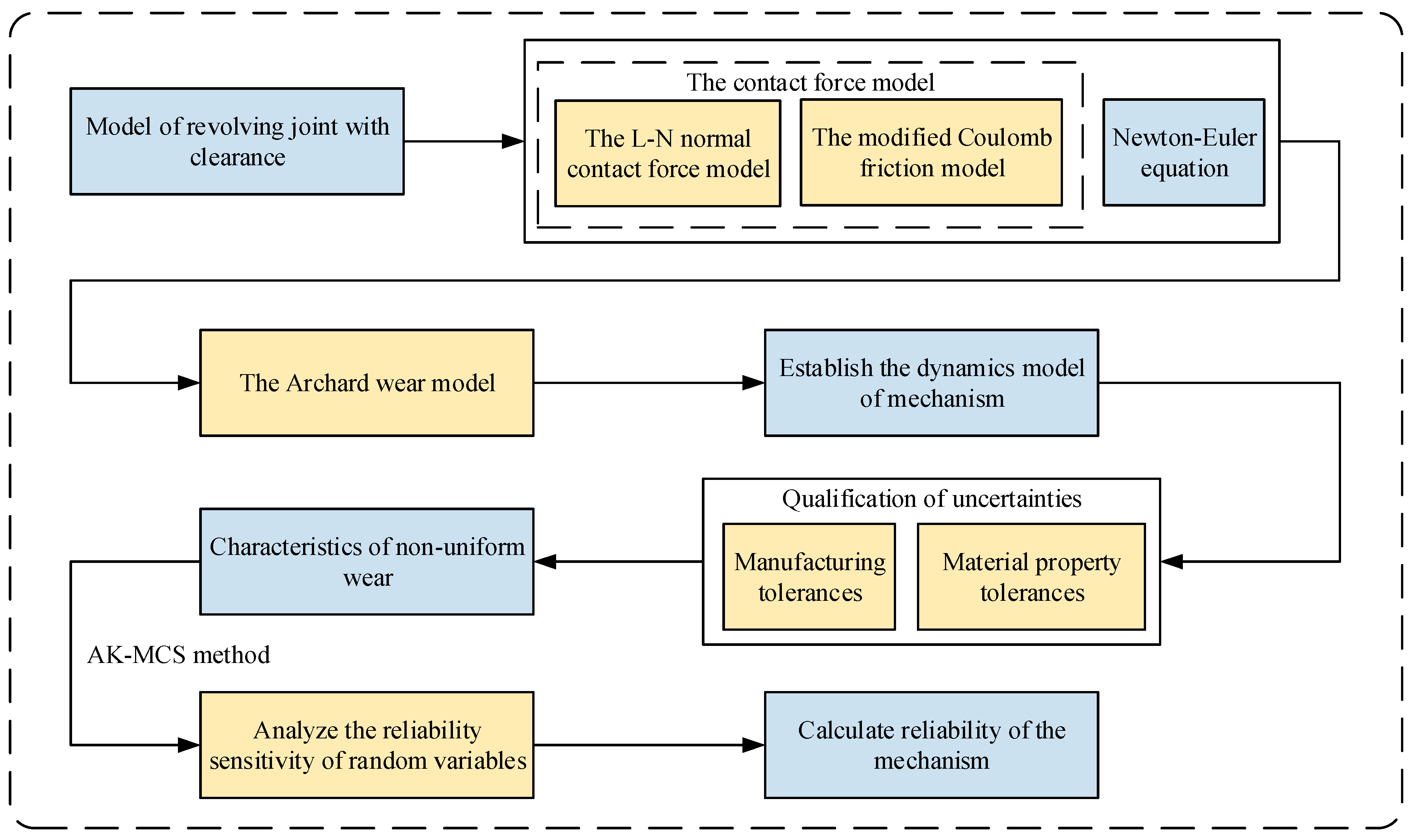
Figure 1. Flowchart of article.
Drones 09 00282 g001
Figure 2. Vector modeling of revolving joint clearance.
Drones 09 00282 g002
Figure 3. Clearance joint model.
Drones 09 00282 g003
Figure 4. Drawing of collision between bearing and journal.
Drones 09 00282 g004
Figure 5. Collision model of bearing and journal.
Drones 09 00282 g005
Figure 6. Schematic drawing of relative sliding distance.
Drones 09 00282 g006
Figure 7. Schematic drawing of contact between bearing and journal.
Drones 09 00282 g007
Figure 8. Flowchart of mechanism dynamics simulation and wear calculation.
Drones 09 00282 g008
Figure 9. Tolerance drawing for bearing and bearing fit.
Drones 09 00282 g009
Figure 10. Illustration of the tolerance zone for the length of a rod.
Drones 09 00282 g010
Figure 11. AK-MCS flowchart.
Drones 09 00282 g011
Figure 12. Flapping wing driving mechanism 3D model.
Drones 09 00282 g012
Figure 13. Simplified model of flapping driving mechanism.
Drones 09 00282 g013
Figure 14. Simplified model of crank-rocker mechanism.
Drones 09 00282 g014
Figure 15. Figure of experiment bench.
Drones 09 00282 g015
Figure 16. Wear of the joint A.
Drones 09 00282 g016
Figure 17. The wear depth data after 400,000 cycles of the flapping driving mechanism. (a) Relative slip distance; (b) contact force; (c) contact area; (d) bearing wear depth (400,000 cycles).
Drones 09 00282 g017
Figure 18. Bearing wear profile (simulation for 400,000 cycles).
Drones 09 00282 g018
Figure 19. Bearing wear profile (experiment for 576,000 cycles). (a) Experimental part 1. (b) Experimental part 2. (c) Experimental part 3. (d) Experimental part 4.
Drones 09 00282 g019
Figure 20. Distribution of maximum wear of the joint: (a) 360,000 cycles; (b) 400,000 cycles; (c) 440,000 cycles; (d) collection of (ac).
Drones 09 00282 g020
Figure 21. Curve of reliability variation.
Drones 09 00282 g021
Figure 22. Sensitivity analysis of manufacturing tolerances.
Drones 09 00282 g022
Figure 23. Sensitivity analysis of material properties of journal i.
Drones 09 00282 g023
Figure 24. Sensitivity analysis of material properties of journal j.
Drones 09 00282 g024
Table 1. Distributions of material property parameters.
ParametersDistributionsParametersDistributions
E i N ( μ E i , ( c v , E i · μ E i ) 2 ) E j N ( μ E j , ( c v , E j · μ E j ) 2 )
v i N ( μ E i , ( c v , E i · μ E i ) 2 ) v j N ( μ v j , ( c v , v j · μ v j ) 2 )
k i N ( μ k i , ( c v , k i · μ k i ) 2 ) k j N ( μ k j , ( c v , k j · μ k j ) 2 )
H i N ( μ H i , ( c v , H i · μ H i ) 2 ) H j N ( μ H j , ( c v , H j · μ H j ) 2 )
Table 2. Material properties of bearing and journal.
ElementsJournalBearing
Radius (mm)1inner: 1.002/outer:1.5
Material40 CrTitanium
Young’s modulus (N/m2)2.11 × 10111.2 × 1011
Poisson’s ratio0.2770.32
Material hardness (HB)207350
Wear coefficient (mm3/(Nm))2.1 × 10−31.2 × 10−3
Table 3. Dimensions and moments of inertia of the mechanism.
ElementsLength (m)Mass (kg)Moment of Inertia (kgm2)
Crank0.0066.77 × 10−43.17 × 10⁻⁷
Rod0.0388.71 × 10−41.44 × 10⁻⁷
Rocker0.0279.38 × 10−45.72 × 10⁻⁸
Table 4. Simulation parameters.
ParametersValues
Rocker length lBC0.012 (m)
Coordinates of point C in Figure 14(0.0115, 0.038) (m)
Restitution coefficient Cr0.9
Journal width L0.001 (m)
Crank speed ω480 (r/min)
Table 5. Distribution of dimensional parameters.
ParameterDistributions
R j N ( 1 , ( 1 × 10 3 ) 2 ) ( mm )
c N ( ( 2 × 10 3 ) , ( 1 × 10 6 ) 2 ) ( mm )
l 1 N ( 6 , ( 3.34 × 10 3 ) 2 ) ( mm )
l 2 N ( 38 , ( 2.4 × 10 2 ) 2 ) ( mm )
l B C N ( 12 , ( 1 . 8 × 10 2 ) 2 ) ( mm )
Table 6. Distribution of material properties.
ParameterDistributionsParameterDistributions
E i N ( 120 , 12 2 ) ( GPa ) E j N ( 210 , 21 2 ) ( GPa )
v i N ( 0.32 , 0.032 2 ) v j N ( 0.277 , 0.0277 2 )
k i N ( 350 , 30.5 2 ) ( HB ) k i N ( 207 , 20.7 2 ) ( HB )
H i N ( ( 1.2 × 10 3 ) , ( 1.2 × 10 4 ) 2 ) ( mm 3 / ( N · m ) ) H j N ( ( 2.1 × 10 3 ) , ( 2.1 × 10 4 ) 2 ) ( mm 3 / ( N · m ) )
Disclaimer/Publisher’s Note: The statements, opinions and data contained in all publications are solely those of the individual author(s) and contributor(s) and not of MDPI and/or the editor(s). MDPI and/or the editor(s) disclaim responsibility for any injury to people or property resulting from any ideas, methods, instructions or products referred to in the content.