Abstract
Maintenance of offshore wind farms requires the transportation of tools and spare parts in close coordination with the deployment of technicians and the cost-intensive shutdown of the wind turbines. In addition to ships and helicopters, drones are envisioned to support the offshore transportation system in the future. For cost-efficient and scalable offshore drone operations, autonomy is key to minimize the required infrastructure and personnel. In this work, we present a system architecture that integrates the key onboard capabilities for autonomous offshore drone operations: onboard mission and contingency management, en-route trajectory planning, robust flight control, safe landing, communication management, and runtime monitoring. We also present technical solutions for each of these capabilities and discuss their integration and interaction within the autonomy architecture. Furthermore, remaining challenges and the feasibility of autonomous drone operations for offshore wind farm cargo delivery are addressed, contributing to the realization of this vision in the near future. The work presented here summarizes the results of autonomous cargo drone operations within the UDW research project, a joint project between the German Aerospace Center (DLR) and the energy supplier EnBW.
1. Introduction
Cargo drones are envisioned to become a promising supplement to alleviate overstressed cargo logistics systems by increasing transport modality and efficiency as well as decreasing operating costs. The maintenance process of offshore wind farms (OWFs) is a good example of such a logistics system, as the delivery of servicing items to a large number of Wind Turbine Generators (WTGs) in the North and Baltic Seas challenges currently available delivery methods by boat or helicopter. The near future will see an immensely growing number of WTGs to support Europe’s green transition from fossil fuels to renewable energy sources. This growth poses exploding costs for WTG maintenance, threatening affordable energy prices for the consumer.
The technical feasibility and improvement in the cost-efficiency of maintenance operations through the use of cargo drones for delivery of servicing items has been researched in the project Upcoming Drones Windfarm (UDW), funded by the 7th Energy Research Program of the German Federal Ministry for Economic Affairs and Climate Action (BMWK). UDW is a research collaboration between the German Aerospace Center (DLR) and the energy provider Energie Baden-Württemberg (EnBW). Inspired by current delivery and maintenance procedures, the project evaluated how drones could be integrated into the maintenance and logistics process in the most efficient manner. A first concept for drone integration for OWF cargo delivery has been published in [1] and features the definition of a concrete delivery mission for an existing OWF operated by EnBW. The business case behind this transport mission is based on saving personal costs, e.g., pilots and operators, through full automation of all mission parts and the integration of autonomy functions into one architecture. The autonomy shall holistically provide possible adaptations to the mission, either changes in boundary conditions, e.g., permission to enter OWFs or weather, or system failures with subsequent emergency procedures. If full automation and autonomy cannot be realized, constant and thus costly human supervision of each drone would be required.
In brief, the UDW cargo mission concept presented in [1] considers a fully automated delivery of up to 200 kg of maintenance material from the mainland to an OWF. While the mission design is applicable to any UAV with Vertical Takeoff and Landing (VTOL) capabilities, we consider a helicopter configuration. The discussion about the most suitable configuration for this use case is still ongoing, though helicopters seem like a promising candidate due to their range and payload capacity. The drone shall be able to calculate a flight route including the takeoff time by itself, given a set of known boundary conditions such as weather and wind, time-frame for delivery given by the maintenance operation, and availability of the target WTG for cargo drop-off. The following takeoff and flight from mainland to an OWF shall stay well clear of other maritime traffic. Upon approach to the OWF, detailed planning of the route and approach to the WTG must be executed. This mission phase is depicted in Figure 1. As sketched in the figure, the onboard autonomy of the drone has to check for permission to enter the OWF boundaries and for clearance to approach the target WTG. Subsequently, the autonomous drone must react to the outcome of the checks. This is achieved by either choosing an approach route to the WTG, e.g., based on wind conditions or the operational state of the OWF, or by taking on a loitering pattern in case the WTG is not ready to be approached. The flight and final approach within the OWF requires safe planning of the route to stay clear of the critical infrastructure. Additionally, it should be aware of the turbulence induced by either moving rotors of operating WTGs or just the wake-flow of nacelles and towers of stopped WTGs. Adaptive planning of flight routes is needed to avoid traffic or recognize the operational status of the OWF. Therefore, the drone should be integrated into the OWF and traffic data network by defining communication protocols and systems. Additionally, stakeholder analysis in the UDW project showed that the OWF operator should have the responsibility to coordinate and control drone flights within the OWF’s borders. This shall be achieved by a request from the drone to enter the OWF, which can be granted by the personnel in the OWF’s control room.
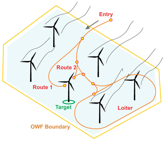
Figure 1.
An example OWF drone delivery mission would have to navigate into the wind farm after gaining permission from the OWF control room, select the most suitable route, plan a trajectory, and safely land on the target WTG; adapted from [1].
On the one hand, this mission scenario and its environment are of limited complexity with mostly pre-determined decision points and few uncertainties. On the other hand, the scenario poses specific challenges for autonomous operations that cannot be met by the current state of the art in highly automated drones. This is where the main contribution of this paper lies: we investigate the challenges and the feasibility of fully autonomous offshore drone logistics. For this purpose, we discuss recent developments of required onboard capabilities and propose technological solutions developed in the UDW project. Furthermore, we present an autonomy architecture that integrates these capabilities into a modular and extensible autonomy system. The technological cornerstones towards fully autonomous offshore drone logistics discussed in this work are as follows:
- Mission and contingency management: We explore how behavior trees can be integrated into the autonomy architecture to model the autonomous system’s behavior, schedule the execution of onboard functions, and make discrete decisions throughout the mission including the execution of contingency procedures in unforeseen or unpredictable events.
- Trajectory planning: Planning and re-planning trajectories for different phases of flight is a key onboard capability to make autonomous operation more robust against unpredictable events or changes in environmental conditions. We present a graph-based planning algorithm for en-route trajectory planning and a motion planning approach based on Model Predictive Control (MPC) that enables the drone to land safely and precisely on the WTG despite significant wind gusts.
- Flight control: The different flight phases require different types of setpoints provided by the trajectory planner en-route and the motion planner for the landing maneuver. We present a flexible controller architecture that is able to accept setpoints from either one of the planners and design helicopter controllers for robust tracking of the commanded trajectories.
- Connectivity: The integration of the drone into the traffic and OWF data networks requires the accessibility of the semantic data and also their interpretation and preparation to support autonomous decision-making. We describe a communication management component specific to the offshore drone logistics scenario.
- Runtime Monitoring: We explore the use of runtime monitoring to detect mission- and safety-critical events at various levels of the aircraft system to support autonomous decision-making and maintain the safety of the operation.
As different capabilities emerge from different scientific disciplines with a longer or shorter history of contributions, we achieve different levels of applicability. For example, classic flight control methods with a long history of research are closer to the application than emerging research fields like runtime assurance, which is currently leaving the conceptual stage. We understand that all necessary capabilities must reach a certain level of applicability to realize an autonomous mission as envisioned in the UDW cargo transport concept. Finally, we acknowledge that a use case such as the one presented in this work requires a thorough consideration of safety and certification aspects based on the appropriate regulatory frameworks. Therefore, while the methods we present in this paper are aligned with the needs of safety-critical applications, we do not claim any additional safety benefits nor do we pose this as a framework worthy of certification. Rather, it is simply intended to be a proposal for integrating different capabilities together in a framework to enable highly automated drone operations.
The remainder of this paper is structured as follows: Section 2 reviews the state of the art in onboard autonomy capabilities, autonomy architectures, and autonomous drone operations within the context of operating in offshore use cases. Section 3 presents a functional architecture for an autonomy system, highlighting the key technologies for autonomous execution of the offshore wind delivery mission. Section 3.1, Section 3.2, Section 3.3, Section 3.4 and Section 3.5 detail individual functions and proposed technologies. Then, Section 4 discusses key insights and open questions. Finally, we conclude and present future work in Section 5.
2. Related Work
Medial and scientific publications on the use and integration of drones within OWFs document a state of the art in which autonomy does not yet play a major role. Medial publications by Vattenfall in [2], Energy Denmark in [3], and DSV in [4] are good examples of OWF operators or logistics companies involved in OWF maintenance, who currently explore the possible benefits of drones to augment or replace other means of transport. All mentioned sources refer to implementations of human-supervised drone delivery for either short flights as a sky crane in [2] or prototypical long-range delivery as in [3,4]. Besides the economical considerations for the use case, the technological focus in the aforementioned works is on finding solutions to overcome the challenges of the harsh maritime environment. In [5], Banaszak et al. demonstrate approaches for proactive mission planning of Unmanned Aerial Vehicle (UAV) fleets used in offshore wind farm maintenance. However, their focus is on solving the logistics problem of routing and scheduling the UAV fleet and abstracting away from the actual technological capabilities of the drone. Their use of the term mission planning is different from the one in our work—whereas they refer to the logistics planning problem for the entire UAV fleet, we refer to the mission planning from takeoff to landing of a single UAV. We also show how such a mission could actually be executed at the software level on the drone.
To compensate for the lack of literature on autonomous offshore drone operations, we look to other application domains such as urban drone delivery and military applications for related work. First, we see that, similar to our work, other literature on Unmanned Aircraft System (UAS) autonomy tends to address the topic from the perspective of a specific set of challenges regarding the given use case. A comprehensive overview of urban drone delivery use cases as well as technical requirements regarding autonomy in this context is given by Zieher et al. [6]. Among the requirements also applicable to the offshore drone logistics scenario are the need for suitable and efficient path-planning methods, monitoring and decision-making with a focus on contingency procedures, precision landings, and reliable communication. Other requirements, however, such as environment perception or multi-UAV coordination, seem less applicable to the use case addressed in this work. An example of technical capabilities specific to the urban air delivery use case is given in [7]. Here, Sheik Abdullah et al. present an autonomous drone delivery approach using one drone for the delivery and a second drone serving as a monitor. The drone tandem is equipped with environmental perception sensors in order to explore the environment, establish a feasible waypoint network, and mitigate potential collisions with moving objects such as birds.
Autonomy has been addressed extensively by the rotorcraft community as well, particularly for the battlefield logistics problem. In response to the Autonomous Aerial Cargo Utility System (AACUS) requirement from the Office of Naval Research (ONR), Lockheed Martin and Aurora Flight Sciences both demonstrated technologies to automate rotorcraft for cargo delivery in battlefield environments [8,9]. Lockheed Martin, in cooperation with the Kaman Aerospace Corporation, deployed an unmanned K-MAX helicopter in Afghanistan in 2011 and delivered “more than 4.5 million pounds of cargo over thousands of delivery missions”. Continuing from the success of that program, Sikorsky (a Lockheed Martin company) has been working with Defense Advanced Research Projects Agency (DARPA) as part of the Aircrew Labor In-cockpit Automation System (ALIAS) program since 2015. The project demonstrated resupply and casualty evacuation capabilities with an optionally piloted UH-60A Black Hawk aircraft retrofitted with Sikorsky’s MATRIXTM autonomy stack in three flights at the United States Yuma Proving Ground [10]. Unfortunately, the details about technologies used in these projects are, to the best of our knowledge, not available to the public.
However, details about the Tactical Autonomous Aerial LOgistics System (TALOS) architecture developed in the AACUS program are accessible and have been published extensively. In [11], the researchers present an overview of the TALOS unmanned cargo delivery system developed in the project and demonstrated on the Boeing Unmanned Little Bird H-6U (see [12]) helicopter. The stated goal of the work was “to create a retrofit perception/planning/human interface system that enables autonomous take-off, flight and landing of a full-scale rotary-wing aircraft to and from austere, possibly-hostile landing zones, in a tactical manner, with minimal human supervision”. As such, the work closely resembles our own interests and serves as an inspiration to develop an architecture that can add autonomous flight capabilities to unmanned aircraft. However, there are a few key differences. While the TALOS framework is meant to be used as a retrofit to existing manned aircraft and therefore requires aircraft state automation to still be managed by the vehicle management system, our framework intends to offer a fully integrated solution where state automation is managed directly by the mission manager. The TALOS framework uses a route planner to generate waypoints, while our trajectory planner does not need any intermediate waypoints except the initial and final waypoints. In [13], Choudhury et al. present their approach in the aforementioned TALOS project to planning safe trajectories for autonomous helicopters from takeoff to landing. They integrate an ensemble of diverse trajectory-planning algorithms to cope with different situations or flight phases. This concept has been applied at a smaller scale in this work, using a dedicated planner for en-route and landing trajectory generation. While Choudhury et al. demonstrate safe sensor-based obstacle avoidance, this is not an anticipated requirement for the offshore drone logistics use case or at least not one that needs to be dynamically planned. The typical offshore delivery drone does not need to react to unforeseen terrain; the position of most if not all fixed infrastructure (e.g., wind turbines, oil rigs) is well known and the only dynamic obstacles are ships and other aircraft, which we assume to have cooperative sensors for traffic awareness. Finally, due to the nature of the AACUS use case, the TALOS system is meant to interact with and be managed at a high level by human supervisors in the so-called roles of “field operators” and “air vehicle operators”. This necessitates the creation of suitable interfaces and a human–machine interaction concept between the autonomous drone and the operator, which is not necessary for the offshore delivery drone use case. In fact, the need for interaction with human operators can adversely affect the scalability and commercial viability of our use case and is an important requirement driving the end-to-end autonomous operation. Any interaction for gaining permissions to enter the OWF and land on the Offshore Wind Turbine (OWT) is handled by the OWF operator [1] through an automated communication system. The reader can find further details on the initial experimental results of this communication process in [1] and a conceptual outlook is presented in Section 3.5 of this work.
In general, the above-mentioned works from the rotorcraft community focus on augmenting flight control systems with a sense–plan–act loop, tightly integrating environmental perception with trajectory planning and execution. As such, capabilities for discrete decision-making and integration of other tasks such as communication management are not addressed in detail. The development of more versatile autonomous systems is further advanced in the robotics community, where autonomy research has been performed for several decades. A comprehensive review of deliberation techniques for autonomous systems can be found in [14]. Whereas early works on robotic architectures were driven by the challenge of creating complex behaviors with limited computational resources [15], layered architectures with a clear separation of deliberative decision-making, execution of actions and functional capabilities have been widely adopted later on; see, e.g., [16]. More recently, so-called skill-based architectures have emerged as an effective approach to handle complexity in robotics systems. For example, Albore et al. present an architecture that links the system’s low-level functions with its high-level decision-making through formally defined skills, enabling the application of formal analysis, model-checking, and code generation [17]. In this work, we adopt the general concept of skill-based architectures to compose onboard capabilities into an abstract set of skills.
The offshore drone delivery mission addressed in this paper imposes a specific set of requirements towards autonomy and onboard capabilities. The mission scenario is mostly pre-determined and static, however, with some dynamic aspects requiring autonomous decision-making and reactivity, such as weather, other air traffic, and interactions with the OWF operator. The autonomy framework presented in the next section is a compromise between generality (e.g., for different use cases and aircraft configurations), modularity (e.g., to add new capabilities), and complexity (e.g., of the vehicle dynamics and the operational environment) that is designed to enable safe and yet cost-efficient autonomous offshore drone operations.
3. Autonomy Architecture and Framework
In the UDW project, a functional architecture for an onboard autonomy system was developed to achieve safe autonomous mission execution, i.e., the self-reliant automated transportation of goods to offshore wind farms without the necessity of human intervention. This architecture does not represent a complete functional architecture of a specific autonomous system, but it shows the interaction of a set of key onboard capabilities and technologies required for autonomous flight in the offshore wind park delivery mission. The architecture is depicted in Figure 2. It shows the functions of an onboard autonomy system (in blue), their interaction with each other and also with an onboard safety system (red), other aircraft functions (yellow) and the ground segment (green).
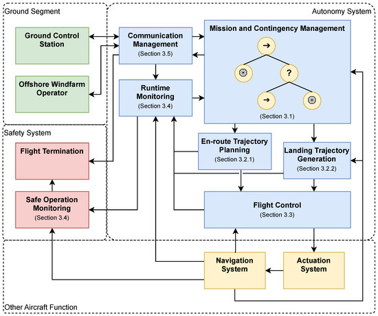
Figure 2.
Architectural decomposition of key functions and systems involved in the autonomous offshore wind park delivery mission.
The mission and contingency management (MCM) implements mission-specific procedures as well as high-level decision-making functionality. It exchanges information with the communication system, e.g., requesting and receiving clearances before crossing airspace boundaries. It receives highly aggregated information from a runtime-monitoring system to support decision-making regarding the mission and flight phase sequence. Furthermore, the information is used to trigger contingency procedures in case of certain events such as degraded flight performance, loss of link, failed landing attempts, or unexpected weather conditions. The MCM also triggers trajectory-planning algorithms specific to the current flight phase and manages the execution of planned trajectories. As a key technology for designing and implementing the decision-making functionality within the MCM, behavior trees are used. This is discussed in depth in Section 3.1.
The en-route trajectory planning computes flight routes from the onshore takeoff location to the wind farm and back. It takes into consideration the aircraft’s cruise airspeed, fuel reserves, wind forecast data and an offshore traffic network. En-route trajectories consist of 3D path segments with departure and arrival time annotations. Details on the sampling-based approach to solve this planning problem are given in Section 3.2.1. In contrast to this, a motion planner computes high-dimensional state space trajectories for the challenging task of landing and releasing cargo on WTGs. Landing trajectories are updated with high frequency throughout the landing procedure to guarantee a safe maneuvering in the vicinity of the WTGs. The approach for landing trajectory generation is detailed in Section 3.2.2. Algorithms involved in trajectory planning and optimization may not be real-time capable or may be difficult to prove in terms of reliable functioning, convergence, and runtime performance. In order to mitigate risks arising from the integration of such algorithms, information about individual planning procedures is passed to the runtime monitor where critical situations, e.g., exceeding computation times, are detected and passed on to the MCM. If required, contingency procedures may be triggered to mitigate any operational risks, e.g., by transitioning to hover and initiating the re-planning of the trajectory.
The flight control function enables the aircraft to fly along reference trajectories by calculating and sending actuator commands to the aircraft’s actuation system. It requires position, velocity, and attitude information from the navigation system at high frequencies. Also, it reports the current tracking performance, i.e., the error margin within which a given trajectory is tracked, to the runtime monitor. Details on the proposed design of the flight control system are given in Section 3.3. In our work, the navigation system is considered under basic aircraft functions as it is only considered to provide a reliable source of aircraft state information. If it is determined that additional sensors (e.g., for relative navigation) beyond the traditional integrated navigation solutions are required for the autonomy framework to function, one could also envision including the navigation system within the autonomy architecture.
The runtime monitor aggregates system and component state information into a Boolean verdict, on which the decision-making within the MCM is based. For example, it may monitor the tracking performance throughout the landing maneuver and decide whether the tracking errors are within the intended limits or not, which in turn may trigger the execution of a contingency maneuver. Additionally, it reports these signals to the safe operation monitoring system which is located within the safety system separated from the autonomy system. Like the runtime monitor, the safe operation monitor processes its input signals based on a specification; however, its output is a single Boolean signal used to activate a flight termination. Its purpose is to monitor the overall safety of the operation. If the aircraft is about to leave its specified flight volume or exceed other operating restrictions, the safe operation monitoring system triggers the safe termination of the flight to minimize any risks that would arise from continuing the flight outside the permissible operating limits. In Section 3.4, details on methods for designing and implementing runtime and safe operation monitoring are described.
The communication system manages the exchange of information via wireless data links with the Ground Control Station (GCS) but also with other communication partners such as the wind farm operator, and possibly with ships or other drones. More details on the communication system are given in Section 3.5.
Depending on the specifics of the operation, further functions may have to be integrated into the autonomy system that are not addressed in this work. For example, detect-and-avoid functionality may have to be added depending on the applied regulations and operational concept. Another example is sensor-based relative navigation for precision landings, which may be required when absolute navigation is not sufficient. Although the focus of this work is on the above-presented set of functions, the presented architecture follows a highly modular, layered approach, commonly referred to as a skill-based architecture in the robotics community; see, e.g., ref. [16]. With the MCM as the central entity for decision-making and execution scheduling, the integration of additional functions as new skills is straightforward.
3.1. Mission and Contingency Management
Nowadays, drones are usually able to automatically follow pre-planned, waypoint-based missions from takeoff to landing. They are even able to switch between a fixed set of alternate plans which are uploaded on the ground before takeoff. However, drones still lack the ability to react to unforeseen events or challenging situations independently of the remote pilot. Particularly, they are unable to perform robust strategic decision-making on when to continue, modify, or abandon a plan in favor of an alternate plan. Furthermore, this decision-making process has to be continuously performed in the context of ongoing lower-level actions, e.g., trajectory following or avoidance of obstacles. Consider, for example, the challenging maneuver of landing on an OWT. Even experienced human pilots would have to closely monitor the aircraft’s progress towards the landing, keeping in mind that a go-around may be required at any point during the maneuver if the aircraft is not stable enough. At the same time, the pilot monitors the fuel level to ensure that a go-around can still be safely performed and enough fuel remains for a new landing attempt. This kind of mission monitoring and decision-making is performed by the pilot during the plan execution phase, with all contingencies procedurally determined before the execution of the plan. The plan generation phase of decision-making, which happens before execution or upon interruption of the execution process due to an infeasible plan, is part of future work and not discussed in this paper. This work considers that there is no need for online mission plan generation and any contingencies are procedurally built into the plan execution framework.
In the context of the UDW project, some mission requirements need to be met by the onboard MCM. First, the MCM should be capable of following a set of robust procedures automatically. This ensures the safety of automated decision-making, as procedures can be specified and validated a priori by the designer. Second, the MCM should be capable of handling permissions from an external source, e.g., the OWF operator. This ensures safe operation of the drone within the wind park. Third, the MCM should be capable of handling denied permissions or system failures while retaining a high level of independence from the remote pilot for link-loss scenarios. Beyond these mission requirements, some architectural requirements also need to be considered. The MCM should implement a scalable yet easily interpretable plan execution framework for the designer and/or operator.
As a suitable formalism to model and implement the system’s behavior including the various phases of flight, decision points, and required actions, we propose the use of behavior trees. Originating from artificial intelligence programming in computer games, behavior trees have been well adopted by the robotics community and have been proposed in the past as a tool for autonomous unmanned aircraft [18,19]. With behavior trees, a system’s intended behavior can be decomposed into actions (leaf nodes of the tree), sequences of actions and alternate actions (so-called fallback nodes). Leaf nodes may have one of four states: inactive, running, success, and failure. At each time step, the tree is traversed from top to bottom and from left to right, activating nodes until a leaf node is found with state running. Additionally, decorator nodes are used to modify the returned state value of nodes or subtrees underneath. Below, to showcase the applicability of behavior trees to the scenario, we provide two examples of behavior trees that model different flight phases of the offshore wind park delivery mission.
Figure 3 shows a behavior tree to model the drone’s behavior during en-route flight. The behavior is simplified to illustrate the decision-making and action-scheduling capabilities. The root node is a reactive fallback node that restarts activating child nodes from left to right at each time step. This way, whenever there is a feasible trajectory (i.e., the condition <trajectory ok?> returns true), then the two parallel actions <update tracking command> and <analyze trajectory> are executed repeatedly unless one of them fails. Note that these actions may run asynchronously to the traversal of the behavior tree and the activation of nodes. If the current trajectory is judged to be <not ok>, e.g., there is a traffic conflict or a change in arrival time is expected due to the current wind conditions, then the en-route flight behavior will fall back to the <trajectory transition> behavior, which will make the drone follow along the current trajectory for a few seconds before entering into a loitering pattern. In parallel, the trajectory is re-planned until a new valid trajectory is available.
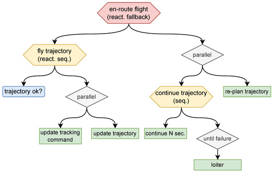
Figure 3.
Behavior tree for the en-route flight phase.
Figure 4 shows another example behavior tree for the landing maneuver. The drone is given a finite number of landing attempts. During each attempt, the reactive sequence <nominal landing> is executed first, which performs the landing while continuously monitoring the maneuver performance and checking whether the landing clearance is still ok. If any of these conditions fail, the <landing attempt> behavior falls back to execute a go-around, which will guide the drone back to a safe state from which the next landing attempt can be initiated.
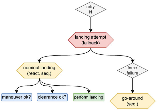
Figure 4.
Behavior tree for the landing maneuver.
The offshore wind farm delivery mission is characterized by its flight phases, decision points that are known a priori, e.g., entering the wind farm, during landing attempts, and the need to possibly re-plan the trajectory within certain operational constraints. The examples shown above demonstrate the expressiveness and composability of behavior trees and give an indication of the applicability of behavior trees as a tool for modeling and implementing autonomous behavior in this scenario. To make the modeled behavior executable, implementations for the leaf nodes of the behavior tree must be provided that interface with onboard capabilities, also referred to as skills in a skill-based architecture [20]. The following sections provide details on trajectory planning, flight control, and communication management, which form the functional layer on which an essential set of skills for the addressed scenario can be implemented.
3.2. Trajectory Planning
In the following, we present algorithmic solutions for two distinct trajectory-planning tasks in the context of the offshore drone logistics scenario: planning trajectories for the en-route flight phase and for the autonomous landing maneuver.
3.2.1. En-Route Trajectory Planning
Flight path-planning algorithms enable autonomous drones to anticipate and control their flight movements in the future. For en-route flight to and from the OWF, coarsely planned 3D flight corridors are sufficient to estimate time-of-arrival and to check whether the flight path is clear of traffic obstacles. The en-route planning scenario, depicted in Figure 5, is characterized by a set of specific requirements:
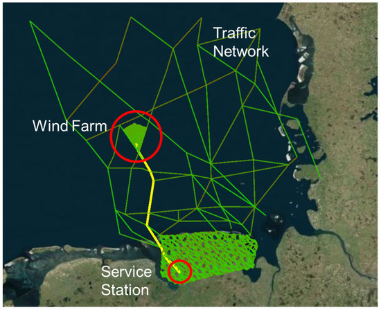
Figure 5.
En-route trajectory-planning scenario from the onshore service station to the OWF with the search graph (green) and planned trajectory (yellow) [21].
- Flying over the North Sea to and from the OWF, the drone should follow traffic patterns and existing routes used by manned helicopter operations to simplify the airspace management and avoid potential conflicts.
- Arrival time windows must be planned ahead to coincide with deployment of personnel in order to minimize shutdown times of individual WTGs. Consequently, flight time and arrival time estimates should be accurate to the minute considering wind forecast data.
- As servicing and refueling the drone at the OWF should not be part of the nominal operation, sufficient fuel reserves for the return flight must be accounted for.
- Re-planning should be possible within a few seconds with onboard computers, enabling the drone to react autonomously to incoming traffic information, changes in wind, or other unexpected events.
An algorithmic framework aiming to satisfy these constraints was developed in the UDW project [21]. It is based on the authors’ line of work regarding the application of the Probabilistic Roadmap Method (PRM) and its derivatives [22,23] for runtime-efficient onboard path and trajectory planning for autonomous drones. The key concept of PRM is a heavily pre-processed cyclic search graph, which allows the inclusion of all prior knowledge about the scenario in a form accessible to runtime-efficient graph search algorithms. Hence, it is well suited for online planning in mostly static and pre-determined scenarios where runtime is critical and sufficient a priori knowledge is available. Given the offshore logistics scenario with its above-mentioned requirements, PRM is a suitable approach for planning en-route trajectories. In previous work, it has been shown that PRM is a suitable approach for online re-planning of the flight path of unmanned helicopters [24], and for planning trajectories that account for the prevailing wind [25]. More recently, the approach has been modified to account for time-varying cost functions [26]. This represents a key ingredient to account for wind forecast data, i.e., wind fields varying over space and time. Below is a brief summary of the approach for the en-route trajectory planning proposed in [21].
Whereas with PRM, the search graph is typically constructed via quasi-random sampling, the offshore traffic network is used as the basis for the search graph here. It is, however, extended by quasi-randomly sampled regions to extend the search graph towards the onshore service station and into the offshore wind farm. Flight time is used as the cost function to be minimized which—assuming that the en-route segment is flown at constant cruise airspeed—also serves as an indicator for fuel consumption.
Given a wind field from a weather forecast model, the flight time along each edge of the search graph is computed throughout the time window targeted for the flight at a limited resolution, e.g., every 10 min. The resulting search graph can be queried for optimal trajectories with a slightly modified A* search graph algorithm that accounts for the flight time when querying edge cost as described in [26].
In order to adhere to pre-planned arrival time windows and to consider the return flight as well, each planning procedure consists of two graph search runs: the trajectory to the OWF is planned backwards from the OWF and from the fixed arrival time to the takeoff location, whereas the return flight is planned forward from the OWF and from a point in time shortly after the scheduled arrival time.
Benchmark results, as presented in [21], indicate good runtime efficiency with typical runtimes of approximately ten seconds. Considering the coarse nature of the planned trajectories, this runtime is sufficient to react to changes in weather forecast data, target WTGs or allowed traffic network paths. To further decrease runtimes, the search graph size could be limited by reducing the size and sampling resolution within the quasi-randomly sampled regions. Hence, this algorithmic approach provides a suitable solution for the planning and online re-planning of en-route trajectories in the offshore logistics scenario. For the en-route flight phase, coarsely planned 3D flight corridors with airspeed, ground speed, and flight time estimations suffice. To perform precision landings on WTGs, more fine-grained motion planning is required, taking into account the aircraft dynamics, as described in the next section.
3.2.2. Motion Planning for Safe Landing
The ability to safely land is a vital skill when operating in remote offshore environments. Apart from enabling the drone to unload cargo on wind turbines or other offshore infrastructure, the ability to land also opens the possibility to refuel and to perform emergency landings on unprepared sites or ships, thus avoiding the loss of the drone and cargo. In contrast to en-route trajectory planning, a landing maneuver requires a trajectory which considers the system dynamics in order to control the flight motion precisely. In order to ensure that the drone safely reaches the landing pad, constraints on position, velocity, and attitude must be enforced during the whole maneuver. We therefore need a method for trajectory planning that optimizes over full-state trajectories. Furthermore, high wind speeds and turbulence induce uncertainty into the system, making robustness a key requirement of the landing algorithm. To tackle these problems, we employ a particular kind of MPC with robustness guarantees in the face of external disturbances.
MPC is a versatile tool that is predominantly used to control systems with state and input constraints. By predicting the trajectory of the system over a given finite time horizon, an input trajectory is optimized online such that the constraints of the system are met during this prediction horizon. This is carried out at every time step, i.e., an input trajectory with a given prediction horizon is computed from the currently measured state and only the first input is applied to the system. Usually, the performance and stability of the MPC depend on the length of the prediction horizon and are difficult to prove in many cases. However, specialized formulations exist [27] that ensure the stability of the controller by enforcing the last state in the prediction horizon to lie in a given region called the terminal set. The main drawback of this method is that this terminal set must contain an equilibrium of the system, e.g., a hover for VTOL UAVs. However, we must be at a specific region with a certain downward velocity at the end of the landing maneuver to ensure a safe touchdown, which is unfortunately not an equilibrium.
In this work, we therefore integrate the MPC formulation proposed in [28] which utilizes shrinking prediction horizons, i.e., the horizon length is decreased at every time step. This approach guarantees the safe completion of the maneuver in finite time without any equilibria in the target set, which is not the case for constant horizon formulations such as [29]. In other words, planned trajectories must not necessarily end in a hover, but can instead include non-stationary states like a descent with a specified velocity. This allows for more dynamic landing maneuvers, reducing time-to-land and thus fuel consumption while also providing constraint satisfaction guarantees until touchdown. While this is also possible using polynomial trajectory generation methods [30], they lack robustness guarantees and require iterative refinement of segment times and intermediate waypoints to satisfy dynamic constraints. The proposed approach in [28] however utilizes a tube-based MPC formulation that can provide these guarantees even in the presence of uncertain-but-bounded disturbances acting on the UAV [29], thus mitigating the influence of turbulent winds. This is achieved by employing an auxiliary controller that keeps the true system in the vicinity of a nominal trajectory generated by the MPC. In this work, the outer-loop controller in Section 3.3 doubles as the auxiliary controller. In contrast to the robust variable horizon strategy proposed in [31], the shrinking horizon MPC problem can be cast as a quadratic program, thus lending itself to efficient off-the-shelf solvers which also support embedded application. In our desktop experiments, we achieved average computation times of approximately five milliseconds for a horizon of 300 steps and ten decision inputs without any code optimization (see [28] for details). Considering a sampling time of 20 ms for the outer-loop controller, this runtime would suffice for real-time usage.
The model used for trajectory planning consists of three separate 3rd-order integrator chains representing the position, velocity, and acceleration in the heading-fixed x, y, and z directions, which are defined to align with the North–East–Down frame for a yaw angle of zero. Several UAV configurations may be translated into such a model structure, such as multicopters [32], helicopters [33], and other VTOL UAVs [34]. In this work, we consider a helicopter which is transformed into integrator form by pre-stabilizing the attitude states and feedback-linearizing the translational dynamics as in [33].
The MPC algorithm requires certain conditions to be met before it can be properly executed. In the following, we describe its integration into the autonomy architecture as well as its interaction with the MCM and the runtime-monitoring system.
For the successful execution of the algorithm, the landing target must be reachable within the prediction horizon of the MPC. It follows that the allowable distance from the landing target in which the MPC can be activated depends on the prediction horizon length. Although the approach in [28] is designed to deal with very long prediction horizons, planning trajectories with more than ten seconds of prediction time are likely not realizable on current onboard hardware setups. Therefore, there exists a region around the landing target within which the MPC can be engaged. Using optimization, it is possible to obtain a target waypoint within this region to which the en-route planner may connect as its last node. Thus, the en-route planner leads the UAV towards a suitable starting point for the MPC to take over, ensuring a seamless switch between the trajectory-planning modules. Additionally, before engaging the landing, the heading of the UAV must point in the general direction of the landing target. Therefore, the generated waypoint also defines the target heading. If all conditions for the execution of the landing algorithm are met, a flag is sent to the runtime monitor to signal its availability. After the maneuver is then initiated by the MCM, the landing trajectory is continuously re-planned at a given frequency in order to better compensate for deviations from the planned trajectory and to obtain better optimization results the closer the target gets. For more details, we refer to the section on move blocking in [28].
Even though the MPC algorithm provides theoretical guarantees, it requires assumptions about the disturbance bounds during operation. To monitor if these assumptions hold, a disturbance observer can additionally be deployed to report estimated disturbances during operation to the runtime-monitoring system. Another indicator that the true system violates assumptions made during the design is trajectory-tracking performance. Therefore, the UAV’s deviation from the nominal trajectory is also monitored. If the monitor detects one of these violations, the theoretical guarantees of the MPC will no longer hold. However, this does not necessarily mean that the optimization fails and a safe landing is impossible. Thus, in this case, a warning flag is sent to the runtime monitor as it might be possible to recover from a temporary violation. When the execution of the MPC is resumed despite the warning and the optimization becomes infeasible, an error flag is sent to the runtime monitor. The MCM must then decide whether to force the landing via the previously planned trajectory or abort the landing attempt by initiating a go-round.
With this approach to planning landing maneuvers and the en-route trajectory planning from Section 3.2.1, suitable motion-planning methods are available to meet the requirements of all flight phases in the offshore logistics scenario. To actually execute the en-route trajectories and landing maneuvers, a flight control system is required, as described in the next section.
3.3. Flight Control
The role of the flight controller is to enable the UAV to fly along reference trajectories that have been planned for specific flight phases, rejecting any external disturbances and handling the vehicle’s inherent flight dynamics. For this study, we consider a helicopter configuration. The controller architecture which resembles an inner–outer-loop structure is shown in Figure 6. The outer-loop controller is responsible for tracking a desired trajectory characterized by a local North–East–Down (NED) reference position and velocity as well as a feedforward acceleration . Depending on the currently active trajectory-planning mode, these references are either provided by the landing planner (see Section 3.2.2) or generated by a command filter from velocity and yaw rate setpoints provided by the en-route planner (see Section 3.2.1). The inner-loop controller tracks the pitch , roll , and yaw rate commands generated by the outer-loop controller. Additionally, the outer controller provides a feedforward acceleration to control the heave motion of the helicopter. The inner-loop controller sends longitudinal and lateral cyclic, pedal, and collective inputs (, , , and ) to the servo motors. In the following, each part of the controller architecture is described in more detail.
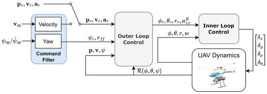
Figure 6.
Helicopter control architecture, composed of an inner-loop controller for attitude tracking, an outer-loop controller, and a command filter to smooth out setpoint changes.
3.3.1. Outer-Loop Control
During landing, the outer-loop controller must be able to track trajectories generated by the MPC. The reference passed to the outer controller is thus given by the state vector of the MPC model, i.e., references for NED position , velocity , and acceleration , which is also going to be passed as a reference to the outer-loop controller. Additionally, a yaw reference is provided. In order to track these references, we consider the outer-loop model proposed by [33]:
where is the rotation matrix, g is the gravitational acceleration, and is the body-fixed acceleration reference which is controlled using the collective input . Finally, is the desired yaw rate. This outer-loop model is a common starting point for most helicopter control approaches found in the literature. In [35], Isidori et al. designed nested saturated outer feedback laws the synchronization with the sinusoidal heaving motion of a ship. Fixed-time sliding mode laws are employed in [36] to achieve fast convergence while guaranteeing robustness to external disturbances. In [37], robustness is achieved using Incremental Nonlinear Dynamic Inversion, a sensor-based approach where acceleration measurements from an inertial measurement unit are used to compensate uncertainties and disturbances. In this work, however, we employ a rather simple control scheme where a nonlinear flatness-based transformation is used to relate a desired acceleration to the reference commands , , and . The yaw angle can then be controlled independently to track a reference yaw angle as the desired acceleration does not specify the orientation of the UAV. For more details, we refer to [33]. This approach allows us to design linear controllers acting on the acceleration and yaw rate, which are easy to implement and lend themselves to optimization-based tuning (see Section 3.3.3). This is in contrast to the previously mentioned approaches where proper tuning is non-trivial and can be fairly risky when conducting flight tests. Furthermore, a simple controller structure greatly simplifies the construction of the tubes [38] needed for the proposed robust MPC approach. Thus, we employ linear controllers for and . We design a Proportional–Integral–Derivative controller for and a Proportional controller acting on the polar error for , both with feedforward terms and , respectively. Specifically, we choose
where , , and represent the gain matrices for position error, velocity error, and velocity error integral, respectively, and is the yaw error gain.
3.3.2. Command Filter
For the outer-loop controller design, we assume that a full-state reference with feedforward commands is available. In the case of no disturbances, the feedforward acceleration would ensure that the helicopter follows the desired position and velocity exactly. Thus, the feedback terms are only active if there are deviations from the assumed model. Therefore, the corresponding gains are mainly tuned for disturbance rejection performance, as only small deviations from the reference position and velocity are expected. The en-route planner however provides velocity and yaw rate setpoints to the controller, which are not dynamically consistent with the outer-loop model in Equation (1). This may lead to much higher velocity errors than in the trajectory control case, causing an aggressive response from the controller. In order to decouple the response to setpoint jumps from the disturbance rejection response, a command filter is employed to smooth out the desired velocity given to the controller and provide it with the necessary feedforward acceleration, ensuring dynamically feasible references. Furthermore, the command filters ensure that given acceleration and yaw rate bounds are satisfied.
This approach offers helpful advantages: First, the controller structure remains the same for both path following and trajectory tracking, so only one set of controller gains is required. Second, we assure dynamically accurate and therefore seamless transitions between path-following and trajectory-tracking mode by seeding the command filters or trajectory planners with the current reference position and velocity.
3.3.3. Inner-Loop Control
Autonomous aircraft must operate with precision, reliability, and safety. Therefore, clear, measurable, and verifiable requirements on the flight control system have to be formulated. Aerospace specifications such as MIL-STD-1797, ARP94900, and ARP94910 define recommended practices and industrial standards that are considered safe and suitable for the design, installation, and test of flight control systems [39,40,41]. In this context, a general overview of the most important criteria within a requirement-based flight controller design is given by Table A1 in Appendix A. Among these criteria, it is most important to guarantee that the required stability margins are achieved while still providing a sufficient tracking performance and decoupling of the different control channels. This typically leads to a trade-off between robustness and performance in the controller design.
To meet the desired requirements, different kinds of control design methods can be applied. Most widely used in the context of flight control are for example eigenstructure assignment [42], model reference adaptive control (MRAC) [43], loop shaping [44], control [45], and synthesis [46]. Eigenstructure assignment allows us to shape the response behavior as well as coupling effects in the time domain by a suitable choice of eigenvalues and eigenvectors. However, this method requires full-state feedback, which is problematic for helicopter UAVs since flapping angle measurements are usually not available. For systems with uncertain parameters, adaptive control such as MRAC can be applied to achieve desired closed-loop behavior. However, the method’s robustness highly depends on the tuning of the adaptation gains and full-state feedback is required as well. Frequency-based methods such as loop shaping and control allow us to directly consider important characteristics like gain and phase margins as well as controller bandwidth. While loop shaping is hard to tune, the control problem can be formulated as an optimization problem, making it very attractive to achieve multiple design criteria. Within the -based optimization, disturbance signals and wind can be defined, enhancing the performance of the controller under uncertain conditions. In addition, loop shaping and can be applied to tune given controller structures such as simple Proportional–Integral–Derivative (PID) controllers, enabling output feedback and therefore avoiding the design of additional observers. As an extension of methods, synthesis allows us to explicitly model uncertainties and to design controllers that are especially robust with guaranteed robust performance and robust stability.
The inner-loop controller design for the helicopter used in this work is illustrated in Figure 7. A approach with multiple design goals is applied to achieve the desired performance and robustness criteria. We apply single-axis control for the channels of pitch , roll , yaw rate r, and heave velocity w. This reduces the number of optimization parameters and simplifies the manual adjustment of controller parameters in flight experiments. For each axis, a PID feedback controller with a feedforward term is applied. To avoid oscillations in the pitch and roll channel, we apply additional damping by feedback of the roll and pitch rates. Finally, we apply phase-lead and phase-lag elements to achieve the desired robustness. Depending on the specific dynamics of the helicopter UAV, it might also be necessary to add notch filters [47] to avoid feedback loop excitation of rotor-induced vibrations. Details on the controller design can also be found in [48].
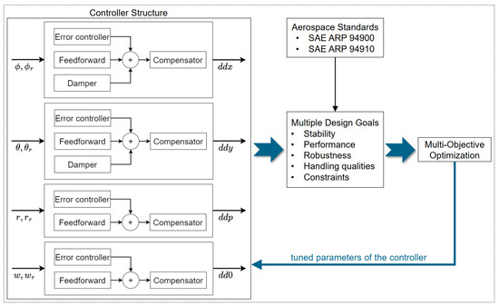
Figure 7.
Helicopter controller tuning based on multi-objective optimization.
3.4. Runtime Monitoring
Technical solutions to realize onboard capabilities for autonomy always rely on a set of assumptions about the system itself or its operating environment. Consider, for example, the intensity of wind disturbances and resulting flight control performance when landing on a WTG. Also, there may be performance requirements of individual functions that cannot be verified a priori, such as runtimes of complex planning algorithms. Finally, hardware or software failures can cause individual components to malfunction and affect the overall behavior of the system. Runtime monitoring involves building monitors that detect misbehavior of individual functions or at the system level during operation, i.e., in flight. The concept of runtime monitoring is relevant in the context of runtime assurance architectures, where a complex function which may not be developed to the required assurance standards is secured by a safety net of runtime monitors and recovery functions. The runtime assurance architecture paradigm has been formalized by the American Society for Testing and Materials (ASTM) International in the standard practice ASTM F3269-21 [49]. A more detailed discussion of the standard practice, its impact on certification aspects, and application to assure the safety of operations for highly automated cargo delivery drones is available in [50]. Hence, runtime monitoring is a key technology to make autonomous systems more robust and resilient against technical failures and adverse operating conditions.
In [51], we introduced a hierarchy of monitoring properties for autonomous systems. This hierarchy includes five levels, listed in ascending order of abstraction: item level, system level, aircraft level, mission level, and operation level. The requirements of the flight controller are examples of item-level and system-level requirements. Another example is the monitoring of disturbance assumptions introduced by the landing MPC approach in Section 3.2.2. An example of an aircraft-level requirement is that when an altitude increase is commanded, it must be observed within three seconds. While these levels are widely applicable to many cyber–physical systems, the mission level and operation level are particularly important for autonomous systems. The mission-level requirements ensure that the planned mission is executed as expected. At the operation level, requirements ensure that the executed mission remains within its defined operational limits. For instance, these include flight rules and the temporal progress and deviation of the planned trajectory. In this context, the European Union Aviation Safety Agency (EASA) recently introduced the concept of the Operational Design Domain (ODD) and Out-of-Distribution (OOD). The idea of the ODD is to define “Operating conditions under which a given Machine Learning (ML) constituent is specifically designed to function as intended” [52]. These concepts were introduced in the context of ML; however, they can be utilized in the same way in the context of autonomy to define “Operating conditions under which a given autonomy function is specifically designed to function as intended”. The definition and characterization of the ODD is still an ongoing research process; a data-centric approach and data design for ODD were recently shown [53,54]. By monitoring such conditions, it can be assured that the ML constituent or the autonomous functions are correctly operated in the assumed conditions [55]. In the context of the UDW mission, additional requirements at this level include wind, weather, time of day, and spatial operational constraints known as geofences. These concepts are aggregated under the umbrella term of Safe Operation Monitoring, as characterized initially by Torens et al. in [56] for a geofencing monitor and later from an algorithmic perspective by Schirmer et al. in [57].
Our monitors serve two functions: first, providing feedback to the MCM and second, initiating flight termination when necessary. Both monitors are depicted in Figure 2, where runtime monitoring implements the first function, while safe operation monitoring is responsible for the second. The safe operation monitor is critical to ensuring overall safety and, as such, represents the key safety-critical function. To maintain independence from the autonomic system, the safe operation monitor and the flight termination system run on dedicated hardware. It should be noted here that the actual safety criticality and independence/redundancy requirements of the runtime monitor and the safe operation monitor would need to be determined for each use case separately considering the actual risk of the operation and the corresponding regulatory framework. With respect to their software implementation, we investigate the use of monitoring specification languages. These languages offer dedicated operators that simplify specifying more complex properties that arise from autonomous systems compared to handwritten code. After the specification is written, a corresponding monitor is automatically generated that checks for violations. For example, the requirement—after receiving a command (cmd) for takeoff, the aircraft must reach an altitude of 600 feet within 40 s—is expressed concisely by
Here, the operator □ denotes that a property must always hold, while ◊ states that a property must eventually hold. In this example, ◊ is bounded to eventually hold within 40 s, while □ is unbounded and must therefore hold during the whole flight. In [51], various specification languages are compared, while [58] introduces the specification language Temporal Behavior Trees. This language retrofits specifications to behavior trees, such as those shown in Figure 3 and Figure 4. An introduction to this field of research is given in [59].
3.5. Connectivity and Communication Management
Connectivity is a key ability for autonomous offshore drone operations as information must be exchanged between multiple stakeholders: the drone itself, the Ground Control Station, the wind farm operator, and other sea and air traffic participants. Hence, onboard communication management provides an interface to multiple communication channels and manages the corresponding information flows. The need for information exchange and possible technical solutions are discussed in detail below.
The procedure for an autonomous drone to enter the airspace of an offshore wind farm and prepare to land on a WTG, as shown in Figure 1, is a prime example of the connectivity requirements. Specifically, the autonomous drone, as an asset for which the drone operator is responsible, must exchange information with the offshore wind farm operator and the wind turbine. The wind farm is a restricted air space, as it is an energy production infrastructure. Entering this air space requires approval from the wind farm operator (Art 3 3. §21h LuftVO [60] in conjunction with EU regulation 2019/947 [61]). Since the wind farm operator has an overview of other ongoing and planned activities within the wind farm, the operator can determine if shutting the wind turbine down for delivery is possible and reasonable. By approving entry, the wind farm operator also communicates their intention to stop the anticipated wind turbine in our example. On the other hand, the wind turbine provides valuable, up-to-date information required for a safe landing, such as the status of the wind turbine, including a ready-to-land signal to the drone and the orientation of its nacelle, as well as the current measured wind speed.
We distinguish two abilities that an autonomous drone needs in our context. First, the drone needs connectivity as a technical ability to communicate with the offshore wind farm operator, wind turbine, and the GCS. Second, the drone needs the ability to process incoming and outgoing information as an interface to other autonomous functions. These abilities are implemented by the communication management (CoM) system. Information processing tasks vary in complexity. Converting an external to an internal data format is a simple task if the formats are easily processable like variables encoded in JavaScript Object Notation (JSON). However, converting, processing, and interpreting received data to abstract information like a “flight approval” are of higher complexity. External to internal is a translation between data formats and their encoding established by different participant groups. The communication medium and data producer can strongly influence external data formats. In contrast, developers of autonomous abilities, and hence data consumers, influence internal data formats. Both groups can differ in their interests. Furthermore, CoM creates information by processing and interpreting numerous received data pieces. Hereby, it allows other system capabilities to function on a more abstract level of data. In our context, CoM handles “flight approval” and “landing clearance” as essential information, which are primarily used by the MCM. Flight approval includes the permission to enter the wind farm and the wind farm operator’s promise to stop the target wind turbine. Landing clearance indicates that the wind turbine is prepared for a safe landing.
Figure 8 outlines the delivery process and the CoM’s tasks. Before entering the wind farm as depicted in Figure 8a, the autonomous drone must obtain approval. CoM receives information on the target wind turbine from the MCM. Now, CoM formulates and sends a specific approval request to the wind farm operator. Once it receives the approval, CoM delegates it to the MCM, and the delivery mission can progress to Figure 8b. Meanwhile, CoM holds the approval information active and constantly checks for a change. Furthermore, it automatically aggregates data pieces to essential information on landing clearance. The landing clearance indicates a landing is safely possible based on communicated data from the wind turbine, i.e., the wind turbine is ready and prepared for the landing. For that, the turbine’s rotor speed must be below a threshold to indicate a positive landing clearance to the MCM, as depicted in Figure 8c. Depending on the landing procedure, the nacelle’s position may have to be perpendicular to the current wind direction. This is considered a safe position also used for manned helicopter landings as it allows for landing attempts to be aborted by flying into the wind, quickly gaining altitude. This is also referred to as the hoist mode of the turbine. The turbine’s status, including rotor speed, the nacelle’s orientation, and hoist mode status, is received and processed by the CoM. Additionally, CoM collects data such as the current wind speed, which serve as inputs to other autonomy functions. Once the drone has finished its delivery and exits the wind farm, CoM formulates another request to the wind farm operator to end the approval, signaling that the turbine can start again, cf. Figure 8d.
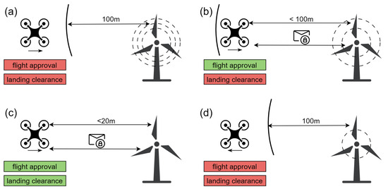
Figure 8.
Delivery process towards the wind turbine with essential information provided to the MCM by CoM in four stages (a–d). On approach in (a), no approval exists, and a distance of more than 100 m has to be maintained. In (b), approval exists, which results in communication with the turbine and the stopping of the rotors. A positive landing clearance in (c) indicates that the turbine has stopped and is ready for the approach. Communication is maintained until the delivery is finished, and CoM ends the flight approval once it leaves the authorization area in (d).
We implemented an instantiation of our described communication management in an experimental setup and validated it in an onshore flight test. All data were shared in a JSON text format over a Message Queuing Telemetry Transport (MQTT) broker. For example, the approval request was formulated as a textual status field and could be accepted or denied with a dialog button press on the wind farm operator side. Donkels et al. [1] provide experimental details of an onshore flight test with the unmanned helicopter superARTIS, which is operated by DLR as a research testbed and has an approximate maximum takeoff mass of 90 kg.
4. Discussion
In this section, we discuss our choice of technologies, architecture pattern, the development and integration status of the different functions in the autonomy framework, the use of this architecture in a safety-critical context, and finally the scope of the planned future work.
4.1. Assessment of Technological Choices
It is to be noted that the complete functional chain of the proposed autonomy framework is yet to be demonstrated. However, individual technologies presented in this work seem suitable as tools to solve the respective tasks. Behavior trees provide a rich and composable formalism to model autonomous behavior and decision-making. Given that the overall course of the offshore cargo mission is pre-determined with fixed decision points and strict procedures, we believe the onboard mission and contingency management could be modeled within a single behavior tree without the need for further task-level planning and decision-making algorithms. This approach may have to be revisited for more complex mission scenarios. Regarding trajectory planning, the need to use different algorithmic approaches for different phases of the flight has become evident. In this work, we propose a graph-based algorithm for the en-route flight phase and an MPC-based approach for the landing maneuver. We show that flight control design can be realized with well-established and understood methods. However, it is important to note that a robust controller performance is the foundation for safe autonomous flight and therefore must be thoroughly designed according to state-of-the-art principles. Connectivity is more of an infrastructural challenge than a technical one to solve from an onboard perspective. However, a good integration of the cargo drone with the offshore logistics system requires clearly defined procedures and a tight integration with the onboard decision-making. Finally, runtime monitoring can enhance the robustness and safety of the autonomous operation, and potentially reduce the effort required for the verification of complex onboard functions.
4.2. Discussion of the Autonomy System Architecture
The use of behavior trees for mission management allows us to move away from traditional hierarchical finite-state machines. Also, the use of behavior trees lends itself to integration in skill-based architectures as commonly used in robotics to aggregate and separate functional capabilities in a hierarchical manner across different layers. The use of a skill-based tiered architecture allows us to separate the different functions at a layer level, e.g., a deliberative layer for mission management (see Section 3.1), executive layer for skill management, and functional layer for basic autopilot. Skill management, in the context of this work, refers to the management of advanced skills such as en-route trajectory planning (see Section 3.2.1), safe landing planning (see Section 3.2.2), and advanced flight control functions (see Section 3.3). The interfaces between these functions can be managed in a modular manner across the layers and within the layer, allowing for independent development and testing while being capable of integration in the autonomy framework. The capabilities of runtime monitoring (see Section 3.4) and communication management (see Section 3.5) are currently not strictly allocated to a specific layer within the architectural framework. Communication management has a significant influence on the decision-making capabilities and therefore is likely to be allocated to the deliberation layer, as a primary input to MCM. As described briefly in Section 3.4, the capability consists of multiple hierarchically ordered monitors at the item, system, aircraft, mission, and operation levels. Therefore, the allocation of these monitors will be made in accordance with the appropriate abstraction level in the three architectural layers. For example, the operation-level monitor could be allocated to the deliberation layer due to its impact on mission management, while the system-level monitor could be allocated to the executive (skill) layer as part of a modular system reconfiguration capability.
4.3. Discussion of Safety and Assurance Aspects
The use case presented in this work is safety-critical in the sense of the expected high operational risk. This risk arises from the criticality of the infrastructure around which the drone needs to operate, the ecological impact of a potential crash in the sea, as well as ground and air risk to other participants in the maritime environment (e.g., manned helicopters, shipping operations). These risks require the drone to be robust against system or sensor failures as well as the harsh environmental conditions (e.g., salt spray, humidity and precipitation, strong winds). This work partially addresses one of these aspects, i.e., the robustness of the flight controller to disturbances (see Section 3.2.2 and Section 3.3). The runtime-monitoring approach described in Section 3.4 also indicates how system or sensor failures as well as anomalies in flight behavior could be detected in a timely manner. However, a discussion on the robustness of the airframe and avionics against the other environmental conditions is not in the scope of our work. Moreover, while we showcase the suitability of behavior trees for mission and contingency management, we do not show how the actual planning algorithms behind it work or how the system deals with system failures or other unforeseen circumstances during the operation. This will be published in future work on the mission and contingency management system, with this work merely posing behavior trees as a suitable tool for housing this functionality. The en-route trajectory planner described in Section 3.2 can consider ground risk constraints as well as temporal and spatial air risk constraints, which addresses further aspects of safe operations. However, while our autonomy framework and architecture consider safety through the provision of certain capabilities to deal with the operational environment, our work does not address architectural or system safety concerns. To do so would exceed the scope of this paper by a wide margin. Furthermore, the regulatory guidance in this regard is still evolving and means of compliance to applicable regulation [61] are still being developed by industry and the certification authorities. We therefore do not make any claims of safety on behalf of the architecture itself. We discuss certification aspects specific to the topic of runtime monitoring in Section 3.4. However, here, we refer to prior work [50] as well as an industry consensus standard [49] for a more detailed review of these aspects and, in particular, on the architectural allocation of safety and development assurance targets for the constituent systems in such an architecture.
4.4. Current State of Integration and Future Work
In this work, we showcased the overall framework and the constituent modules at varying levels of detail. At the time of this publication, we are working towards the integrated testing of all the modules together. Preliminary interfaces have been defined for the en-route trajectory planner and the safe landing planner. An integrated testing of the two modules has also been carried out in simulation for a nominal case, i.e., en-route trajectory planning, flight along the planned trajectory, transition to the safe landing planner, and a safe autonomous landing on the simulated WTG. The next step is to refine the interfaces between the mission management module and the trajectory planners. Preliminary interfaces for the mission management module to request a constraint-satisfying trajectory between two waypoints from the en-route trajectory planner are well understood and a fast-time simulation is being developed to test this interface. In future work, we plan to test in simulation and flight testing, with the integration of all the modules for a representative use case such as the one depicted in Figure 1. A typical validation process would include the definition of a benchmarking scenario with distinct test cases.
5. Conclusions
In this paper, we have presented an autonomy architecture and framework for automating the delivery of goods in offshore wind parks using UAVs. We detailed its key components: a mission and contingency management that coordinates the mission and follows contingency procedures in response to safety risks; the en-route and landing trajectory planners that generate trajectories executed by the flight controller for the respective task; runtime monitors that check the correct and safe conduct of flight; and a dedicated communication management system that ensures the seamless coordination with the OWF operator and the offshore cargo logistics services. Finally, we discussed the steps toward integration and flight tests as well as future work towards the deployment of autonomous unmanned aircraft in offshore wind farms.
Author Contributions
The contributions of each author are listed per section for easier readability. Each author of this paper contributed to conceptualization/methodology/software/writing—original draft preparation, as applicable for their individual sections as follows—A.D. for Section 1 and Section 2, P.N. for Section 3.1 with support from S.S. (Simon Schopferer), S.S. (Simon Schopferer) for Section 3.2.1, P.S. for Section 3.2.2, M.S. for Section 3.3, S.S. (Sebastian Schirmer) and C.T. for Section 3.4, and F.K. for Section 3.5. All aforementioned authors contributed to writing—review and editing of the paper. J.C.D. contributed to supervision of P.N. and P.S., and supported methodology discussions for Section 3.1 and Section 3.2.2, the framing of the offshore drone delivery use case as well as project administration for the UDW project. S.C. (DLR) and V.S. (EnBW) led the project administration and funding acquisition activities as well as enabled the research activities of the co-authors by framing an industry-relevant use case for the offshore drone delivery mission as discussed in Section 1 and Section 2. All authors have read and agreed to the published version of the manuscript.
Funding
This research was funded by the Federal Ministry for Economics Affairs and Climate Action (BMWK) under grant number 03EE3059B.
Data Availability Statement
The original contributions presented in this study are included in the article. Further inquiries can be directed to the corresponding author.
Acknowledgments
We acknowledge the support of the UDW project teams at DLR and EnBW as well as associated partners. We thank the technical staff at the Department of Unmanned Aircraft at the DLR Institute of Flight Systems for their support in flight testing activities. We are grateful for the feedback from the offshore wind energy and cargo drone delivery communities as well as stakeholders from the German federal government as part of the Offshore Drone Challenge in June 2024 and the UDW Symposium in January 2025. We thank Bojan Lukic from the Department of Safe Systems and Systems Engineering at the DLR Institute of Flight Systems for the review of the manuscript. The icons used in Figure 8 were licensed by kawalanicon, kosonicon and amoghdesign from flaticon.
Conflicts of Interest
Author Vincenz Schneider is employed by the company EnBW Energie Baden-Württemberg AG. The remaining authors declare that the research was conducted in the absence of any commercial or financial relationships that could be construed as a potential conflict of interest.
Abbreviations
The following abbreviations are used in this manuscript:
| AACUS | Autonomous Aerial Cargo Utility System |
| ALIAS | Aircrew Labor In-cockpit Automation System |
| ASTM | American Society for Testing and Materials |
| CoM | Communication management |
| DARPA | Defense Advanced Research Projects Agency |
| EASA | European Union Aviation Safety Agency |
| EEZ | Exclusive Economic Zone |
| GCS | Ground Control Station |
| GNSS | Global Navigation Satellite System |
| ICAO | International Civil Aviation Organization |
| JSON | JavaScript Object Notation |
| MCM | Mission and contingency management |
| ML | Machine learning |
| MPC | Model Predictive Control |
| MQTT | Message Queuing Telemetry Transport |
| ONR | Office of Naval Research |
| OWF | Offshore wind farm |
| OWT | Offshore Wind Turbine |
| PRM | Probabilistic Roadmap Method |
| TALOS | Tactical Autonomous Aerial LOgistics System |
| UAS | Unmanned Aircraft System |
| UAV | Unmanned Aerial Vehicle |
| UDW | Upcoming Drones Windfarm |
| VTOL | Vertical Takeoff and Landing |
| WTG | Wind Turbine Generator |
Appendix A
The following table specifies the most important criteria within a requirement-based flight controller design. For further details see also [39,40,41].

Table A1.
Requirements in flight control design.
Table A1.
Requirements in flight control design.
| Response behavior | Response characteristic defined by rise time, settling time, and damping. |
| Tracking performance | Limited stationary control errors under calm and turbulent air as well as under model uncertainty. |
| Decoupling | Sufficient mitigation of cross-coupling effects. |
| Stability and robustness | Robustness analysis using e.g., structured singular value, gain and phase margins, and/or disk margins. |
| Sensitivity | Sufficient but limited control bandwidth to limit sensitivity wrt. system parameters and disturbances. |
| Input constraints | Handling of actuator limitations and limited accelerations. |
| Signal limitations | Handling of noise and input time delay. |
| Atmospheric disturbances | Wind turbulence, wind shear, and gust rejection capabilities. |
| Structural integrity | Flutter prevention and mitigation of rotor-induced vibrations. |
| Energy efficiency | Minimized and smoothed control surface movement and reduced actuator workload. |
References
- Donkels, A.; Cain, S.; Wilhelm, J.; Dippmar, J.; Heil, D.; Janke, J.; Bruns, T. An Approach for Integration of Transport Drones Into Offshore Wind Farms. In Proceedings of the Deutscher Luft-und Raumfahrtkongress (DLRK), Stuttgart, Deutschland, 19–21 September 2023. [Google Scholar]
- Vattenfall. Intelligent Drones Increase Offshore Wind Efficiency. 2025. Available online: https://group.vattenfall.com/press-and-media/newsroom/2025/intelligent-drones-increase-offshore-wind-efficiency (accessed on 5 April 2025).
- Energy Cluster Denmark. Wind Farm Owners and Turbine Manufacturers Join Forces on Drone Deliveries of Spare Parts. 2021. Available online: https://www.energycluster.dk/en/wind-farm-owners-and-turbine-manufacturers-join-forces-on-drone-deliveries-of-spare-parts/ (accessed on 5 April 2025).
- DSV.com. DSV and Ørsted to Test Cargo Drones at Anholt Offshore Wind Farm. 2022. Available online: https://www.dsv.com/en/about-dsv/press/news/com/2022/06/dsv-and-oersted-to-test-cargo-drones (accessed on 5 April 2025).
- Banaszak, Z.; Radzki, G.; Nielsen, I.; Frederiksen, R.; Bocewicz, G. Proactive Mission Planning of Unmanned Aerial Vehicle Fleets Used in Offshore Wind Farm Maintenance. Appl. Sci. 2023, 13, 8449. [Google Scholar] [CrossRef]
- Zieher, S.; Olcay, E.; Kefferpütz, K.; Salamat, B.; Olzem, S.; Elsbacher, G.; Meeß, H. Drones for automated parcel delivery: Use case identification and derivation of technical requirements. Transp. Res. Interdiscip. Perspect. 2024, 28, 101253. [Google Scholar] [CrossRef]
- Sheik Abdullah, A.; Aziz, A.B.A.; Geetha, S. DecentraliDrone: A decentralized, fully autonomous drone delivery system for reliable, efficient transport of goods. Alex. Eng. J. 2024, 88, 1–30. [Google Scholar] [CrossRef]
- Lockheed Martin. Lockheed Martin’s Unmanned K-MAX Cargo Helicopter Team Returns from Deployment with U.S. Marine Corps In Afghanistan. 2014. Available online: https://news.lockheedmartin.com/2014-07-24-Lockheed-Martins-Unmanned-K-MAX-Cargo-Helicopter-Team-Returns-From-Deployment-With-U-S-Marine-Corps-In-Afghanistan (accessed on 5 April 2025).
- Military Aerospace. Aurora Moves Forward with Project to Develop Unmanned Helicopter for Battlefield Resupply. 2015. Available online: https://www.militaryaerospace.com/computers/article/16713950/aurora-moves-forward-with-project-to-develop-unmanned-helicopter-for-battlefield-resupply (accessed on 5 April 2025).
- Lockheed Martin. Sikorsky and DARPA Demonstrate Future Battlefield Logistics Missions with Autonomous Utility Helicopter. 2022. Available online: https://www.lockheedmartin.com/en-us/news/features/2022/sikorsky-and-darpa-demonstrate-future-battlefield-logistics-missions-with-autonomous-utility-helicopter.html (accessed on 5 April 2025).
- Paduano, J.; Wissler, J.; Drozeski, G.; Piedmonte, M.; Dadkhah, N.; Francis, J.; Shortlidge, C.; Bold, J.; Langford, F.; Chaoui, M.; et al. TALOS: An Unmanned Cargo-Delivery System for Rotorcraft Landing to Unprepared Sites; The Vertical Flight Society: Fairfax, VA, USA, 2015. [Google Scholar] [CrossRef]
- Boeing. Unmanned Little Bird H-6U. Available online: https://www.boeing.com/defense/unmanned-little-bird-h-6u (accessed on 5 April 2025).
- Choudhury, S.; Dugar, V.; Maeta, S.; MacAllister, B.; Arora, S.; Althoff, D.; Scherer, S. High performance and safe flight of full-scale helicopters from takeoff to landing with an ensemble of planners. J. Field Robot. 2019, 36, 1275–1332. [Google Scholar] [CrossRef]
- Ingrand, F.; Ghallab, M. Deliberation for Autonomous Robots: A Survey. Artif. Intell. 2017, 247, 10–44. [Google Scholar] [CrossRef]
- Brooks, R. A Robust Layered Control System for a Mobile Robot. IEEE J. Robot. Autom. 1986, 2, 14–23. [Google Scholar] [CrossRef]
- Alami, R.; Chatila, R.; Fleury, S.; Ghallab, M.; Ingrand, F. An Architecture for Autonomy. Int. J. Robot. Res. 1998, 17, 315–337. [Google Scholar] [CrossRef]
- Albore, A.; Doose, D.; Grand, C.; Guiochet, J.; Lesire, C.; Manecy, A. Skill-Based Design of Dependable Robotic Architectures. Robot. Auton. Syst. 2023, 160, 104318. [Google Scholar] [CrossRef]
- Colledanchise, M.; Ögren, P. Behavior Trees in Robotics and AI: An Introduction; CRC Press: Boca Raton, FL, USA, 2018. [Google Scholar] [CrossRef]
- Klöckner, A. Behavior Trees for UAV Mission Management. In Proceedings of the INFORMATIK 2013—Informatik Angepasst an Mensch, Organisation Und Umwelt, Koblenz, Germany, 16–20 September 2013; Gesellschaft für Informatik e.V.: Bonn, Germany, 2013; pp. 57–68. [Google Scholar]
- Gat, E. Three-layer architectures. In Artificial Intelligence and Mobile Robots: Case Studies of Successful Robot Systems; MIT Press: Cambridge, MA, USA, 1998; pp. 195–210. [Google Scholar]
- Heinze, J.; Schopferer, S.; Uijt de Haag, M. Trajectory Planning for Offshore Wind Farm Logistics with Unmanned Aircraft. In Proceedings of the 2024 AIAA DATC/IEEE 43rd Digital Avionics Systems Conference (DASC), San Diego, CA, USA, 29 September–3 October 2024; pp. 1–10. [Google Scholar] [CrossRef]
- Kavraki, L.L.; Svestka, P.; Latombe, J.C.; Overmars, M. Probabilistic Roadmaps for Path Planning in High-Dimensional Configuration Spaces. IEEE Trans. Robot. Autom. 1996, 12, 566–580. [Google Scholar] [CrossRef]
- Karaman, S.; Frazzoli, E. Sampling-Based Algorithms for Optimal Motion Planning. arXiv 2011, arXiv:1105.1186. [Google Scholar]
- Adolf, F.M.; Andert, F. Rapid Multi-Query Path Planning For A Vertical Take-Off and Landing Unmanned Aerial Vehicle. J. Aerosp. Comput. Inf. Commun. 2011, 8, 310–327. [Google Scholar] [CrossRef]
- Benders, S.; Schopferer, S. A Line-Graph Path Planner for Performance Constrained Fixed-Wing UAVs in Wind Fields. In Proceedings of the International Conference on Unmanned Aircraft Systems (ICUAS), Miami, FL, USA, 13–16 June 2017; IEEE: New York, NY, USA, 2017; pp. 79–86. [Google Scholar] [CrossRef]
- Schopferer, S.; Schlapbach, J.; Strickert, G.; González Combrink, L.; Fendel, S. Minimum Ground Risk Trajectory Planning Based On Time-Annotated Population Density Maps. In Proceedings of the AIAA SCITECH 2024 Forum, Orlando, FL, USA, 8–12 January 2024; AIAA SciTech Forum. American Institute of Aeronautics and Astronautics: Reston, VA, USA, 2024. [Google Scholar] [CrossRef]
- Mayne, D.; Rawlings, J.; Rao, C.; Scokaert, P. Constrained Model Predictive Control: Stability and Optimality. Automatica 2000, 36, 789–814. [Google Scholar] [CrossRef]
- Schitz, P.; Dauer, J.C.; Mercorelli, P. Robust Maneuver Planning with Scalable Prediction Horizons: A Move Blocking Approach. IEEE Control. Syst. Lett. 2024, 8, 1907–1912. [Google Scholar] [CrossRef]
- Mayne, D.; Seron, M.; Raković, S. Robust Model Predictive Control of Constrained Linear Systems with Bounded Disturbances. Automatica 2005, 41, 219–224. [Google Scholar] [CrossRef]
- Chen, J.; Su, K.; Shen, S. Real-Time Safe Trajectory Generation for Quadrotor Flight in Cluttered Environments. In Proceedings of the 2015 IEEE International Conference on Robotics and Biomimetics (ROBIO), Zhuhai, China, 6–9 December 2015; IEEE: New York, NY, USA, 2015; pp. 1678–1685. [Google Scholar] [CrossRef]
- Richards, A.; How, J.P. Robust Variable Horizon Model Predictive Control for Vehicle Maneuvering. Int. J. Robust Nonlinear Control. 2006, 16, 333–351. [Google Scholar] [CrossRef]
- Faessler, M.; Franchi, A.; Scaramuzza, D. Differential Flatness of Quadrotor Dynamics Subject to Rotor Drag for Accurate Tracking of High-Speed Trajectories. IEEE Robot. Autom. Lett. 2018, 3, 620–626. [Google Scholar] [CrossRef]
- Koo, T.; Sastry, S. Output Tracking Control Design of a Helicopter Model Based on Approximate Linearization. In Proceedings of the 37th IEEE Conference on Decision and Control, Tampa, FL, USA, 16–18 December 1998; IEEE: New York, NY, USA, 1998; Volume 4, pp. 3635–3640. [Google Scholar] [CrossRef]
- Tal, E.; Ryou, G.; Karaman, S. Aerobatic Trajectory Generation for a VTOL Fixed-Wing Aircraft Using Differential Flatness. IEEE Trans. Robot. 2023, 39, 4805–4819. [Google Scholar] [CrossRef]
- Isidori, A.; Marconi, L.; Serrani, A. Robust Nonlinear Motion Control of a Helicopter. IEEE Trans. Autom. Control 2003, 48, 413–426. [Google Scholar] [CrossRef]
- Huang, Y.; Zhu, M.; Zheng, Z.; Feroskhan, M. Fixed-Time Autonomous Shipboard Landing Control of a Helicopter with External Disturbances. Aerosp. Sci. Technol. 2019, 84, 18–30. [Google Scholar] [CrossRef]
- Simplício, P.; Pavel, M.; van Kampen, E.; Chu, Q. An Acceleration Measurements-Based Approach for Helicopter Nonlinear Flight Control Using Incremental Nonlinear Dynamic Inversion. Control. Eng. Pract. 2013, 21, 1065–1077. [Google Scholar] [CrossRef]
- Rakovic, S.; Kerrigan, E.; Kouramas, K.; Mayne, D. Invariant Approximations of the Minimal Robust Positively Invariant Set. IEEE Trans. Autom. Control 2005, 50, 406–410. [Google Scholar] [CrossRef]
- ARP94900; Aerospace—Flight Control Systems—Design, Installation and Test of Piloted Military Aircraft, General Specification for AS94900. SAE International: Warrendale, PA, USA, 2007.
- ARP94910; Aerospace—Vehicle Management Systems—Flight Control Design, Installation and Test of, Military Unmanned Aircraft, Specification Guide for AS94910. SAE International: Warrendale, PA, USA, 2012.
- MIL-HDBK-1797; Department of Defense Interface Standard: Flying Qualities of Piloted Aircraft. Abbott Aerospace UK Ltd.: Budleigh Salterton, UK, 1997.
- Andry, A.N.; Shapiro, E.Y.; Chung, J. Eigenstructure assignment for linear systems. IEEE Trans. Aerosp. Electron. Syst. 1983, AES-19, 711–729. [Google Scholar] [CrossRef]
- Hovakimyan, N.; Cao, C. L1 Adaptive Control Theory: Guaranteed Robustness with Fast Adaptation; SIAM: Philadelphia, PA, USA, 2010. [Google Scholar]
- Prempain, E.; Postlethwaite, I. Static H∞ loop shaping control of a fly-by-wire helicopter. Automatica 2005, 41, 1517–1528. [Google Scholar] [CrossRef]
- Niewoehner, R.; Kaminer, I.I. Design of an autoland controller for an F-14 aircraft using H-infinity synthesis. J. Guid. Control. Dyn. 1996, 19, 656–663. [Google Scholar] [CrossRef]
- Doyle, J.; Lenz, K.; Packard, A. Design examples using μ-synthesis: Space shuttle lateral axis FCS during reentry. In Proceedings of the 25th IEEE Conference on Decision and Control, Athens, Greece, 10–12 December 1986; IEEE: New York, NY, USA, 1986; pp. 2218–2223. [Google Scholar] [CrossRef]
- Singh, G.; Deodhare, G.; Patel, V.V.; Chetty, S. Automated process for optimal structural notch-filter design. J. Guid. Control. Dyn. 2008, 31, 1504–1508. [Google Scholar] [CrossRef]
- Spiller, M.; Ehlert, T.; Kleinhans, F.; Schitz, P.; Strbac, A. Robust disturbance observer-based control of unmanned helicopter. Ceas Aeronaut. J. 2025. [Google Scholar] [CrossRef]
- ASTM F3269-21; Standard Practice for Methods to Safely Bound Behavior of Aircraft Systems Containing Complex Functions Using Run-Time Assurance. Technical Report; ASTM International: West Conshohocken, PA, USA, 2021. [CrossRef]
- Nagarajan, P.; Kannan, S.K.; Torens, C.; Vukas, M.E.; Wilber, G.F. ASTM F3269—An Industry Standard on Run Time Assurance for Aircraft Systems. In Proceedings of the AIAA Scitech 2021 Forum, Virtual, 11–15 & 19–21 January 2021. [Google Scholar] [CrossRef]
- Schirmer, S.; Torens, C.; Dauer, J.C.; Baumeister, J.; Finkbeiner, B.; Rozier, K.Y. A hierarchy of monitoring properties for autonomous systems. In Proceedings of the AIAA SCITECH 2023 Forum, National Harbor, MD, USA, 23–27 January 2023; p. 2588. [Google Scholar]
- EASA Artificial Intelligence Concept Paper Issue 2—Guidance for Level 1 & 2 Machine-Learning Applications; EASA: Cologne, Germany, 2024.
- Kaakai, F.; Adibhatla, S.S.; Pai, G.; Escorihuela, E. Data-Centric Operational Design Domain Characterization for Machine Learning-Based Aeronautical Products. In Computer Safety, Reliability, and Security. SAFECOMP 2023. Lecture Notes in Computer Science; Guiochet, J., Tonetta, S., Bitsch, F., Eds.; Springer: Cham, Switzerland, 2023; Volume 14181, pp. 227–242. [Google Scholar] [CrossRef]
- Belcaid, M.; Bonnafous, E.; Crison, L.; Faure, C.; Jenn, E.; Pagetti, C. Certified ML Object Detection for Surveillance Missions. arXiv 2024, arXiv:2406.12362. [Google Scholar]
- Torens, C.; Jünger, F.; Schirmer, S.; Schopferer, S.; Zhukov, D.; Dauer, J.C. Ensuring Safety of Machine Learning Components Using Operational Design Domain. In Proceedings of the AIAA SciTech 2023 Forum, National Harbor, MD, USA, 23–27 January 2023; pp. 1–14. [Google Scholar] [CrossRef]
- Torens, C.; Nikodem, F.; Dauer, J.C.; Schirmer, S.; Dittrich, J.S. Geofencing requirements for onboard safe operation monitoring. Ceas Aeronaut. J. 2020, 11, 767–779. [Google Scholar] [CrossRef]
- Schirmer, S.; Torens, C. Safe Operation Monitoring for Specific Category Unmanned Aircraft. In Automated Low-Altitude Air Delivery: Towards Autonomous Cargo Transportation with Drones; Dauer, J.C., Ed.; Springer: Cham, Switzerland, 2022; pp. 393–419. [Google Scholar] [CrossRef]
- Schirmer, S.; Singh, J.; Jensen, E.; Dauer, J.C.; Finkbeiner, B.; Sankaranarayanan, S. Temporal Behavior Trees: Robustness and Segmentation. In Proceedings of the 27th ACM International, Hong Kong, China, 14–16 May 2024; ACM: New York, NY, USA, 2024; pp. 9:1–9:14. [Google Scholar] [CrossRef]
- Bartocci, E.; Falcone, Y.; Francalanza, A.; Reger, G. Introduction to runtime verification. In Lectures on Runtime Verification: Introductory and Advanced Topics; Springer: Cham, Switzerland, 2018; pp. 1–33. [Google Scholar]
- Federal Ministry of Transport and Digital Infrastructure Germany. Luftverkehrs-Ordnung vom 29. Oktober 2015 (BGBl. I S. 1894), Die Zuletzt Durch Artikel 31 der Verordnung vom 11. Dezember 2024 (BGBl. 2024 I Nr. 411) Geändert Worden Ist. 2024. Available online: https://www.gesetze-im-internet.de/luftvo_2015/ (accessed on 5 April 2025).
- Commission Implementing Regulation (EU) 2019/947—UAS Air Operations & UAS Aircrew; EASA: Cologne, Germany, 2019.
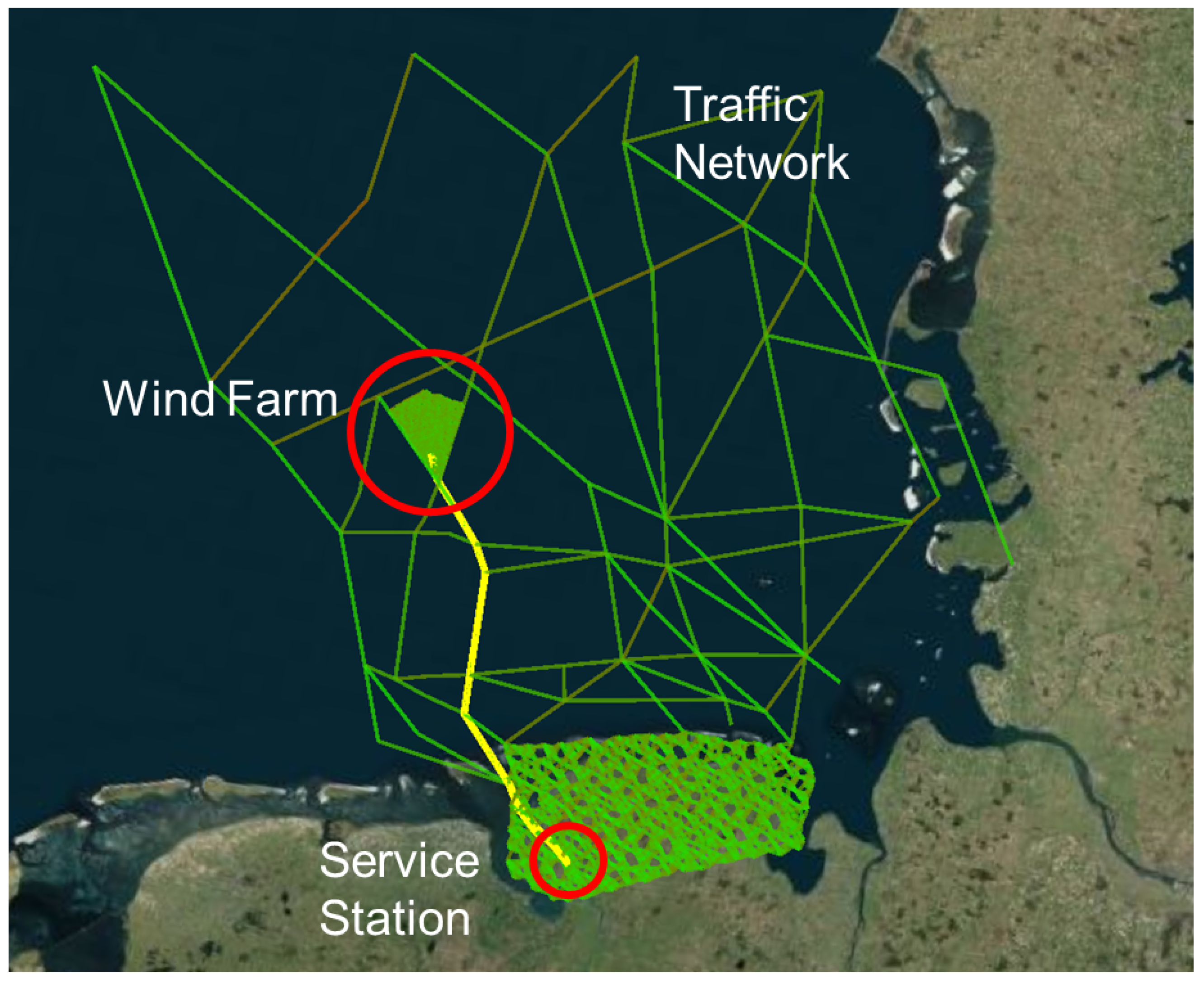
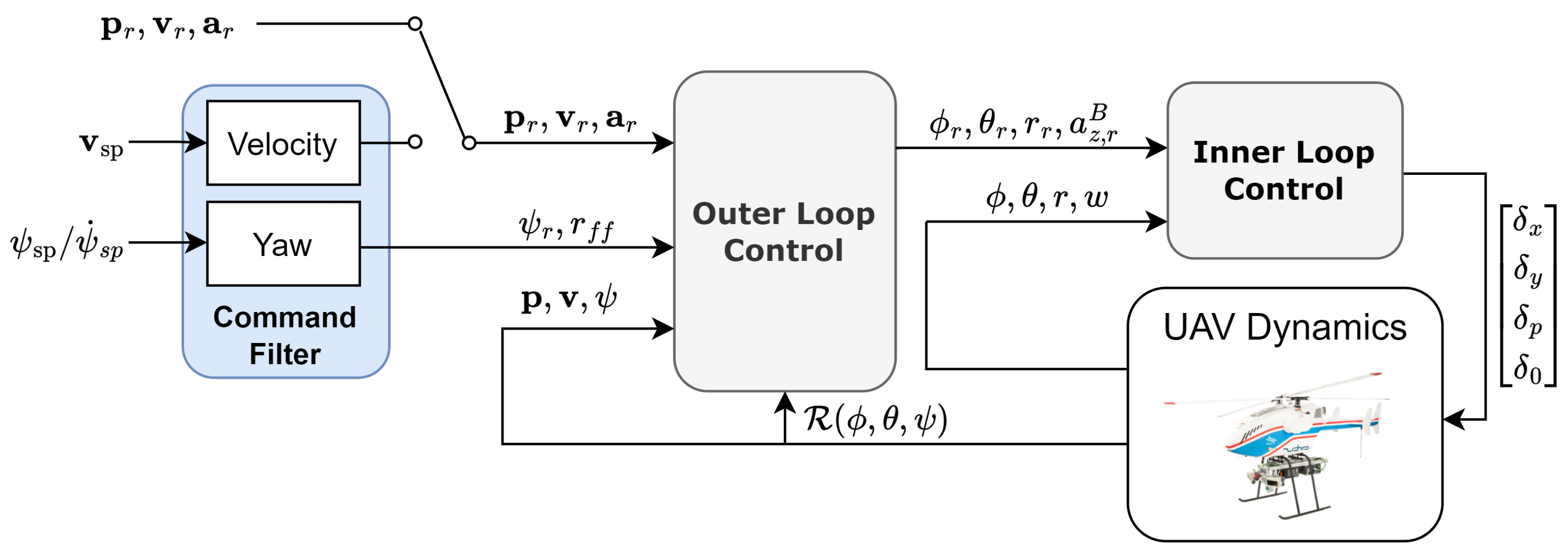
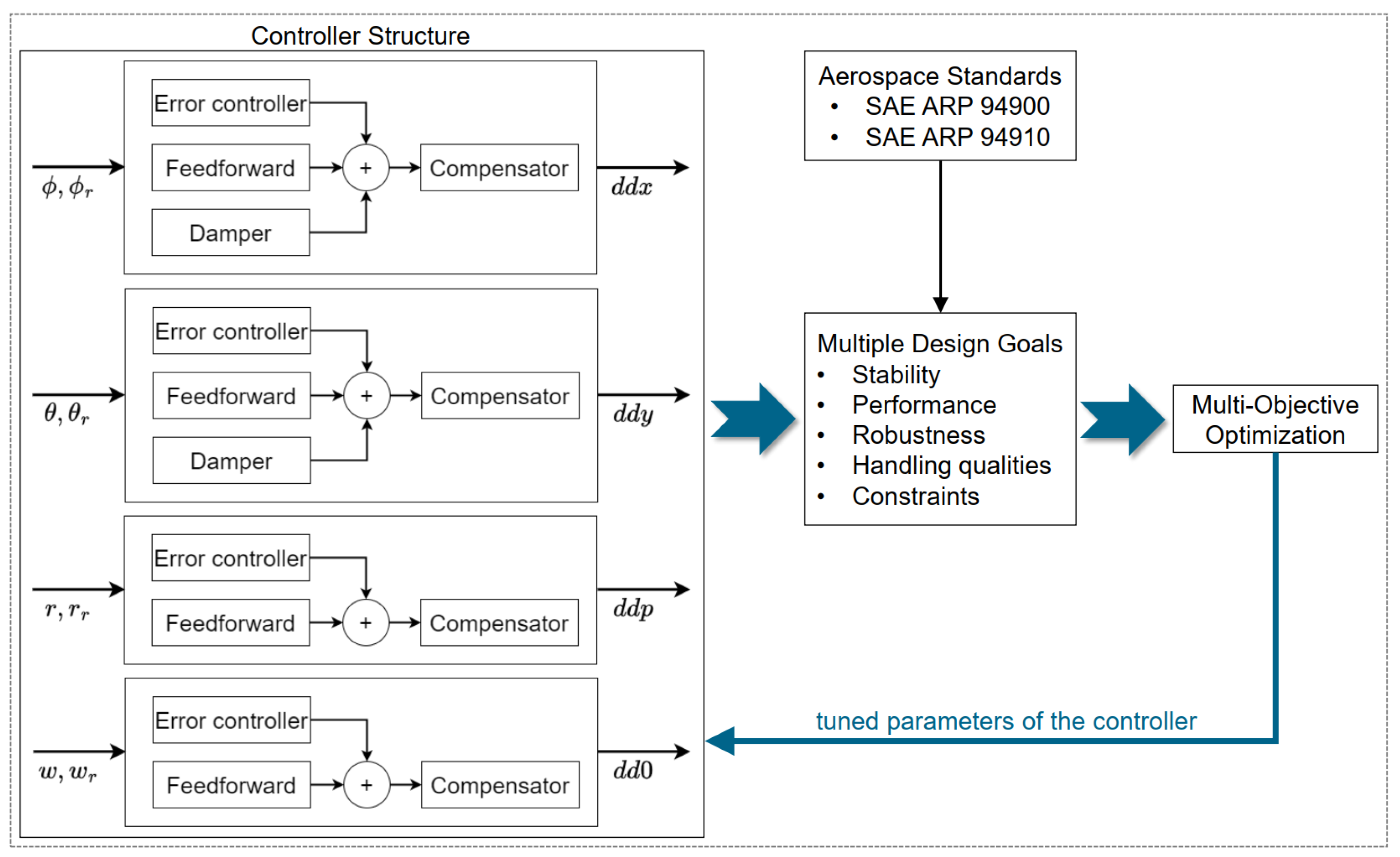

Disclaimer/Publisher’s Note: The statements, opinions and data contained in all publications are solely those of the individual author(s) and contributor(s) and not of MDPI and/or the editor(s). MDPI and/or the editor(s) disclaim responsibility for any injury to people or property resulting from any ideas, methods, instructions or products referred to in the content. |
© 2025 by the authors. Licensee MDPI, Basel, Switzerland. This article is an open access article distributed under the terms and conditions of the Creative Commons Attribution (CC BY) license (https://creativecommons.org/licenses/by/4.0/).