1. Introduction
Today’s automobile industry demands technology for strengthening parts using thin plates to achieve weight reduction. One of the technologies applied to increase the strength of ultra-high-strength steel (AHSS or UHSS) sheet is the hot stamping method. The disadvantages of hot stamping are that post-processing (piercing and trimming) work becomes difficult. Currently, most of the post-processing for hot stamping is carried out by the laser process, which is a contributing factor for low productivity and increasing the production cost. This problem can be solved by replacing the laser process with the shearing process with the press [
1]. To introduce and apply a press process to a hot-stamping process, the punch mold for cutting with high strength (high hardness and high wear resistance) and high toughness is required.
There are several methods of metal 3D printing technology. Metal-based 3D printing systems are divided into a powder bed system (PBS), powder feed system (PFS), and wire feed system (WFS). PBS (Powder Bed System) is a method of using a laser or electron beam as an energy heat source for a powder bed. It is called PBF (Powder Bed Fusion) method. PFS (Powder Feed System) is a method of melting/depositing using a laser while directly supplying powder. It is called the Directed Energy Deposition (DED) method. WFS (Wire Feed System) is a method of using an energy source while supplying a wire rod. This is a method similar to welding, and a lot of research has been done recently [
2,
3,
4,
5].
In recent years, as the interest in the application of 3D printing technology to the mold field has increased, many studies on additive manufacturing using mold steel powder have been conducted [
6,
7,
8,
9]. The piercing punch manufacturing using a powder bed fusion (PBF) method of metal 3D printing and a mold steel powder (H13, D2, M300, KP4) has been attempted [
10]. In this study, punch fabrication and durability tests were conducted on low carbon mold steel powder (M300, KP4). However, in the case of high carbon materials (H13, D2), verification was not possible due to the limited characteristics of additive manufacturing. On the other hand, to overcome the limitation on the lamination of high-strength tool steel powder, many studies have been conducted on mold repair and mold strengthening through partial addition of heterogeneous materials using the directed energy deposition (DED) method [
11,
12,
13,
14]. In these studies, to obtain the mechanical properties required for a punch mold, a high toughness material with a relatively low strength was applied to the substrate material, and a high strength functional part was partially additive with a high strength powder. That is, a partial additive method of heterogeneous materials was used to improve the mechanical properties of the punch mold. However, the level of hardness and toughness applicable to the post-processing (piercing and trimming) of hot stamping has not been reached. Thereupon, a study has been attempted on the additive manufacturing of high-speed tool steel powder materials in the field of partial strengthening of the punch molds. Kim et al. [
15] showed that high-speed tool steel AISI M2 powder improved the surface hardness of surface-hardened tools by 30–50% compared to conventional D2 tool steel. Baek et al. [
16] deposited H13 (mold steel) powder and M2 (high-speed tool steel) powder on a D2 (cold press mold material) substrate for the purpose of surface hardening and compared the mechanical properties with D2 (reference material hardened by heat treatment). Although the hardness was improved in this study, toughness should be further improved for punch molds. Lee et al. [
17] deposited high-speed tool steel M4 powder (1.5 mm high) on an AISI 1045 substrate, increasing the preheating temperature from room temperature to 500 °C to test the effect of the preheating process on the additive manufacture of metal powder. This study suggested the necessity of a preheating process for the substrate material to reduce cracks at the interface due to the thermal stress generated in the rapid solidification process of the additive part when additive manufacturing high-speed tool steels use DED method. Shim et al. [
18] pre-heated the AISI D2 substrate using an induction heater, depositing the high-speed tool steel AISI M4 powder by the DED method. In this study, the effects of induction pre-heating on the additive manufacturing properties and mechanical behavior were investigated by observing the deposited specimen of AISI M4 powder. It has been reported that the hardness of the laminated region is improved to about 4.0 times that of the substrate D2. Additionally, the need for annealing heat treatment has been suggested to compensate for the decrease in toughness that appears as the hardness increases.
The punch mold for the cold pressing process of high-strength components requires high toughness, in addition to high hardness and wear resistance. The high-speed tool steel-based powder materials can obtain increased hardness and wear resistance, but they have the disadvantage of low toughness against impact. If there is no preheating process, the high-speed tool steel may have a very limited additive manufacturing range, and the additive manufacturing may not be possible.
In this paper, high wear resistance steel (HWS) powder material with excellent additive manufacturing properties was produced as a specimen without a preheating process. An improved method was proposed for overcoming the low additive characteristic of the tool steel material and the low toughness of the punch mold by using the HWS powder material and the Semi-AM (additive manufacturing) method.
2. Experimental Process
2.1. Additive Manufacturing DED Method and Equipment
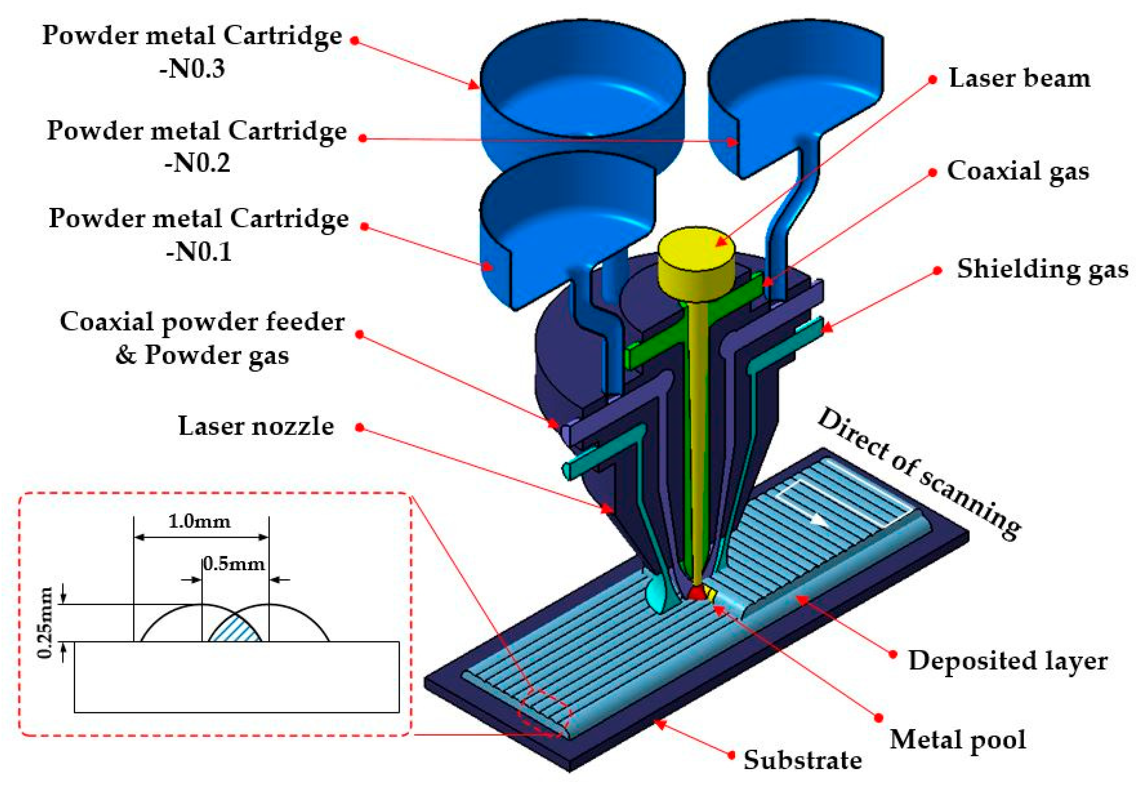
Directed energy deposition (DED) additive manufacturing of metal 3D printing is a method in which metal powder is completely melted using a high-power laser, depositing one layer at a time. This DED method yields excellent products because full fusion is achieved at the interface layer between the additive materials. Moreover, since the additive quality has a dense structure, there is an advantage suitable for mold manufacture. The DED method also has disadvantages in that a laser is expensive, requires a long time to manufacture, and necessitates post-processing because the output surface is rough. Currently, studies are being actively conducted to locally strengthen punch molds using the DED method to improve mold life in the field of forming an ultra-high-strength sheet plate. Furthermore, due to the advantages of dense structure and excellent mechanical properties, applications in the mold industry are increasing, such as mold hard-facing, mold remodeling, and mold repair.
Generally, the additive layer thickness of the DED method is in the range of 100–300. Most of the heat sources use a CO
2 laser beam, and the diameter of the laser beam is about 0.8 to 1.0 mm. The powder material is mainly a spherical powder in the range of 40–140 μm. The shape of the powder material is closer to the spherical shape, and the more uniform the particle composition, the better the fluidity during feeding. The DED equipment in this study used an MX3 metal printer (made by the InssTek in Korea), and the device configuration and additive layer concept are shown in
Figure 1. The equipment consists of a 4 kW CO
2 laser supply system, a five-axis NC machine tool, a powder feeding device consisting of three hoppers, a coaxial powder nozzle, and MX-CAM software. Here, the coaxial powder supply nozzle head forms a uniform molten pool because the powder and the laser are supplied symmetrically. The shielding gas supplied coaxially serves to prevent oxidation of the molten pool.
2.2. Material Characteristics Used in Additive Manufacturing
The HWS used in this study is a high toughness, high wear resistance, cold tool steel material. It has been specially designed for hard cutting of advanced high strength steel (AHSS). The HWS outperforms heat treatment before final machining, like most tool steels and other specialty steels series. The optimum mechanical and physical properties may be obtained through heat treatment [
19].
The substrate material used in this study was AISI (The American Iron and Steel Institute) D2 (SKD11). The D2 material is an alloy tool steel that is widely used in cold press molds and other mold materials due to its excellent wear resistance, toughness, and cutting ability. As a substrate material, a plate having dimensions of 100 L × 60 W × 10 T was used. The surface of the substrate plate was processed to roughness of 50 μm (Rz) and then washed with acetone before the additive manufacturing. The mechanical properties of the HWS (bulk HWS) material, which is the raw material of the metal powder, and SKD11 (Bulk D2), which is the substrate material, are shown and compared in
Table 1 [
20].
The HWS powder is a CPM (Crucible Powder Metallurgy) series powder with high wear resistance, hardness, and toughness, which is a high-carbon alloy tool steel containing alloying elements that form various types of carbides, with the chemical composition shown in
Table 2.
There is no quantified value from the manufacturer for the chemical composition of the HWS powder.
However, the manufacturer (ROVALMA) suggests the composition range through the graph (in the
Supplementary Materials). Therefore, the chemical composition of HWS powder material shown in
Table 2 is the research result data.
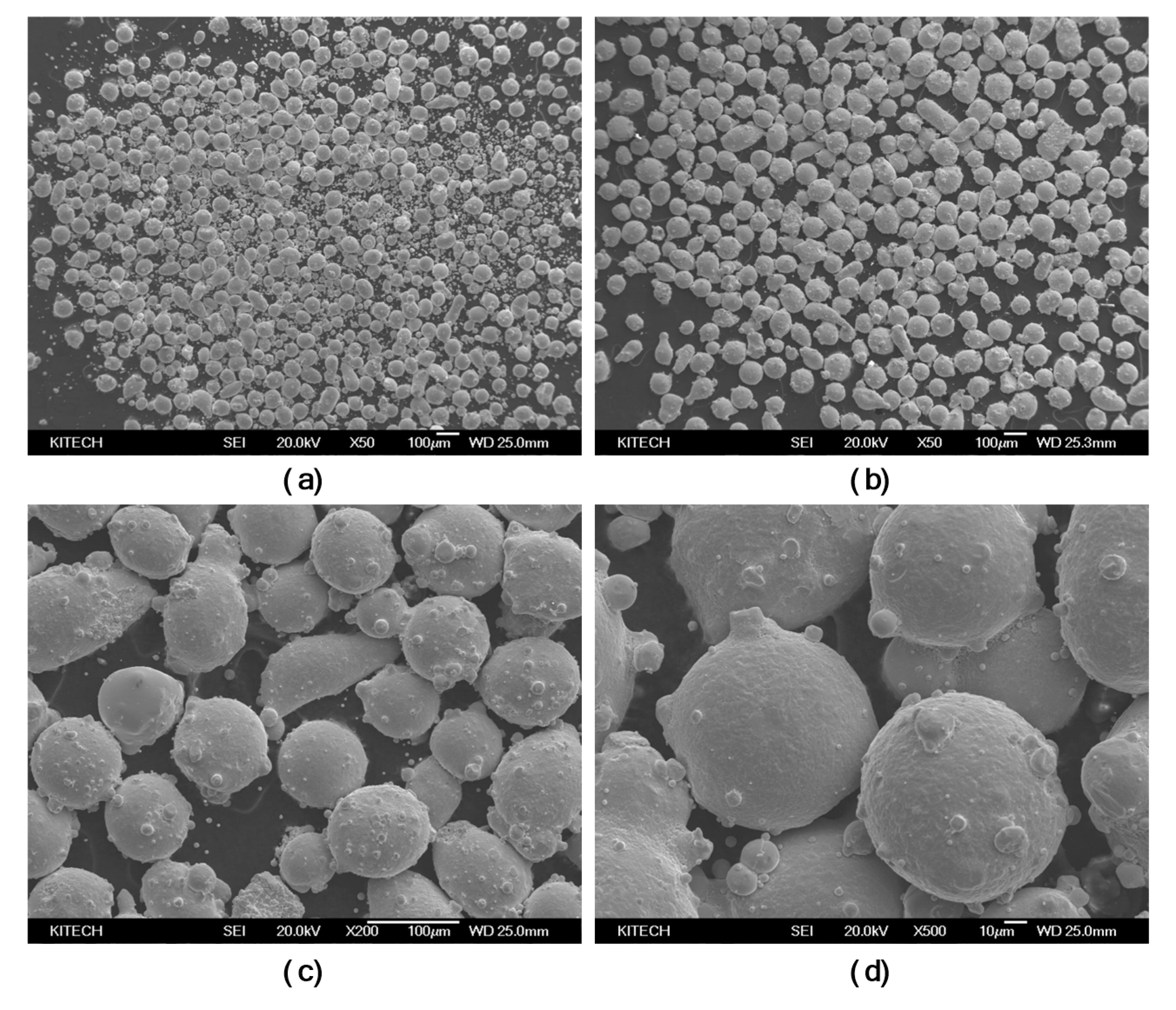
To apply the metal powder material to the AM process of metal 3D printing, the size of the powder particles must be analyzed. The HWS powder was sieved to select particulates with a size suitable for DED application, except for about 20% fine powder. As a result of analyzing 5000 samples through particle analysis, it was confirmed that the shape was close to spherical and favorable for additive manufacturing. However, in the SEM image analysis result in the sample, it was confirmed that several satellite powders were formed on the spherical particles. The quality was somewhat inferior to other high-speed steel powder particles. In the particle size analysis, the particle size distribution, on average, showed a range of 70 to 140 μm, demonstrating that it has a particle size distribution suitable for DED applications. The SEM images of samples before and after sieving the HWS powder are shown in
Figure 2; the images in (a) and (b) show powder states before and after sieving, respectively, and the images in (c) and (d) show that the particle shape is close to a spherical shape. In addition, in
Figure 2c,d, it can be observed that satellite powder particulates are present around the particles.
The particle shape of the satellite powder may impair the fluidity when supplying the powder, which may deteriorate the quality of the additive manufacturing. It has also been reported that proper inclusion of satellite powders affects the melting of the powder, thereby affecting the dense metallic structure of the additive product.
The main process parameters in the DED method include laser power, powder feed rate, track scan interval, and laser scanning speed. Optimization of these process parameters affects the additive characteristics and the quality of the additive product. Here, the process parameters between the substrate material D2 and the heterogeneous material of the powder material (HWS, P21) are shown in
Table 3.
2.3. Specimen Fabrication and Test Methods for Property Evaluation of the AM Material
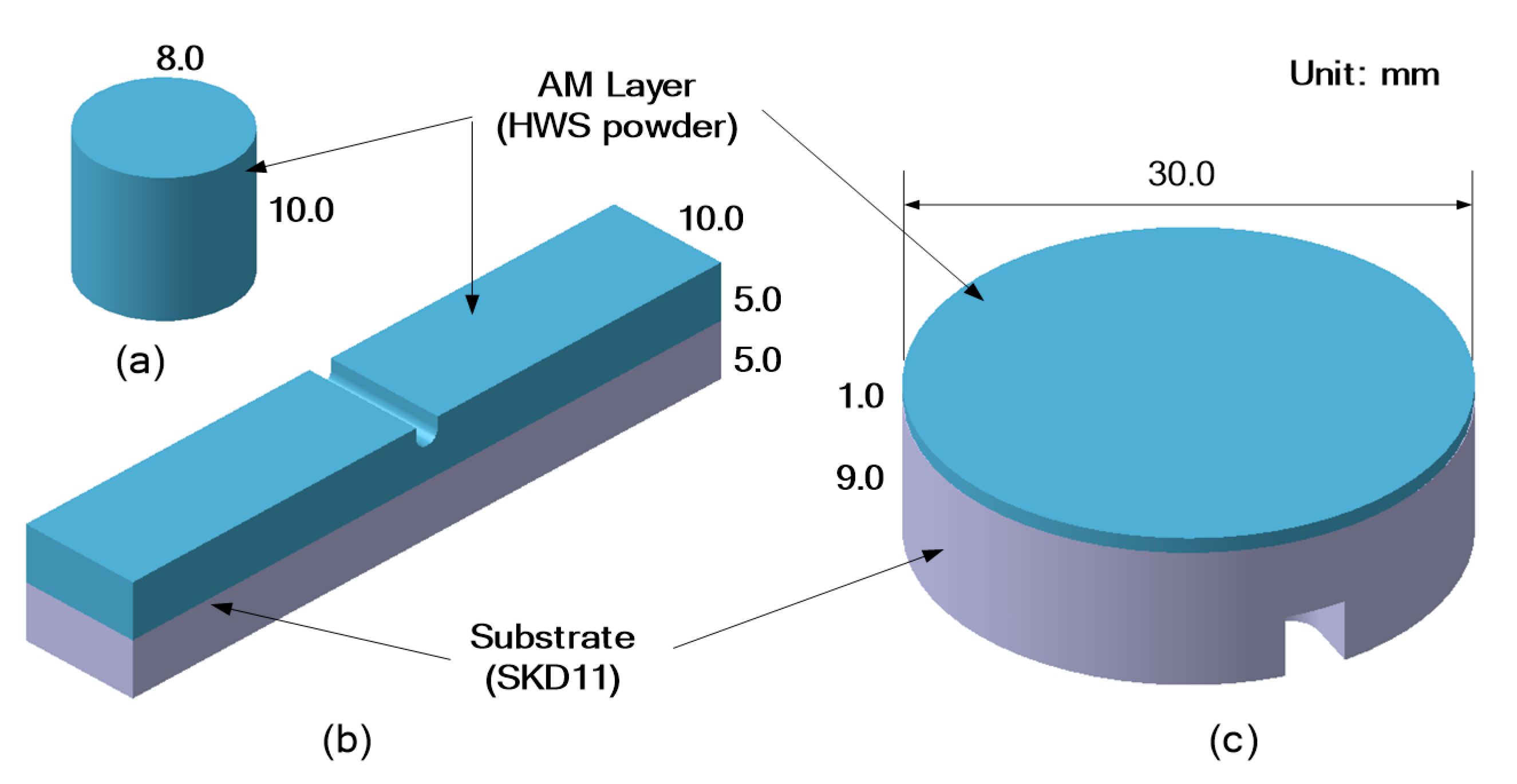
To evaluate the mechanical properties of the AM (Additive Manufacturing) material of the HWS powder produced in this study, the concept of semi-AM specimens was introduced. AM specimens of the HWS powder were designed and fabricated, as shown in
Figure 3 and
Figure 4, to apply a heterogeneous material semi-AM method. Here, the semi-AM refers to a method in which the desired material is deposited in a multi-layer with one or more heterogeneous materials in consideration of the material properties at a predetermined thickness in the desired portion.
Figure 3a shows the design shape of the AM specimen for the compressive strength test and density measurement, and
Figure 3b shows the design shape of the AM specimen for the impact absorption energy measurement.
Figure 3c shows the design shape of the AM specimens for the wear resistance and hardness tests. The base specimens of the heterogeneous materials’ semi-AM were deposited flat while crossing in a line-by-line and zig-zag method (
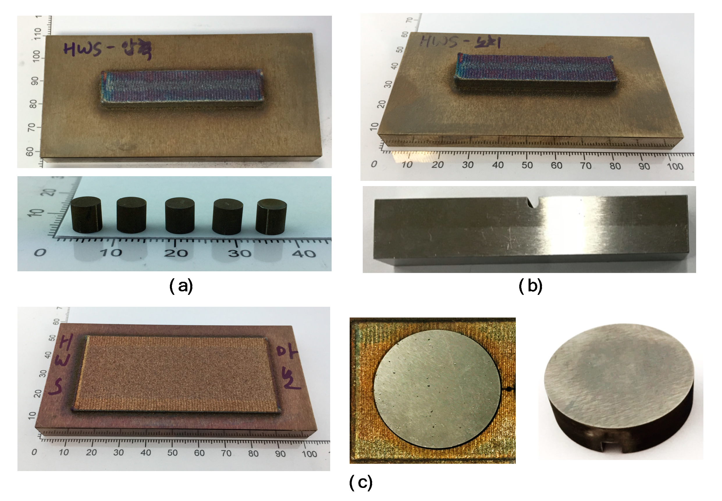
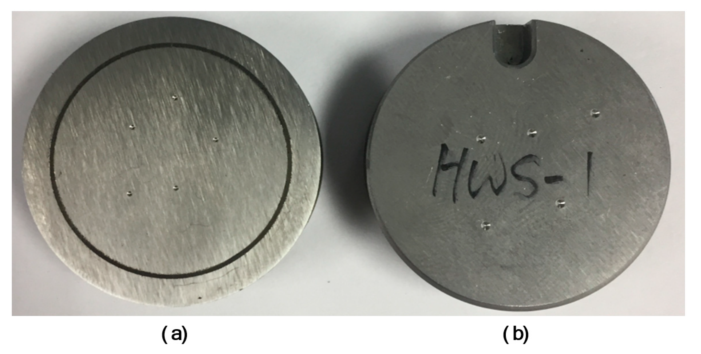
Figure 1). The basic specimens were over-deposited within a range of 1 mm for machining margin, depending on the shape of the specimens. The basic specimen produced by the semi-AM method of the heterogeneous materials is shown in
Figure 4. This base specimen was subjected to a strengthened heat treatment before machining. Here, the basic specimen means a semi-AM material before machining into a specimen in which a powder material is deposited on a substrate material.
Figure 4a shows the basic specimen before machining for the compression test and the finished specimen after machining, respectively. This compression specimen was fabricated by full-additive manufacturing, only the powder material to enable both compression and density measurement tests. In this basic specimen, a powder material having a size of 7 W × 60 L × 7 T was deposited on a D2 substrate material (60 W × 100 L × 10 T).
The compression specimen was completed by separating only the additive portion from the basic specimen and then machined. The specifications of the compression test specimen are based on ASTM (American Society for Testing and Materials) E9-89a. The basic specimen for the impact test specimens and the finished specimen after machining are shown in
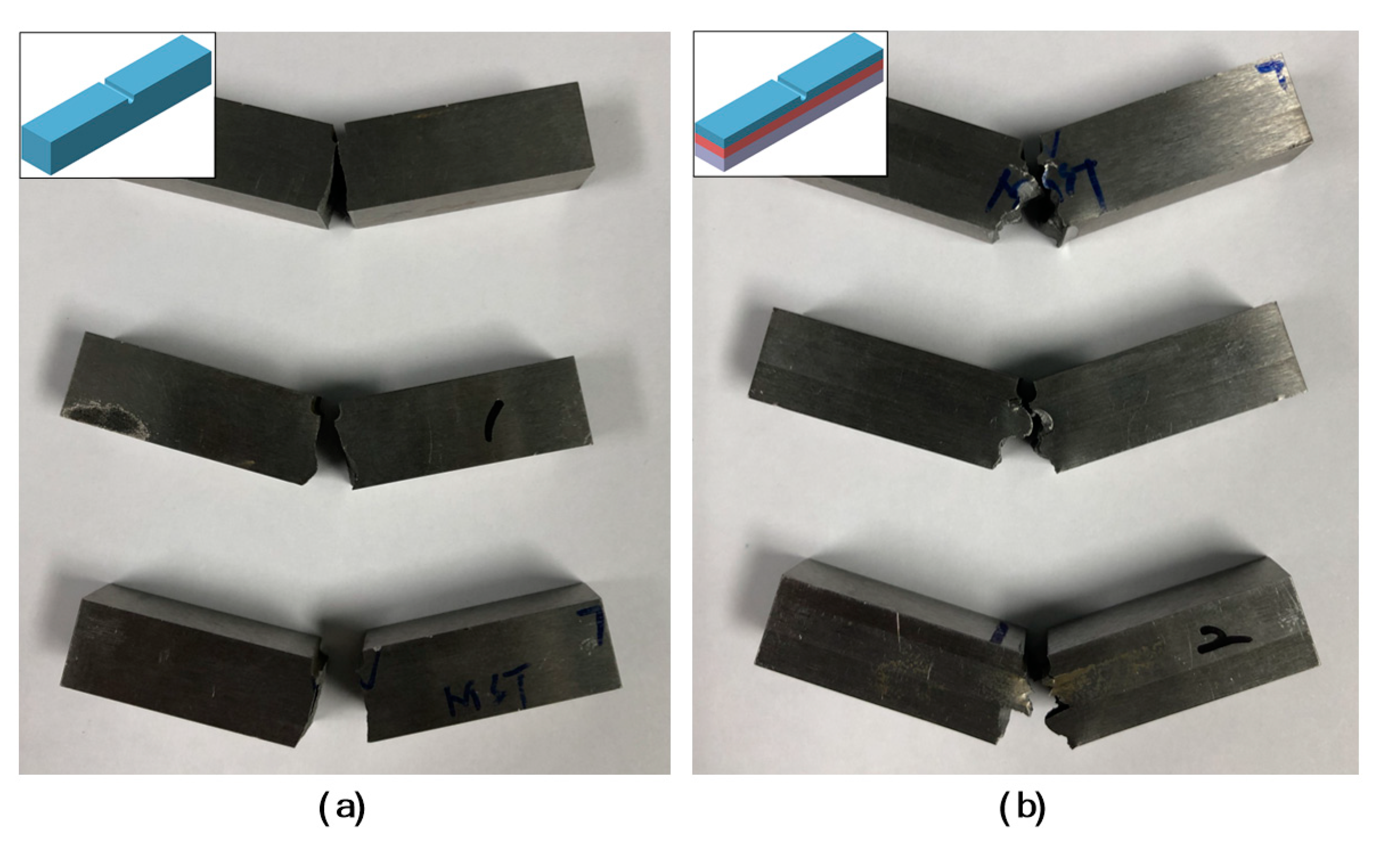
Figure 4b, respectively.
This basic specimen was deposited with powder material of half the thickness of the specimen in order to increase energy absorption. In this case, to further improve the absorption of the impact energy, a specimen may be manufactured through two or more kinds of multiple materials and multi-layer AM. The basic specimens before machining for the impact test had deposited powder materials with a size of 11 W × 60 L × 5.75 T on a D2 substrate material (60 W × 100 L × 10 T). Further, the impact test specimen was machined with a 2-mm-deep U-notch according to the ASTM E23 standard. Particularly, to verify whether the basic specimen for the impact specimen is defective at an interface between heterogeneous materials, only one specimen is deposited independently at the center on one substrate.
For the wear test, the basic specimen before machining and the finished wear specimen after machining are shown in
Figure 4c. The wear specimen was deposited on a 10 mm substrate at a thickness of 1.5 mm, in consideration of the equipment characteristics for the wear resistance test. The basic specimen before machining was deposited with a powder material that had a size of 55 W × 80 L × 1.5 T on a D2 substrate material (60 W × 100 L × 10 T). The wear specimen was machined after cutting it into a cylindrical shape using a wire cutter.
On the other hand, another specimen was also prepared to experimentally compare the physical properties of the semi-AM specimen of the heterogeneous materials. This comparative specimen was prepared using bulk D2 (SKD11) and bulk HWS. All specimens were subjected to heat treatment.
The test method for the mechanical properties of the AM material proposed in this study has not been established yet. Therefore, all mechanical property tests were performed according to the existing KS (Korean Standards) or ASTM standard test method.
The compression tests were performed using an Instron 5582 (Norwood, MA, USA), and the compression test speed was set to 0.5 mm/min.
The impact test was performed at room temperature using Charpy test equipment, and the impact energy, impact velocity, and impact angle were set to 30 J, 3.8 m/s, and 150°, respectively. The basic hammer weight and pendulum radius are 24.1 kgf and 0.25 m. The impact absorption energy was calculated from the set value, and the state of the fracture section was observed.
The wear resistance test was used—Ball-on-Disk Wear Tester equipment (R & B Inc., Daejeon, Korea). The test was forcibly rotated on the top surface of the specimen for 10 min at 147.1 N (15 kgf) load and 10.49 rad/s (100 rpm) ball speed. The wear resistance evaluation of the test specimen measured the weight loss, and the weight loss analyzed the weight change before and after the test.
The hardness test was performed by a depth-sensitive micro indentation test using the HR-521 Rockwell hardness test equipment (Akashi, Japan). The hardness measurement was carried out with a load of 150 kg applied to each indentation point for 15 s. The hardness value at each indentation pointer was analyzed by calculating the area of the compressed scar made on the specimen using the penetrator.
The density measurement analyzed the porosity via X-ray tomography (X-ray micro-tomography). The porosity measurement was carried out using X-ray micro-CT equipment (XT H 225, Nikon, Japan). Here, the lower the porosity, the higher the true density.
3. Test Results and Discussion
The mechanical property test for the AM material of HWS powder was performed to verify that the mechanical properties are enough for a punch mold material. The target value of the mechanical properties for the punch mold material was analyzed by comparing it to bulk D2 (SKD11), which is a common cold mold material. Typically, one of the major mechanical properties in the punch mold for cutting is the hardness of the material, which should be at least 60.0 HRc.
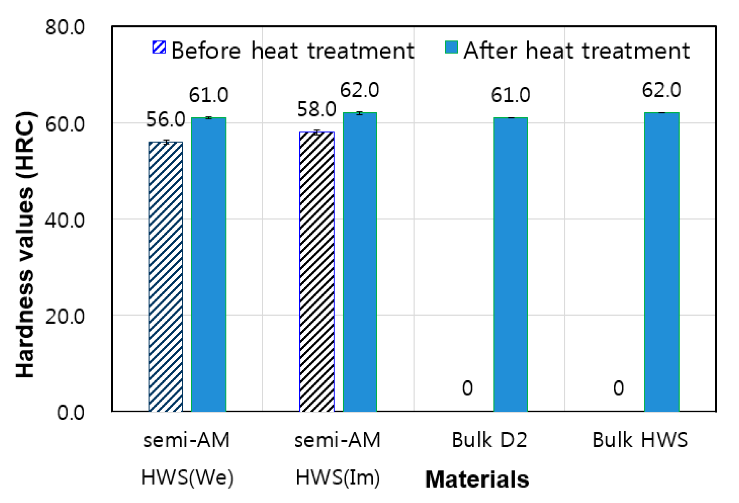
In the hardness test, two types of wear specimens and impact specimens were used. The use of wear specimens can simultaneously measure the mechanical properties of the substrate material of bulk D2 and the AM material of HWS. The impact specimen was used to measure the hardness around the interface between the D2 substrate material and the HWS AM material. The results after the hardness test using wear specimens are shown in
Figure 5 and
Figure 6.
Figure 5a shows the HWS AM material part of the wear specimen, while
Figure 5b shows the D2 substrate material part of the wear specimen. As shown in the graph of
Figure 6, the hardness of the AM HWS (We) material was slightly lower than that of the bulk D2 material. The hardness values before and after heat treatment of the HWS AM materials were 56.0 HRc and 61.0 HRc, respectively, and the heat treatment effect was shown to improve the hardness by about 5.0 HRc. On the other hand, the hardness of the cross-section using the impact test specimen is shown as AM HWS (Im) in
Figure 6. The hardness of the impact specimen was measured at regular intervals from the top to the bottom of the AM HWS (Im) specimen. Here, the hardness values before and after heat treating the AM HWS (Im) specimen were measured to be about 58.0 HRc and about 62.0 HRc, respectively. From the two hardness tests of the wear specimen and the impact specimen, it can be observed that the heat treatment effect improved the hardness of the HWS AM material by about 5 HRc. Additionally, it is noted that the HWS AM material can obtain hardness like the level after heat treatment of the D2 bulk material even by pure additive manufacturing. Additionally, in the impact specimen after heat treatment, the hardness of 62.0 HRc is like the hardness of the HWS bulk material, which satisfies the mechanical properties needed in a punch mold material. However, to make in the punch mold for cutting via the additive manufacture of the HWS powder material, the hardness requires more stabilization. This may be achieved by improving the additive manufacturing process and heat treatment methods.
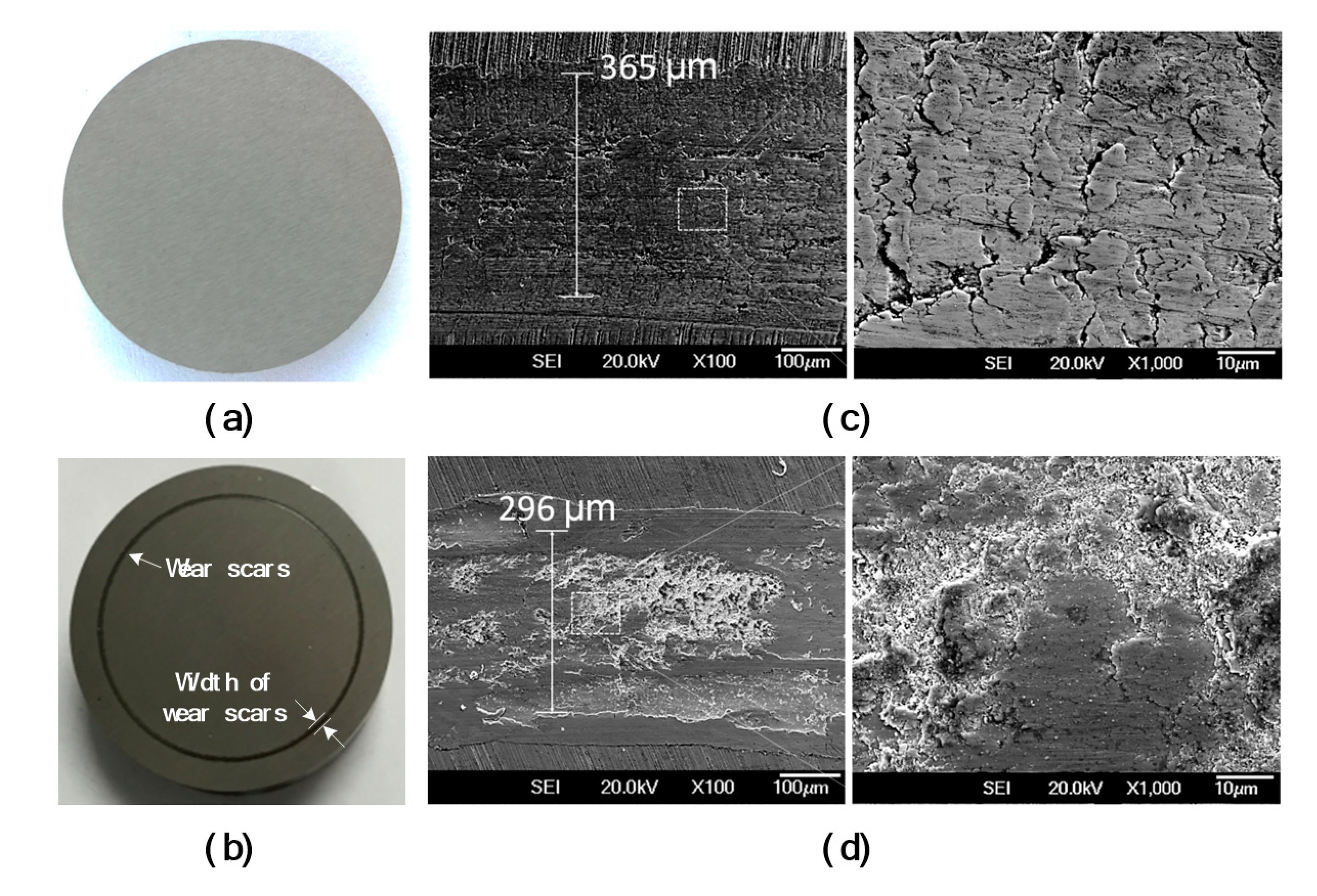
The wear test data were analyzed in two ways by gravimetric and optical measurements. The weight measurement was more difficult due to the small amount of wear compared to the wear track through the three-dimensional volume measurement by the optical method, which gave a more accurate measurement. After wear testing of this semi-AM wear specimen, the state of the specimen is shown in
Figure 7.
In
Figure 7a, the state of the specimen before the abrasion test is shown, and (b) illustrates the state of wear traces upon which a wear track occurred on the surface of the specimen due to the mechanical action between the ball surface and the specimen. The SEM (Scanning Electron Microscope) images of the wear track before and after heat treatment of the HWS AM specimen are shown in
Figure 7c,d. The widths of the wear track traces observed in the SEM images were 365 µm and 296 µm, respectively, before and after the heat treatment. Heat treating the HWS AM material improved the wear resistance by about 23%. The results of the weight measurement and the ballroom measurement for the wear amount of the wear-resistant specimens are shown in
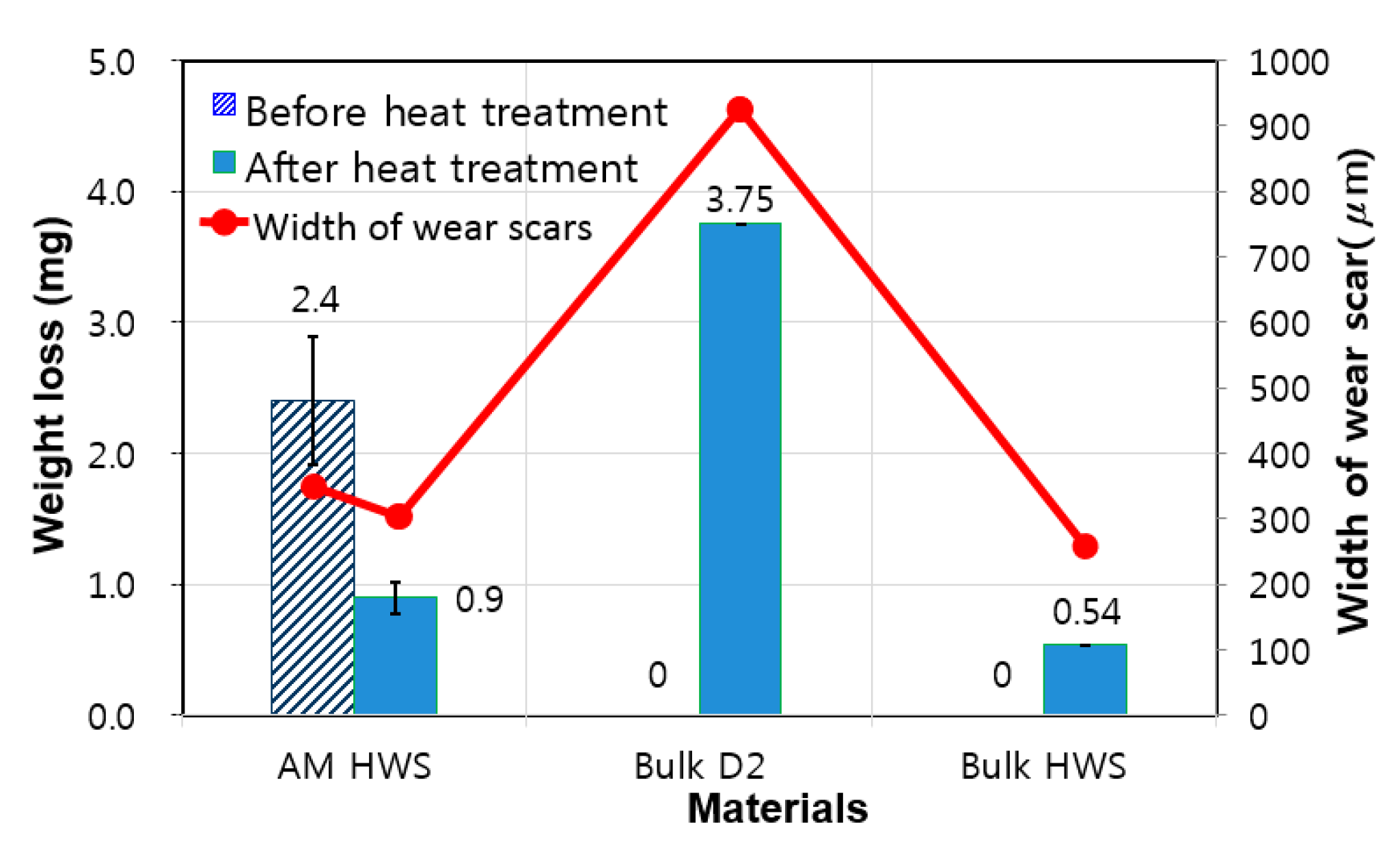
Figure 8.
The gravimetric abrasion resistance of the HWS AM material was shown to be 36.0% and 76.0% higher than the D2 specimen before and after heat treatment, respectively. The improvement effect on the wear resistance caused by heat-treating the HWS AM material was about 40%. The wear resistance based on the volume measurement of the HWS AM material showed values that were 61.0% and 68.5% higher than the bulk D2 specimen before and after heat treatment, respectively. The abrasion weight and volume measurement results were not the same, but they both indicated that the HWS AM material performed significantly better than the bulk D2 specimen. The wear resistance level of the HWS AM material is satisfactory for use as a punch mold material for cutting.
The hardness and wear resistance required for the punch molds are very important, but their toughness against impact is also crucial. This is because the punch mold for cutting used in the pressing process is subjected to repeated large impact loads. There is no specific reference value for the toughness of a punch mold material for cutting, but it should be greater than the toughness of general D2 material. The results of the impact test are shown in
Figure 9 and
Figure 10.
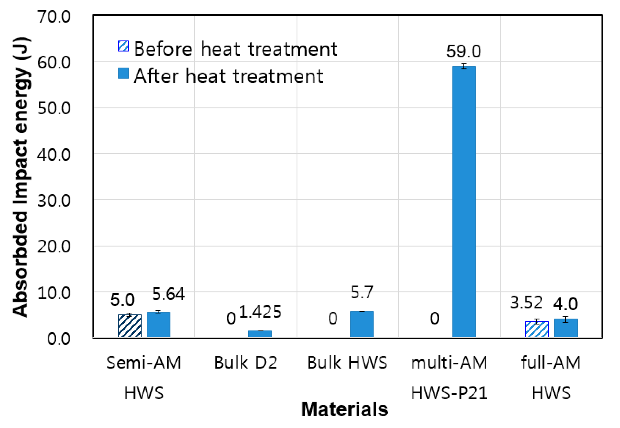
Figure 9a shows an image after the impact test on a full-AM specimen made of pure HWS powder only. As shown in
Figure 10, the impact absorption energies before and after heat treatment of the full-AM specimen of HWS powder were 3.52 J and 4.0 J, respectively. The additive manufacturing material of HWS powder showed a property of improving toughness after heat treatment, unlike ordinary steel materials. The impact absorption energy of HWS semi-AM materials were 5.0 J and 5.64 J before and after heat treatment, respectively. These were about four times higher than that of the bulk D2 specimen (1.425 J). This was like the HWS bulk material 5.7 J, showing that the HWS powder material has excellent additive properties. Especially in the case when a high impact absorption energy was required, it could be improved by using the multiple semi-AM (multi-AM) method with heterogeneous materials, as shown in
Figure 9b. The multi-AM tests with the heterogeneous materials were carried out as follows: first, a P21 powder (buffer layer), which is an impact-resistant material, was deposited on a bulk D2 substrate material as an intermediate buffer layer. HWS powder (strengthening layer) was then deposited on top of the P21-AM material. It was confirmed that toughness was significantly improved. As shown in the graph in
Figure 10, the impact absorption energy of the multi-AM HWS-P21 specimen was 59.0 J, which was seen to be significantly improved compared to other specimens. This means that the mechanical properties of the additive manufacturing material can be customized.
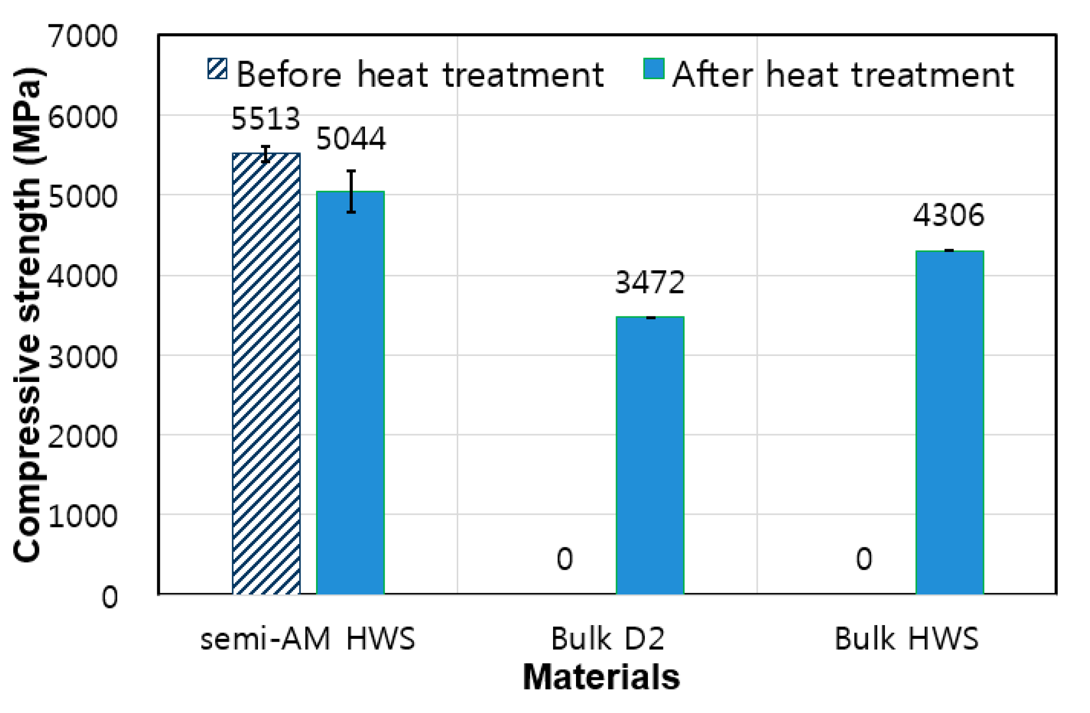
The results of the compressive strength test are shown in
Figure 11.
The compressive strength of the HWS AM specimen after heat treatment was 5044 MPa, which was about 1.45 times larger than that of the D2 bulk material specimen 3472 MPa. This value was 17% higher than that of the HWS bulk material (4306 MPa). In addition, the compressive strengths before and after heat treatment of the HWS AM specimen were 5513 MPa and 5044 MPa, respectively, indicating that the compressive strength before heat treatment was about 9.3% higher. Generally, it is known that the compressive strengths of AM materials are significantly lower than those of solid bulk materials. However, the compressive strength test of this HWS AM specimen showed the opposite result. This is a unique phenomenon, which means that HWS powder material can obtain the mechanical compressive strength levels of bulk material through additive manufacturing. From this, the HWS powder material can be evaluated as a material having excellent additive manufacturing properties.
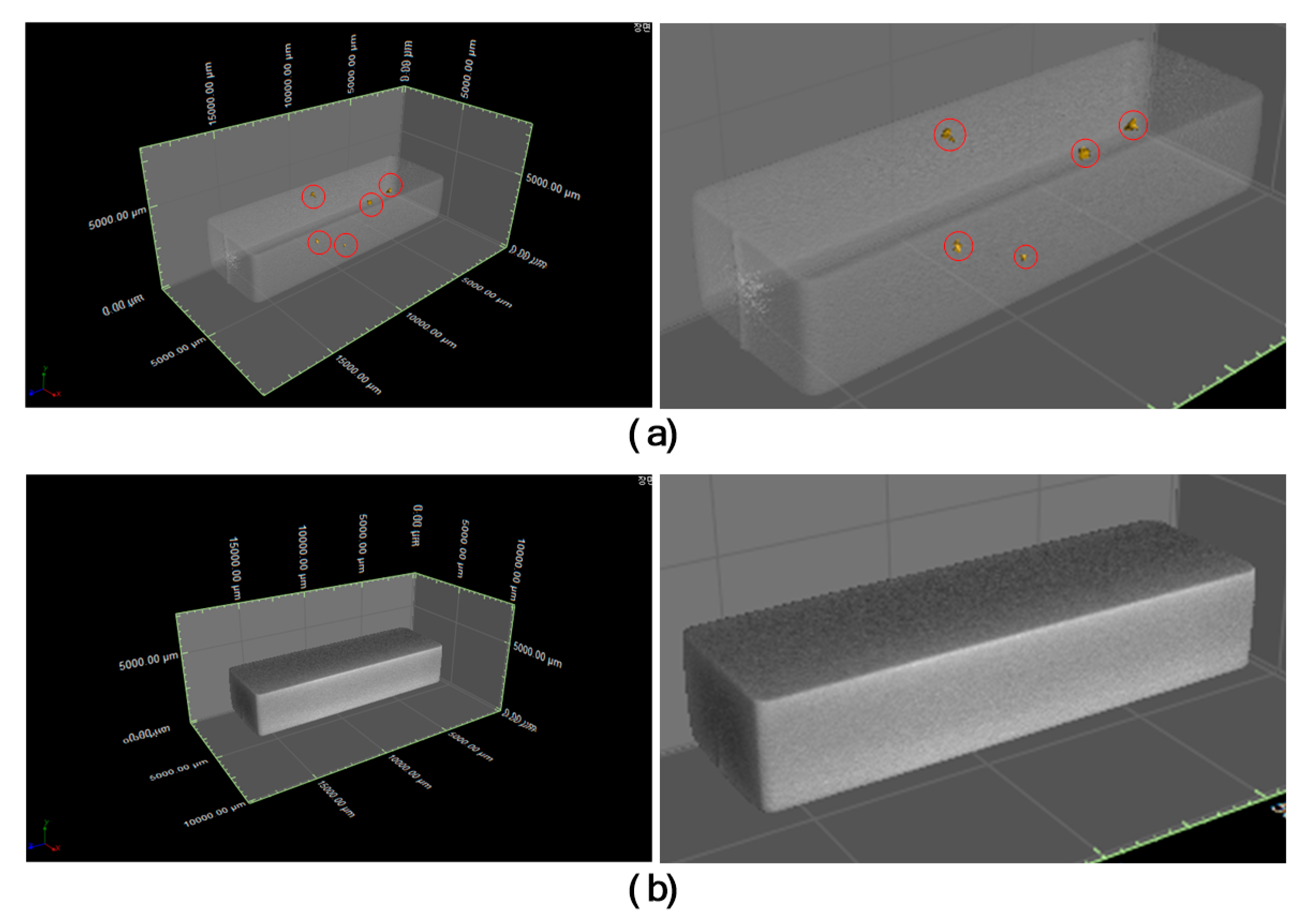
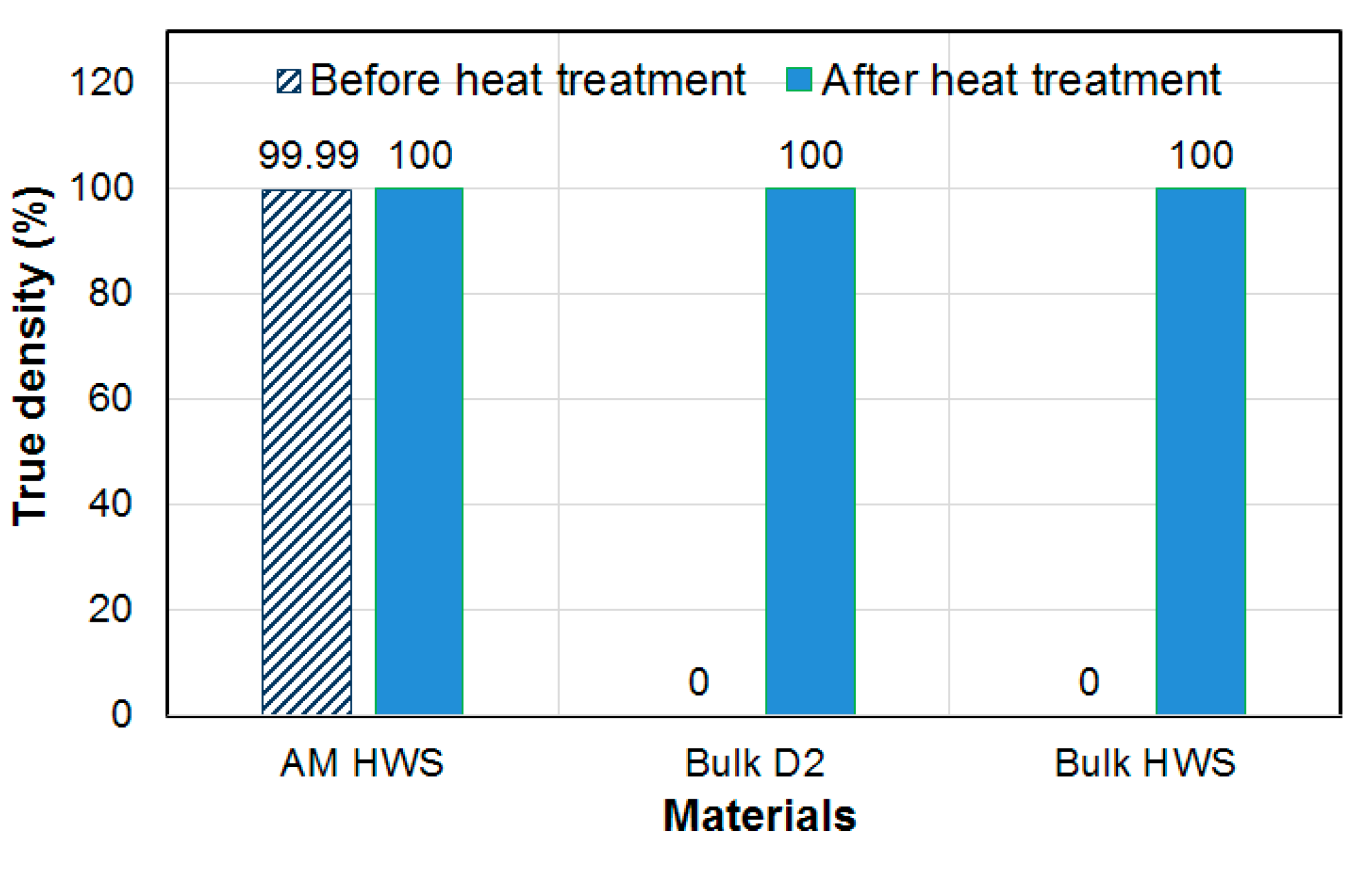
Figure 12 shows X-ray tomography results;
Figure 12a,b show the photographed void state images before and after heat treating the AM specimen of the HWS powder material, respectively. Here, the image before the heat treatment of the HWS AM specimen indicates that there are five void defects, while the image after the heat treatment indicates that there are no void defects. The evaluation of true density is calculated as the ratio of the volume of the measured specimen and the volume of the specimen minus the total void volume. The true densities of the three materials evaluated by X-ray tomography are shown in
Figure 13. The HWS AM specimen showed 0.01% porosity before heat treatment, and the true density was measured to be 99.99%. The HWS AM specimen after heat treatment showed a porosity of 0% and a true density of 100.0%. The true density of bulk material specimens for D2 and HWS was also measured at 100%.
For the AM material to have a dense structure, there should be no pores inside the material. Pores can be formed via several mechanisms, such as lack of fusion, gas entrapment, etc. Some of the pores formed can result in mechanical properties variation. The pores formed in this way directly affect the mechanical properties. Even if the mechanical properties look good externally, there is always a cause for crack defects to occur if the tissue is not internally dense. In this density test, the true density of the HWS AM material showed the same level as that of the bulk material, and it was evaluated as a material showing excellent properties in the additive manufacturing. Although the mechanical properties and physical characteristics look excellent as in this study, unobserved pores may exist in the additive manufacturing material. This is currently the biggest problem to be solved in the practical use of additive manufacturing materials using tool steel powder materials. Therefore, an in-depth study on the observation of microstructure is required for practical use of the additive manufacturing materials [
21,
22].
According to the previous research, the alloy tool steel powder material can obtain high hardness and wear resistance by applying the additive manufacturing technique, but on the contrary, there is a disadvantage in that toughness against impact is weakened. In general, the hardness and strength of tool steels have a corresponding relationship with one another; the higher the hardness, the higher the strength. Furthermore, the higher the hardness, the higher the wear resistance. However, high hardness and strength also typically result in low toughness. In particular, the low toughness in the punch mold for cutting causes a low resistance property to be breaking or cracking of the mold when a sudden impact or load is repeatedly applied.
In this study, to improve the toughness that appears as a weakness in general high-hardness and high-abrasion tool steels, the additive manufacturing specimen was fabricated by applying a semi-AM method of the heterogeneous material and verified through mechanical property tests. It was confirmed that the mechanical properties of the additive manufacturing material of the HWS powder material reached a level that surpassed the D2 material, which is a commonly used cold tool steel material. In the fabricating process of the additive manufacturing specimens using HWS powder materials, the superiority of the additive manufacturing characteristic compared to other tool steel powders was also verified. The introduced HWS powder material and the proposed semi-AM method in this study is thought to be applicable to strengthening the punch mold for cutting.


